US1852593A - Valve for rock drills - Google Patents
Valve for rock drills Download PDFInfo
- Publication number
- US1852593A US1852593A US494850A US49485030A US1852593A US 1852593 A US1852593 A US 1852593A US 494850 A US494850 A US 494850A US 49485030 A US49485030 A US 49485030A US 1852593 A US1852593 A US 1852593A
- Authority
- US
- United States
- Prior art keywords
- valve
- piston
- pressure fluid
- chamber
- pressure
- Prior art date
- Legal status (The legal status is an assumption and is not a legal conclusion. Google has not performed a legal analysis and makes no representation as to the accuracy of the status listed.)
- Expired - Lifetime
Links
Images
Classifications
-
- B—PERFORMING OPERATIONS; TRANSPORTING
- B25—HAND TOOLS; PORTABLE POWER-DRIVEN TOOLS; MANIPULATORS
- B25D—PERCUSSIVE TOOLS
- B25D9/00—Portable percussive tools with fluid-pressure drive, i.e. driven directly by fluids, e.g. having several percussive tool bits operated simultaneously
- B25D9/14—Control devices for the reciprocating piston
- B25D9/16—Valve arrangements therefor
- B25D9/20—Valve arrangements therefor involving a tubular-type slide valve
-
- B—PERFORMING OPERATIONS; TRANSPORTING
- B25—HAND TOOLS; PORTABLE POWER-DRIVEN TOOLS; MANIPULATORS
- B25D—PERCUSSIVE TOOLS
- B25D2209/00—Details of portable percussive tools with fluid-pressure drive, i.e. driven directly by fluids, e.g. having several percussive tool bits operated simultaneously
- B25D2209/005—Details of portable percussive tools with fluid-pressure drive, i.e. driven directly by fluids, e.g. having several percussive tool bits operated simultaneously having a tubular-slide valve, which is coaxial with the piston
Definitions
- This invention relates to rock drills, but more particularly to a valve for fluid actuated rock drills of the hammer type.
- One object of the invention is to obtain a rapid and elflcient distribution of the pressure fluid to the cylinder and consequently a rapid action of the hammer piston of the drill. 7
- Another object is to suitably apportion the flow of pressure fluid to the ends of the cylinder so that a greater charge may be admitted to one end of the cylinder than to the other end within a given period of time.
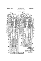
- Figure 1 is a sectional elevation of a rock drill constructed in accordance with the practice of the invention and showing the valve and the piston in certain limiting positions, and
- Figure 2 is a view similar to Figure 1 showing the valve and the piston in other limiting 5 posltions.
- A designates generally a rock drill comprising a cylinder B having a piston chamber C to accommodate a reclprocatory hammer piston D.
- a closure is provided for the front end of the piston chamber C in the form of a bushing E which is suitably bored to act as a guide for a stem F of the piston D and whereby the blows of the piston are delivered to a working implement, only the shank G of which is shown.
- the bushing E may, as shown, also serve to centralize a front head H with respect q to the cylinder B.
- suitable chuck mechanism designated generally by J to serve as a guide for the working implement and also to transmit rotary movement of the piston D to the working implement, it being understood that the extension or stem F of the piston is slidably interlocked with the chuck mechanism in a well known manner.
- a port R' which is adapted to register with a passage S in the back head 0 and which passage opens into a supply reservoir T in the form of an annular groove in the inner or front end of the back head 0.
- the back head 0 may be secured in the proper assembled position in any suitable manner, as for instance, by the usual side bolts (not shown) and which side bolts may also serve as a means for clamping the front head H to the cylinder.
- valve chest Disposed within the bore K adjacent the rear end of the piston chamber C for which it forms a closure is a valve chest comprising in this instance a block U arranged adjacent the rear end of the piston chamber C and a plate V seated upon the rear end of the block.
- the plate V in turnacts as a seat for a ratchet ring W which is interposed between the plate V and the back head 0.
- the ratchet ring IV is shown provided with the usual introverted teeth X to act as abut ments for pawls Y carried by the head Z of a fluted rifle bar Z) wherewith the piston D is slidably interlocked.
- the rifle bar 6 thus extends through the valve chest, and in the present instance a bushing c is disposed in the block U and the plate V to act as a renewable bearing surface for that portion of the rifle bar I) which lies within the confines of'the valve chest and also to prevent the leakage of pressure fluid along the rifle bar into the piston chamber. 7
- valve chest The parts comprising the valve chest are bored to form a valve chamber cl for the accommodation of a distributing valve 6 shown in this instance as being of the reciprocatory type and having a central bore f through which the bushing 0 extends.
- the valve 6 is provided with an intermediate flange g which controls the outlet opening or port h of a supply passage j leading from the supply reservoir T to the valve chamber (Z.
- the head 9 in this instance is of smaller diameter than the head is and therefore of smaller diameter than the flange g.
- the pressure fluid utilized for actuating the valve 6 is conveyed from the piston chamber C to the pressure chambers 29 and 8.
- the cylinder is provided with kicker passages t and u.
- the kicker passage 25 opens with one end into the cylinder at a point for wardly of the transverse median line of the piston chamber G and communicates with its opposite end with the pressure chamber 10.
- the kicker passage u leads from the piston chamber C at a point rearwardly of the transverse median line of said piston chamber and opens with its opposite end into the pressure chamber 8.
- the kicker passages t and u are provided with atmospheric vents o and w respectively of smaller cross sectional area than the kicker ports. lVith the kicker passages and the vents thus proportioned a full supply of pressure fluid may be introduced into the pressure chambers 79 and s for actuating the valve 6 from one limiting position to the other and at the same time an immediate outlet is provided for the pressure fluid in the pressure chambers p and s after the valve is thrown.
- the pressure fluid utilized for actuating the piston D is conveyed into the rear end of the piston chamber C by a rear inlet passage m which is preferably located in the block U and opens into the valve chamber (Z at a point immediately forwardly of the outlet opening h of the supply passage j, and pressure fluid is conveyed to the front end of the piston chamber C by a front inlet passage g which opens into the valve chamber d at a point immediately rearwardly of the port 72.
- the inlet passages 02 and y also serve as exhaust passages for conveying exhaust fluid from the piston chamber to the valve chamber and in the valve chest and in the portion of the cylinder adjacent thereto is an exhaust port B through which exhaust fluid may pass to the atmosphere.
- the charges of pressure fluid to the ends of the piston chamber C may be suitably apportioned so that a greater charge will be delivered to the rear end of the piston chamber for driving the piston D on its working stroke than will be admitted to the front end of the piston chamber for lifting or retracting the piston D
- the flange g is provided on its front and rear ends with annular recesses z and 2 respectively, thus leaving an intermediate raised or stepped portion 3 in slidable engagement with the wall of the valve chamber (Z.
- the annular recess a which controls the flow of pressure fluid from the supply passage y' to the inlet passage 00 is of greater depth than the annular recess 2.
- the rear and front ends of the flange g or more particularly, those areas of these portions of the flange g which are in excess of the diameters of the heads and g, constitute holding surfaces 4 and 5 respectively against which pressure fluid flowing from the supply passage to the inlet passage acts to hold the valve 6 in its limiting positions.
- the pressure fluid previously admitted into the pressure chamber 10 will then immediate 1y escape through the kicker passage and the atmospheric vent Q) so that at a proper period in the cycle of operations the valve 6 may again be thrown forwardly and which movement will only be opposed by the pressure acting against the front holding surface 5.
- a valve chest having a valve chamber and a supply passage, inlet passages leading from the valve chamber to the cylinder, a valve in the valve chamber having a flange to control the flow of pressure fluid from the supply passage to the inlet passages, opposed pressure surfaces on the valve against which pressure fluid acts for throwing the valve, holding areas on the valve intermittently exposed to pressure fluid for holding the valve in the limiting positions, and means on the flange cooperating with the valve chest to assure a greater area of communication between the supply passage and one inlet passage than between the supply passage and the other inlet passage.
- a valve chest having a valve chamber and a supply passage, inlet passages leading from the valve chamber to the cylinder, a valve in the valve chamber having a flange to control the flow of pressure fluid from the supply passage to the inlet passages, opposed pressure surfaces on the valve against which pressure fluid acts for throwing thev valve, holding areas on the valve intermittently exposed to pressure fluid for holding the valve'in the limiting positions, and recesses on the flange through which pressure fluid flows and being of diflerent areas to assure a greater flow of pressure fluid from the supply passage to one inlet passage than to the other inlet passage.
- a valve chest having a valve chamber and a supply passage, inlet passages leading from the valve chamber to the cylinder, a valve in the valve chamber having a flange to control the flow of pressure fluid from the supply passage to the inlet passages, opposed differential pressure surfaces on the valve against which pressurefluid acts for throwing the valve, holding areas on the valve intermittently exposed to pressure fluid for holding the valve in the limiting positions, and control means 011 the "alve for effecting a greater flow of pressure fluid from the supply passage to one inlet passage than to the other inlet passage.
- a valve chest having a valve chamber and a supply passage, inlet passages leading from the valve chamber to the cylinder, a valve in the valve chamber having a flange to control the flow of pressure fluid from the supply passage to the inlet passages, control means on the flange for effecting a greater flow of pressure fluid from the supply passage to one inlet passage than to the other inlet passage, actuating surfaces on the valve intermittently exposed to pressure fluid valved by the piston for throwing the valve, and holding areas on the flange exposed to pressure fluid flowing to the in let passage for holding the valve in the limiting positions.
- a valve chest having a valve chamber and a supply passage, inlet passages leading from the valve chamber to the cylinder, a valve in the valve chamber having a flange to control the flow of pressure fluid from the supply passage to the inlet passages, control means on the flange for effecting a greater flow of pressure fluid from the supply passage to one inlet passage than to the other inlet passage, heads on the valve of smaller diameter than the flange and having differential pressure surfaces intermittently exposed to pressure fluid valved by the piston for throwing the valve, and holding areas on the flange exposed intermittently to pressure fluid for holding the valve in the limiting positions.
- a valve chest having a valve chamber and a supply passage, pressure chambers in the ends of the valve chamber, inlet passages leading from the valve chamber to the cylinder, a valve in the valve chamber having an intermediate flange to control the flow of pressure fluid from the supply passage to the inlet passages, means on the valve to effect differential areas of communication between the supply passage and the inlet passages, heads on the valve of smaller diameter than the flange and having differential pressure surfaces in the pressure chambers, piston controlled kicker passages for conveying pressure fluid from the cylinder to the pressure chambers to actuate the valve, holding areas on the flange intermittently exposed to pressure fluid for holding the valve in the limiting positions, and vents leading from the kicker passages to the atmosphere to exhaust pressure fluid from the pressure chambers.
Description
April 5, 1932. w SMITH, R 1,852,593
- VALVE FOR ROCK DRILLs Filed Nov. 11, 1930 wan;-
Fl -:1 H175 A TTORNE).
via
Patented Apr. 5, 1932 UNITED STATES PATENT OFFICE WILLIAM A. SMITH, 33., E EASTON, PENNSYLVANIA, ASSIGNOR TO IN GERSOLL-RAND COMPANXZOF JERSEY CITY, NEW JERSEY, A CORPORATION OF NEW JERSEY VALVE FOR ROCK DCRILLS Application filed November 11, 1930. Serial No. 494,850.
This invention relates to rock drills, but more particularly to a valve for fluid actuated rock drills of the hammer type.
"One object of the invention is to obtain a rapid and elflcient distribution of the pressure fluid to the cylinder and consequently a rapid action of the hammer piston of the drill. 7
Another object is to suitably apportion the flow of pressure fluid to the ends of the cylinder so that a greater charge may be admitted to one end of the cylinder than to the other end within a given period of time.
Other objects will be in part obvious and in part pointed out hereinafter.
In the drawings accompanying this specification and in which similar reference characters refer to similar parts,
Figure 1 is a sectional elevation of a rock drill constructed in accordance with the practice of the invention and showing the valve and the piston in certain limiting positions, and
Figure 2 is a view similar to Figure 1 showing the valve and the piston in other limiting 5 posltions.
Referring more particularly to the drawings, A designates generally a rock drill comprising a cylinder B having a piston chamber C to accommodate a reclprocatory hammer piston D. a
A closure is provided for the front end of the piston chamber C in the form of a bushing E which is suitably bored to act as a guide for a stem F of the piston D and whereby the blows of the piston are delivered to a working implement, only the shank G of which is shown. The bushing E may, as shown, also serve to centralize a front head H with respect q to the cylinder B.
In the front head is arranged suitable chuck mechanism designated generally by J to serve as a guide for the working implement and also to transmit rotary movement of the piston D to the working implement, it being understood that the extension or stem F of the piston is slidably interlocked with the chuck mechanism in a well known manner.
In the rear end of the cylinder B is an enlarged bore K and into the rearward end of the bore extends a flange L of aback head 0.
In the wall of the throttle valve is a port R' which is adapted to register with a passage S in the back head 0 and which passage opens into a supply reservoir T in the form of an annular groove in the inner or front end of the back head 0.
The back head 0 may be secured in the proper assembled position in any suitable manner, as for instance, by the usual side bolts (not shown) and which side bolts may also serve as a means for clamping the front head H to the cylinder.
Disposed within the bore K adjacent the rear end of the piston chamber C for which it forms a closure is a valve chest comprising in this instance a block U arranged adjacent the rear end of the piston chamber C and a plate V seated upon the rear end of the block. The plate V in turnacts as a seat for a ratchet ring W which is interposed between the plate V and the back head 0. j
The ratchet ring IV is shown provided with the usual introverted teeth X to act as abut ments for pawls Y carried by the head Z of a fluted rifle bar Z) wherewith the piston D is slidably interlocked. The rifle bar 6 thus extends through the valve chest, and in the present instance a bushing c is disposed in the block U and the plate V to act as a renewable bearing surface for that portion of the rifle bar I) which lies within the confines of'the valve chest and also to prevent the leakage of pressure fluid along the rifle bar into the piston chamber. 7
The parts comprising the valve chest are bored to form a valve chamber cl for the accommodation of a distributing valve 6 shown in this instance as being of the reciprocatory type and having a central bore f through which the bushing 0 extends. The valve 6 is provided with an intermediate flange g which controls the outlet opening or port h of a supply passage j leading from the supply reservoir T to the valve chamber (Z.
On the front end of the valve 6 is a head 7c of somewhat smaller diameter than the flange g and the forward end or surface 0 of which constitutes a pressure surface which lies within a pressure chamber p in the front end of the valve chamber (Z. Similarly, on the rear end of the valve 6 is a head 9 the rear end 7 of which lies within a pressure chamber s and constitutes a pressure surface against which pressure fluid may act for actuating the valve. The head 9 in this instance is of smaller diameter than the head is and therefore of smaller diameter than the flange g.
The pressure fluid utilized for actuating the valve 6 is conveyed from the piston chamber C to the pressure chambers 29 and 8. To this end the cylinder is provided with kicker passages t and u. The kicker passage 25 opens with one end into the cylinder at a point for wardly of the transverse median line of the piston chamber G and communicates with its opposite end with the pressure chamber 10. The kicker passage u leads from the piston chamber C at a point rearwardly of the transverse median line of said piston chamber and opens with its opposite end into the pressure chamber 8.
The kicker passages t and u are provided with atmospheric vents o and w respectively of smaller cross sectional area than the kicker ports. lVith the kicker passages and the vents thus proportioned a full supply of pressure fluid may be introduced into the pressure chambers 79 and s for actuating the valve 6 from one limiting position to the other and at the same time an immediate outlet is provided for the pressure fluid in the pressure chambers p and s after the valve is thrown.
The pressure fluid utilized for actuating the piston D is conveyed into the rear end of the piston chamber C by a rear inlet passage m which is preferably located in the block U and opens into the valve chamber (Z at a point immediately forwardly of the outlet opening h of the supply passage j, and pressure fluid is conveyed to the front end of the piston chamber C by a front inlet passage g which opens into the valve chamber d at a point immediately rearwardly of the port 72.. The inlet passages 02 and y also serve as exhaust passages for conveying exhaust fluid from the piston chamber to the valve chamber and in the valve chest and in the portion of the cylinder adjacent thereto is an exhaust port B through which exhaust fluid may pass to the atmosphere.
To the end that the charges of pressure fluid to the ends of the piston chamber C may be suitably apportioned so that a greater charge will be delivered to the rear end of the piston chamber for driving the piston D on its working stroke than will be admitted to the front end of the piston chamber for lifting or retracting the piston D, the flange g is provided on its front and rear ends with annular recesses z and 2 respectively, thus leaving an intermediate raised or stepped portion 3 in slidable engagement with the wall of the valve chamber (Z.
In order to assure this greater charge of pressure fluid to the rear end of the piston chamber C the annular recess a which controls the flow of pressure fluid from the supply passage y' to the inlet passage 00 is of greater depth than the annular recess 2. As a result of this arrangement, when the valve is in position for admitting pressure fluid into the rear end of the piston chamber C a greater flow area will exist around the flange g for the passage of pressure fluid to the inlet passage :20 than when the valve is in its opposite limiting position and in which case of course the pressure fluid flows from the supply passage j through the flow area formed by the annular recess 2.
The rear and front ends of the flange g, or more particularly, those areas of these portions of the flange g which are in excess of the diameters of the heads and g, constitute holding surfaces 4 and 5 respectively against which pressure fluid flowing from the supply passage to the inlet passage acts to hold the valve 6 in its limiting positions.
The operation of the device is as follows: With the valve 6 in the position illustrated in Figure 1 and which position the raised portion 3 of the flange 9 lies rearwardly of the port it as shown, pressure fluid flows through the valve chamber and the inlet passage :1: into the rear end of the piston chamber 0' to drive the piston D forwardly against the working implement. As the piston D proceeds in the forward direction it will uncover the kicker passage u and admit pressure fluid through the said kicker passage to into the pressure chamber .9 where it will act against the pressure surface 1" and throw the valve 6 forwardly.
. This movement of the valve may be readily effected since then the pressure chamber 19 will be open to the atmosphere through the passage t and the vent o and only the pressure fluid flowing across the holding surface 5 will resist movement of the valve. During the admission of pressure fluid into the rear end of the piston chamber C a large charge will be admitted thereinto within the slight period of time during which the valve 6 occupies its rearmost position. This is due to the comparatively large flow area provided by the annular recess 2.
Upon the shifting of the valve 6 to its new position the pressure fluid utilized for throwing it forwardly will immediately escape from the pressure chamber 8 through the kicker passage to and the atmospheric vent w. This will occur immediately after the valve has been thrown and the valve will then be held in its forward position only by the pressure fluid acting against the holding surface 4. Meanwhile pressure fluid will flow from the supply port it through the annular recess 2, the valve chamber cl and through the inlet passage y into the front end of the piston chamber. Such pressure fluid will act to raise the piston to its initial position.
After the piston D has moved rea-rwardly throughout a portion of its stroke it will uncover the kicker passage t. Pressure fluid will then flow into the pressure chamber 37 and, acting against the pressure surface 0, will actuate the valve 6 to its initial position.
The pressure fluid previously admitted into the pressure chamber 10 will then immediate 1y escape through the kicker passage and the atmospheric vent Q) so that at a proper period in the cycle of operations the valve 6 may again be thrown forwardly and which movement will only be opposed by the pressure acting against the front holding surface 5.
While the valve 6 is still in its rearmost position the pressure fluid utilized for actuating the piston D rearwardly will escape through the inlet passage y and the valve chamber d and through the exhaust port B to the atmosphere. Similarly, upon completion of the forward stroke of the piston and immediately after the valve 6 has been thrown into the position for retracting the piston the pressure fluid utilized for actuating the piston D on its working stroke will escape from the piston chamber C through the inlet passage 22, the valve chamber d and through the exhaust port B to the atmosphere.
I claim:
1. In a fluid actuated rock drill, the combination of a cylinder and a hammer piston therein, a valve chest having a valve chamber and a supply passage, inlet passages leading from the valve chamber to the cylinder, a valve in the valve chamber having a flange to control the flow of pressure fluid from the supply passage to the inlet passages, opposed pressure surfaces on the valve against which pressure fluid acts for throwing the valve, holding areas on the valve intermittently exposed to pressure fluid for holding the valve in the limiting positions, and means on the flange cooperating with the valve chest to assure a greater area of communication between the supply passage and one inlet passage than between the supply passage and the other inlet passage.
2. In a fluid actuated rock drill, the combination of a cylinder and a hammer piston therein, a valve chest having a valve chamber and a supply passage, inlet passages leading from the valve chamber to the cylinder, a valve in the valve chamber having a flange to control the flow of pressure fluid from the supply passage to the inlet passages, opposed pressure surfaces on the valve against which pressure fluid acts for throwing thev valve, holding areas on the valve intermittently exposed to pressure fluid for holding the valve'in the limiting positions, and recesses on the flange through which pressure fluid flows and being of diflerent areas to assure a greater flow of pressure fluid from the supply passage to one inlet passage than to the other inlet passage.
3. In a fluid actuated rock drill, the combination of a cylinder and avhammer piston therein, a valve chest having a valve chamber and a supply passage, inlet passages leading from the valve chamber to the cylinder, a valve in the valve chamber having a flange to control the flow of pressure fluid from the supply passage to the inlet passages, opposed differential pressure surfaces on the valve against which pressurefluid acts for throwing the valve, holding areas on the valve intermittently exposed to pressure fluid for holding the valve in the limiting positions, and control means 011 the "alve for effecting a greater flow of pressure fluid from the supply passage to one inlet passage than to the other inlet passage.
41. In a fluid actuated rock drill, the combination of a cylinder and a hammer piston therein, a valve chest having a valve chamber and a supply passage, inlet passages leading from the valve chamber to the cylinder, a valve in the valve chamber having a flange to control the flow of pressure fluid from the supply passage to the inlet passages, control means on the flange for effecting a greater flow of pressure fluid from the supply passage to one inlet passage than to the other inlet passage, actuating surfaces on the valve intermittently exposed to pressure fluid valved by the piston for throwing the valve, and holding areas on the flange exposed to pressure fluid flowing to the in let passage for holding the valve in the limiting positions.
5. In a fluid actuated rock drill, the combination of a cylinder and a hammer piston therein, a valve chest having a valve chamber and a supply passage, inlet passages leading from the valve chamber to the cylinder, a valve in the valve chamber having a flange to control the flow of pressure fluid from the supply passage to the inlet passages, control means on the flange for effecting a greater flow of pressure fluid from the supply passage to one inlet passage than to the other inlet passage, heads on the valve of smaller diameter than the flange and having differential pressure surfaces intermittently exposed to pressure fluid valved by the piston for throwing the valve, and holding areas on the flange exposed intermittently to pressure fluid for holding the valve in the limiting positions.
6. In a fluid actuated rock drill, the combination of a cylinder and a hammer piston therein; a valve chest having a valve chamber and a supply passage, pressure chambers in the ends of the valve chamber, inlet passages leading from the valve chamber to the cylinder, a valve in the valve chamber having an intermediate flange to control the flow of pressure fluid from the supply passage to the inlet passages, means on the valve to effect differential areas of communication between the supply passage and the inlet passages, heads on the valve of smaller diameter than the flange and having differential pressure surfaces in the pressure chambers, piston controlled kicker passages for conveying pressure fluid from the cylinder to the pressure chambers to actuate the valve, holding areas on the flange intermittently exposed to pressure fluid for holding the valve in the limiting positions, and vents leading from the kicker passages to the atmosphere to exhaust pressure fluid from the pressure chambers.
In testimony whereof I have signed this specification.
WILLIAM A. SMITH, SR.
Priority Applications (1)
| Application Number | Priority Date | Filing Date | Title |
|---|---|---|---|
| US494850A US1852593A (en) | 1930-11-11 | 1930-11-11 | Valve for rock drills |
Applications Claiming Priority (1)
| Application Number | Priority Date | Filing Date | Title |
|---|---|---|---|
| US494850A US1852593A (en) | 1930-11-11 | 1930-11-11 | Valve for rock drills |
Publications (1)
| Publication Number | Publication Date |
|---|---|
| US1852593A true US1852593A (en) | 1932-04-05 |
Family
ID=23966237
Family Applications (1)
| Application Number | Title | Priority Date | Filing Date |
|---|---|---|---|
| US494850A Expired - Lifetime US1852593A (en) | 1930-11-11 | 1930-11-11 | Valve for rock drills |
Country Status (1)
| Country | Link |
|---|---|
| US (1) | US1852593A (en) |
Cited By (1)
| Publication number | Priority date | Publication date | Assignee | Title |
|---|---|---|---|---|
| DE1136289B (en) * | 1958-12-18 | 1962-09-06 | R Hausherr & Soehne G M B H Ma | Double piston jackhammer |
-
1930
- 1930-11-11 US US494850A patent/US1852593A/en not_active Expired - Lifetime
Cited By (1)
| Publication number | Priority date | Publication date | Assignee | Title |
|---|---|---|---|---|
| DE1136289B (en) * | 1958-12-18 | 1962-09-06 | R Hausherr & Soehne G M B H Ma | Double piston jackhammer |
Similar Documents
| Publication | Publication Date | Title |
|---|---|---|
| US1852593A (en) | Valve for rock drills | |
| US1802987A (en) | Rock drill | |
| US1895153A (en) | Valve for rock drills | |
| US1965264A (en) | Valve mechanism for rock drills | |
| US1855206A (en) | Valve for rock drills | |
| US1593606A (en) | Rock drill | |
| US2048957A (en) | Valve for rock drills | |
| US2162036A (en) | Rock drill | |
| US1711811A (en) | Valve for rock drills | |
| US2093088A (en) | Valve mechanism for rock drills | |
| US1789698A (en) | Valve for rock drills | |
| US2034699A (en) | Blowing device | |
| US1855240A (en) | Valve for rock drills | |
| US2043352A (en) | Rotation mechanism | |
| US1861984A (en) | Valve for rock drills | |
| US2036651A (en) | Valve mechanism for rock drills | |
| US1929458A (en) | Drilling mechanism | |
| US2072607A (en) | Percussive tool valve | |
| US1721674A (en) | Blowing device | |
| US2180564A (en) | Valve mechanism for rock drills | |
| US1779645A (en) | Percussive tool | |
| US1599823A (en) | Spool valve | |
| US1734985A (en) | Valve for rock drills | |
| US1815166A (en) | Valve for rock drills | |
| US1975872A (en) | Valve for fluid actuated tools |