US1852590A - Sheet delivery - Google Patents
Sheet delivery Download PDFInfo
- Publication number
- US1852590A US1852590A US452555A US45255530A US1852590A US 1852590 A US1852590 A US 1852590A US 452555 A US452555 A US 452555A US 45255530 A US45255530 A US 45255530A US 1852590 A US1852590 A US 1852590A
- Authority
- US
- United States
- Prior art keywords
- roller
- sheet
- speed
- conveyor
- shaft
- Prior art date
- Legal status (The legal status is an assumption and is not a legal conclusion. Google has not performed a legal analysis and makes no representation as to the accuracy of the status listed.)
- Expired - Lifetime
Links
Images

Classifications
-
- B—PERFORMING OPERATIONS; TRANSPORTING
- B65—CONVEYING; PACKING; STORING; HANDLING THIN OR FILAMENTARY MATERIAL
- B65H—HANDLING THIN OR FILAMENTARY MATERIAL, e.g. SHEETS, WEBS, CABLES
- B65H29/00—Delivering or advancing articles from machines; Advancing articles to or into piles
- B65H29/68—Reducing the speed of articles as they advance
-
- B—PERFORMING OPERATIONS; TRANSPORTING
- B65—CONVEYING; PACKING; STORING; HANDLING THIN OR FILAMENTARY MATERIAL
- B65H—HANDLING THIN OR FILAMENTARY MATERIAL, e.g. SHEETS, WEBS, CABLES
- B65H2701/00—Handled material; Storage means
- B65H2701/10—Handled articles or webs
- B65H2701/17—Nature of material
- B65H2701/176—Cardboard
- B65H2701/1762—Corrugated
Definitions
- the invention still further provides animproved means for reducing and controlling the speed of the severed sheet after it has been initially speeded up and while still under the urging iniuence of the means which serve to propel the severed sheet away from the advancing end of the uncut sheet.
- each of said brackets 51 Secured to each of said brackets 51 is a yieldable element such as the leaf spring 52, one end of which is curved upwardly to permitl the unobstructed advancement of the Isheets onto the roller 20, and the other end of which is disposed in co-operative relation with said roller.
- the springs 52 together with the roller can be adjusted vertically by shifting the bearing blocks 37 which carry the shaft 38.
- the angle of the guides 52 in respect to the direction of travel of the sheets as well as the downward pressure of the guides on the sheets ' may be varied by rotating the shaft 38.
- the rotation of the shaft 38 can be accomplished by any suitable means such as a handle 60 secured thereto. This may be secured in adj ustedposition by a yoke 61 having a segmental slot 62 receiving a locking screw 63.
- the hub of the handle and a collar 64. on the shaft 38 may coact with the opposite sides ofthe bearing 37 to prevent axially movement of the said shaft.
Description
April 5, 1932. K, SEG 1,852,590
SHEET DELIVERY April5,1932. K. 51E@ 1,852,590
SHEET ISELIVERY Filed May 15. 1930 2 Sheets-shew?l 2- INVENTOR ATTORNEY Patented Apr. s, j1932 UNITED sTATEs PATENT o-FI-lc KARL SIEG, OF BBOOXLAWN, NEW JERSEY, ASSIGNOB T0 SAMUEL M. LANGSTON OO., 0F CAMDEN, NEW JERSEY, A CORPORATION 0F NEW JERSEY SHEET DELIVERY Appueation mea may' 15,
The invention relates to the delivery of sheet-like material and more particularly to a device forefecting a slower and more orderly delivery of the cut-off sections of said material. v
The present invention relates more particularly to a device which can be associated with a cutting, assembly for operating on such stiff sheet material as double-faced corrugated board, the cut-off sections of which are deposited on to a delivery table or stacker.
A device in accordance with the present invention is particularly desirable in those cases in which a web is continuously advanced at high `speed and severed into Sheets of predetermined length, these sheets being conveyed rapidly from the cutting means to insure their freedom from interference with the advancing end ofthe uncut web. In such an apparatus, the sheets may be propelled away from the cutting means at such speed that itis diiiicult to stack them in any orderly fashion. Besides the edge of .these sheets are often damaged by the violent impact against stationarystops.
'The present invention accordingly provides means whereby the speed at which severed sheets are propelled is more effectively reduced before they are deposited on to a delivery table or stacker.
The invention still further provides animproved means for reducing and controlling the speed of the severed sheet after it has been initially speeded up and while still under the urging iniuence of the means which serve to propel the severed sheet away from the advancing end of the uncut sheet.
The invention also contemplates means whereby the reduction in speedof the severed sheet before being deposited on a delivery unit is selectively adjusted. l
The invention further contemplates a sys- I tem for operating on stift' sheets which comprises means for conveying successive sheets and means at the delivery end thereof for reducng the momentum of the sheets before they leave the .sphere of action of said conveikllig means. t
' e invention still further contemplates a method used in conjunction with the em- 1930. Serial No. 452,555.
The invention also involves certain new and important features of construction and comblnations of parts hereinafter set forth and claimed.
Although the novel features which are be- A lieved to be characteristic of this invention will be particularly pointed out in the appended claims, the invention itself, as to its obJects and advantages, the mode of its operation and the manner of its.organization may be better understood by referring to the following description taken in connection with the accompanying drawings forming a part thereof, in which Fig. 1 is a diagrammatic elevation showing the assembly of a cut-0E mechanism, conveyor system and delivery table.
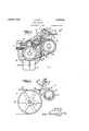
Fig. 2 is a side elevation of the device embodying the present invention.
Fig. 3 is a section taken on line 3-3 of Fig. 2.
Fig. 4 is a section taken on line i-l1 of Fig. 3.
Like reference characters denote like parts in the several figures of the drawings.
In the following description and in the claims parts will be identified by specific names for convenience, but they are intended to be as generic in their application to similar parts as the art will permit.
The present invention is described with particular adaptation to a cutting machine of the Langston type disclosed in U. S. Patents Nos. 1,664,119 and 1,359,076. In that type of machine, -an adjustable target or other member is disposed in the path ofthe advancing end of the material, and when actuated by contact with the material, releases a cut-olf mechanism for severing said material into selective lengths and permits movement of said cut-off mechanism through one cycle of operation.
Referring particularly to Fig. 1 there is shownan arrangement in accordance with the Langston Patents Nos. '1,664,119 and 1,359,076 in which there is provided a cutoff mechanism A, and a pair of feed rollers 5 B, which serve toadvance the material to be severed at a highl speed into the field of acti/on of said cut-off mechanism. The material is advanced along a conveyor system C until the advancing edge of said material comes in contact with a target D to actuate the latter. The movement of the target releases and starts the cut-off mechanism A with a resultant severance of the material. The cutoff completes its cycle and comes to rest. As soon as this material is cut, the conveyor system C propels the severed sheet away from the end of the body of the remaining sheet, at a speed sufficient to provide a gap or space between it andthe advancing uncut material, so that the target may drop into the space and be again actuated by the new end of the lbody of the material. This mechanism has been set forth and described merely vin order to indicate one suitable example of how the present invention can be adapted to a standard and well-known system of cutting such sheet-like material as stiff corrugated board. The present invention, however, is not intended to be limited in its adaptation to this form of cutting system for it will be hereinafter made apparent that it can be adapted to any other cutting system in which the sheets are propelled away from the field of action of the cutting means after being severed.
After the material has passed beyond the target units D its advancing edge comes into co-operative relationship with a speed reducing unit E. This unit E which constitutes the feature with which the present invention is particularly concerned serves to-reduce the speed of the sheet and deposit it on a table or v Stack support F.
The part of the conveyor system C which is illustrated in Figs. 2, 3 and 4 is supported by a pair of columns 1() supporting bearing blocks 11 secured by such suitable means as cap screws 12. The bearing blocks 11 support a guide bar 13 andaclutchtrip lever shaft 14, constituting part of the means vwhich coact with the target to cyclically actuate the cut-off mechanism A, as the advancing end of the uncut sheet comes into engaging relationship with the target D as more fully described in the patents hereinbefore referred to.
The bearing blocks 11 supporta shaft 15 having thereon, in interspaced relation, a plurality of pulleys 18 which support belts 19. These belts constituting the actuating part of the conveyor system C serve to advance the severed sheets at very high speed away from the field of action of the cutting means.
In the s ecic form in which thek present invention 1s illustrated there is disposed proximate the delivery end of the conveyor system C a rbller 20 which preferably comprises a metal tube 21 having a sheathing 22 of rubber or other yieldable material, and having press-fitted in the ends thereof or otherwise secured thereto stub shafts 23 and 24. The stub shaft 23 and the pulley shaft 15 have secured thereto a pair of sprockets 25, 25', which may be they same size and which are connected by a chain 26 whereby the roller is driven in the same direction as the belts, but as the pulleys 18 are larger thanthe roller, the latter will have a surface speed lower than that of the belts 19. It should be noted that the-roller` 20 has the top portion thereof extending above the operative plane of the conveyor. By this arrangement, the influence of the conveyor is reduced when the sheet is in co-operative relationship with the roller 20.
The bearing blocks 11 have parts 30 provided with guide channels 31 and carry brackets 32 providing bearing blocks for the shaft ends of the roller. The brackets may be vertically slidable in the guide channels 31 if desired, in which case they are provided `with elongated slots 33 receiving cap screws 34 threaded into the bracket parts 30. By means of this arrangement, these brackets 32 can be adjusted in selective vertical position with respect to the bearing blocks 11, and rigidly secured in adjusted position. Thus the elevation of the upper part of the slower speed roller above the plane of the upper run of the belts may be varied, if desired.
Integrally extending from each bracket 32 is a web plate 35 which serves to adjustably support a bearing block 37 adapted to hold a shaft 38. One of the blocks 37 iXedly supports one end of a stub shaft 39, the other end of which has secured thereto a device fortightening the chain 26, and permitting vertical adjustment of the roller. This arrangement preferably is shown as arm 40, one end of which terminates in a split clamp 41 whichl securely embraces the stub shaft 39 and which can be loosened to selectively adjust its angular position with respect to said stub shaft. The other end of the arm 40 is provided with a bearing block 42 in which is pinned, or otherwise fastened, a stub shaft 43. Loosely mounted on this stub shaft 43 is an idler sprocket wheel 44 which engages the chain 26 and which is confined against axial displacement between the block 42 and a collar 45 secured to the end of said stub shaft.
lSupported by the shaft 38 and co-operating with the roller 20 hereinbefore described are a plurality of guiding and holding members for directing the sheets to the roller and holding them thereon. These may take the form of interspaced split clamps 50 snugly embracing .said shaft and having integrally yextending from each one thereof a bracket 51.
Secured to each of said brackets 51 is a yieldable element such as the leaf spring 52, one end of which is curved upwardly to permitl the unobstructed advancement of the Isheets onto the roller 20, and the other end of which is disposed in co-operative relation with said roller. The springs 52 together with the roller can be adjusted vertically by shifting the bearing blocks 37 which carry the shaft 38. The angle of the guides 52 in respect to the direction of travel of the sheets as well as the downward pressure of the guides on the sheets 'may be varied by rotating the shaft 38. The rotation of the shaft 38 can be accomplished by any suitable means such as a handle 60 secured thereto. This may be secured in adj ustedposition by a yoke 61 having a segmental slot 62 receiving a locking screw 63. The hub of the handle and a collar 64. on the shaft 38 may coact with the opposite sides ofthe bearing 37 to prevent axially movement of the said shaft.
If desired a supporting and guiding member may be provided near the end of the conveyor system C so that the advancing end of the cut material will be sustained in its passage into contact with the roller 20. This supporting member may comprise a T-iron 66 having secured to the ange thereof a plate 67, the edge 68 of which is bent downwardly to obviate its interference With the advancing material.
In the operation of the machine, the material is cut by a suitable cut-off mechanism such as that described in the patents hereinbefore referred to. As soon as the material is severed the conveyor belts 19 carry the successive sections forward at a speed greater than that of the body of the sheetl to permit the next operation of the target. Each sheet as -severed is carried by the belts 19 at this higher speed until the advancing edge thereof comes in contact with the roller 20. This roller 20 is rotated with a peripheral speed less than the linear speed of the belts 19.
As the advancing edge of each sheet comes in contact with the rotating roller it will be slowed down while the rear edge thereof is urged forwardly at a speed corresponding to the speed of the belt 19. However, the springs 52 pressthe advancing materiall into intimate contact with the roller 20 so that the resultant speed of the said sheet is determined by the peripheral speed of said roller. This peripheral speed must be great enough, however, to permit the advancement of the sheet at a rate which is at least as great as the rate of the body of the uncut sheet in order to obviate the possible overlapping or abutting of successive sheets.
After the sheets have passed between the sprin 52 and the co-operating roller 20, they may ge deposited on a suitable delivery table F or other stack support. It should be noted that the reduction in speed of the advanced severed sheet effects a corresponding reduction in its momentum so that it can b e deposited lin a more orderly and organized fashion.'
If it is desired to change the speed with which the cut material passes through the field of action of the roller 20, it can be easily accomplished by adjusting the pressure of the springs 52 on said roller. This is elfected by shifting the bearing blocks of the roller or rockingthe shaft 38 in desired position as already set forth.
A'le certain novel features of the invention have been shown and described and are pointed out-in the annexed claims, it will be understood that various omissions, substitutions and changes in the forms and details of the device illustrated and in its'operation may be made by those skilled in the art without departing from the spirit of the invention.
I claim 1. In combination, a belt conveyor, a roller having its axis disposed below the operative plane of said conveyor, and having a portion extending above the plane, and means lf-or rotating said roller at a lower peripheral speed than the linear speed of the conveyor.
2. In combination, a belt conveyor including a plurality of co-axial pulleys, conveying belts supported thereby, a conveying roller disposed below and closely adjacent to said pulleys and having a portion extending above the operative plane of said belts, and means for rotating said roller at a lower peripheral speed than the linear speed of said belts.
3. In combination, a belt conveyor including a plurality of co-axial pulleys, conveying belts supported thereby, and a conveying roller closely adjacent to said pulleys and extending above the operative plane of said i belts, means for rotating said roller at a lower peripheral speed than the linear speed of said belts, and yielding means for pressing on to said roller, the sheets de'livered by said belts.
4. In combination, a belt conveyor including a pulley and a conveying belt, a roller closely adjacent to said pulley, and having the 4operating portion of its surface extending bove the operative plane of said belt, and a yiglding guide for pressing on to said roller the sheets delivered by said belt.
5. A sheet delivering mechanism, including a pulley, a. conveying belt supported thereby, a roller having a friction surface adjacent to the delivery end of said conveyin belt adjustable to vary the elevation thereo in respect to the operative plane of said belt,
ing a belt conveyor, a roller at the delivery end thereof and extending above theoperative plane of said conveyor, a shaft disposed above said roller, a plurality of flexible guiding and pressing members carried by said shaft, said shaft and roller being vertically adjustable.
7. A sheet delivering mechanism including a belt conveyor, a rol er at the delivery end thereof, and extending above the operative plane of said conveyor, a shaft disposed above said roller, a plurality of ilexible guiding and pressing members carried by said shaft, said shaft being mounted for oscillation to vary the effective action of said members.
8. An attachment for a sheet carrying belt conveyor including a roller positioned below and at the delivery end of the conveyor with a portion thereof projecting above the operative plane of the conveyor, and means for rotating said roller at a lower peripheral speed than the linear speed of the conveyor.
9. An attachment for a sheet carrying beltk conveyor, including a roller, means for supporting the roller with its upper portion eX- tending above the operative plane of the con- Veyor, and resilient means for pressing on to said roller the sheets delivered by said conveyor.
10. An attachment for sheet carrying belt conveyors, including a roller, means for supporting the roller with its axis at one side of the operative plane of the conveyor, and having its operating surface portiony extending to the opposite side of said operative plane, resilient means for pressing on to said roller the sheets delivered by said conveyor, and means for rotating said .roller from said belt conveyor but with a lower peripheral speed thaigthe linear speed of said conveyor.
Signed at Camden in the county of Camden, and State of New Jersey this 12th day of May, A. D. 1930.
. KARL SIEG.
Priority Applications (1)
| Application Number | Priority Date | Filing Date | Title |
|---|---|---|---|
| US452555A US1852590A (en) | 1930-05-15 | 1930-05-15 | Sheet delivery |
Applications Claiming Priority (1)
| Application Number | Priority Date | Filing Date | Title |
|---|---|---|---|
| US452555A US1852590A (en) | 1930-05-15 | 1930-05-15 | Sheet delivery |
Publications (1)
| Publication Number | Publication Date |
|---|---|
| US1852590A true US1852590A (en) | 1932-04-05 |
Family
ID=23796932
Family Applications (1)
| Application Number | Title | Priority Date | Filing Date |
|---|---|---|---|
| US452555A Expired - Lifetime US1852590A (en) | 1930-05-15 | 1930-05-15 | Sheet delivery |
Country Status (1)
| Country | Link |
|---|---|
| US (1) | US1852590A (en) |
Cited By (1)
| Publication number | Priority date | Publication date | Assignee | Title |
|---|---|---|---|---|
| US2467423A (en) * | 1945-03-19 | 1949-04-19 | George W Swift Jr Inc | Sheet delivery apparatus |
-
1930
- 1930-05-15 US US452555A patent/US1852590A/en not_active Expired - Lifetime
Cited By (1)
| Publication number | Priority date | Publication date | Assignee | Title |
|---|---|---|---|---|
| US2467423A (en) * | 1945-03-19 | 1949-04-19 | George W Swift Jr Inc | Sheet delivery apparatus |
Similar Documents
| Publication | Publication Date | Title |
|---|---|---|
| US4364552A (en) | Method and apparatus for forming a stream of partially overlapping paper sheets or the like | |
| US2101170A (en) | Sheeter | |
| US3700232A (en) | Sheet stacking apparatus | |
| JPS58132497A (en) | Device for cutting material of paper sheet | |
| US4330116A (en) | Bundling mechanism for signatures | |
| US3674258A (en) | Method and apparatus for feeding stacked sheet material | |
| GB2072078A (en) | Machine for cutting book blocks | |
| JP4871439B2 (en) | A device for depositing flat objects, which are individually carried, on a forward conveyor in an overlapped form | |
| US3493156A (en) | Adjustable outfeed assembly for stationery burster | |
| US6062556A (en) | Method and apparatus for merging sheets | |
| US2300625A (en) | Sheet feeding apparatus | |
| US4372201A (en) | Device for producing a bundle of paper sheets | |
| US4311090A (en) | Method producing a bundle of paper sheets | |
| US3274870A (en) | Means for cutting a web to produce overlapped sheets | |
| US2751981A (en) | Sheet forming and stacking apparatus | |
| US4204672A (en) | Device for conveying sheets within a sheet processing machine | |
| US2300863A (en) | Delivery apparatus | |
| GB1333093A (en) | Blank cutting apparatus | |
| US1852590A (en) | Sheet delivery | |
| US4144786A (en) | Envelope edge slitting apparatus | |
| US3735977A (en) | Method and apparatus for turning flat structures, especially newspapers | |
| US4300977A (en) | Machine for welding thermoplastic sheets | |
| US5086682A (en) | Band cutting apparatus | |
| GB919121A (en) | Improvements in or relating to delivery apparatus for delivering sheet material punched in punching machines | |
| US3072051A (en) | Sheet feeder for printing machine |