US1852568A - Train dispatching system for railroads - Google Patents
Train dispatching system for railroads Download PDFInfo
- Publication number
- US1852568A US1852568A US359040A US35904029A US1852568A US 1852568 A US1852568 A US 1852568A US 359040 A US359040 A US 359040A US 35904029 A US35904029 A US 35904029A US 1852568 A US1852568 A US 1852568A
- Authority
- US
- United States
- Prior art keywords
- relay
- wire
- contact
- energized
- circuit
- Prior art date
- Legal status (The legal status is an assumption and is not a legal conclusion. Google has not performed a legal analysis and makes no representation as to the accuracy of the status listed.)
- Expired - Lifetime
Links
Images

Classifications
-
- B—PERFORMING OPERATIONS; TRANSPORTING
- B61—RAILWAYS
- B61L—GUIDING RAILWAY TRAFFIC; ENSURING THE SAFETY OF RAILWAY TRAFFIC
- B61L7/00—Remote control of local operating means for points, signals, or trackmounted scotch-blocks
- B61L7/06—Remote control of local operating means for points, signals, or trackmounted scotch-blocks using electrical transmission
- B61L7/08—Circuitry
- B61L7/086—Common line wire control using relay distributors
Definitions
- FIG. 1 A 3+ F. B HITCHCOCK TRAIN DxsPA'irmuNG SYSTEM FOR RAILROADS Filed April 29. 1929 2/6, I VENT R 4 Sheets-Sheet 1 April 5, 1932. F. B. HITCHCOCK TRAIN DISPATCHING SYSTEM FOR RAIL-ROADS Filed April 29, 1929 4 Sheets-Sheet .mudi
- This invention relates to a train dispatching system of the type in which the dispatcher can control distant switch machines, in which trains are dispatched by wayside signal indications, and in which the control over the signals and switch machines, and the indication of the progress of trains, is transmitted over a comparatively few line wires, by apparatus of the synchronous selector 1:) type.
- the switch machines and signals which serve as a means to direct the trains must be under immediate control of the dispatcher.
- the time limit of this control must necessarily be reduced to a minimum value, when the dispatcher finds it advantageous to negotiate non-stop train meets, which is one of the advantages of a dispatching system applied in territory where excessive grades are prevalent.
- the OS indications be received by the dispatcher as soon as possible.
- This type of system also has the advantage, that further additions may be made to the system by simply adding more stations without altering the existing stations. If however,the central otlice, or dispatchers oflice, has rotary mechanisms to govern the control over the way-stations, then it is necessary that the rotary mechanisms be built with spare spaces or replaced by new mechanisms in case of further extension of the system.
- a self stepping synchronous selector system which is entirely operable through the use of properly designed relay mechanisms, control levers and indicators, and having the OS and control impulses transmitted over a certain required number of message channels successively set up, so that the dispatcher from a. central office may have control over the switch machines, signals, de-rails and the like, and receive OS indications, within the territory over which he has control.
- the OS indications shall be picked up, as each station is successively under control, and the message channels used for control impulses shall be set up only at such time when a control lever has been moved to a new position, with such message channels established by the simultaneous operation of a group of relays at the dispatchefls ofiice and a group of relaysat the way-station to which the control impulse is to be transmitted, which groups of relays shall operate to set up the required message channel.
- the operation of these groups of relays which set up the message channels for control impulses shal l'be effected by the transmission of a plurality of alternate positive and negative impulses over-the stepping circuit, including the stepping wire and the common return wire, of which each impulse will energize and move one of the above mentioned relays in the dispatchers office and one in the way-station under control, during which period of time that exists between the movement of two successive relays, a control impulse from the dispatchers ofiice may be transmitted over the message channels thereby set up.
- the present invention also includes means whereby the system shall be normally at rest, and may be initiated, either by the movement of a control lever at the dispatchers ofiice to a new position, or by the changing of the position of a track relay at any way-station.
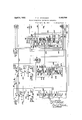
- Fig. 1A and Fig. 113 when placed end to end, illustrate conventionally the equipment in the dispatchers oifice for automatically shifting the control of the dispatcher from one way-station to the next in rapid succession, and automatically stopping it at a waystation to which a control impulse is to be transmitted, and automatically and sequentially operating the channel selecting relays at that station to set up the required message channel;
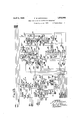
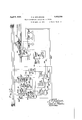
- Fig. 1C illustrates conventionally the equipment of one way-station with the apparatus shown connected conventionally to control relays which have control over the switch machine and signals located at the west end of apassing siding;
- Fig. 1D represents the equipment at a Waystation similar to the way-station shown in Fig. 10 but connected so that control may be established over the east end of a passing siding; also, showing the equipment at a Waystation for transmiting an OS indication at a permissive signal of an absolute-permissiveblock signal system.
- the dispatcher controls the switch machines and wayside signals of a large portion of a railway'system, possibly including many passing sidings, diverging routes, draw bridges, railway crossings, and the like
- the present invention has for convenience been shown as applied to the apparatus located at the east and west ends of the passing siding PS and at a permissive block signal SW7 (see Figs. 1C and 1D).
- the passing siding PS connects to a main track, having sections TK TK TK and TK of a single track railway system signalled with absolute-permissive-blocksignalling, except at track sections, such as sections TK and TK which are under the control of the dispatcher.
- the track sections TK and TK contain track switches TS and TS respectively, which have associated therewith the usual detector track circuits.
- Track section TK including a fouling track section F55 is enclosed by insulated joints 1 and 2.
- the track section TK including a fouling track section FS is enclosed by insulated joints 3 and 4:.
- the track section TK belongs to the regular absolute-permissive-block signal system and is separated from the rest of the track by insulated joints 4 and 5.
- These track sections TK TK and TK have track batteries 6, 7 and 8 respectively, associated therewith, to supply energy to 1gheir respective track relays TR TR and T
- the starting signals for the main track and siding at the west end of the passing siding PS have been designated SWV and SW respectively, and at the east end of the passing siding PS have been designated SE and SE respectively.
- At the west end of the passing siding PS is the main line signal and the take siding signal, SE and SE respectively and at the east end of the passing siding PS is the main line si nal and the take siding signal SW and SW respectively.
- the permissive signal SW is located at the east end of the track section TK In the dispatchers o'liice, is preferably located a miniature track layout (see Fig.
- This miniature track layout has indicating lamps P, P, 1 associated therewith, which if illuminated, indicate the occupancy of the corresponding track circuits, namely, the track circuits of track sections TK TK and TK respectively.
- the track switch TS at the west end of the passing siding PS is preferably controlled by the switch machine relay SMR which relay is in turn controlled by the lever SML through the medium of the self step ping synchronous system hereinafter described.
- the signals SE SE SW and SW are controlledgby the signal relay SR and the direction relay DB through the medium of the synchronous selector system in accordance with the position of the lever SL located in the dispatchers ofiice.
- the track switch TS and the signals SE SE SW and SW are likewise controlled in accordance with their respective control lever SML and SL in the dispatchers ofiice.
- the manner, in which such relays, as relays SMR DB SR may control their respective functions, is fully set forth in pending application by S. N. Night, Ser. No. 321,185, filed Nov. 22, 1928.
- the dispatchers office contains a number of relays, so grouped and inter-related in their respective functions, as to accomplish the operation of the system automatically. Thesevarious functions of the relays involved, serve to give them distinctive group names and distinguishing reference characters.
- the group of relays 1 2 and 3 are the control impulse message channel selecting relays for the first way-station, in which the order of the number gives the order of se quent-ial operation for that station, and the order of the exponent gives the order of the station.
- the group of relays 1 2 and 3 are the controlimpulse message channel selecting relays for the second waystation, with the reference characters having a like meaning.
- the energizing circuits for these groups of message channel selecting relays are repeated by the line relay L and the particular group to be operated is selected by the station selecting relays ST ST and ST in which the exponents represent the order of the way-station to which they are assigned.
- the initiatin relay IN and the control relay CR serve to initiate and control the duration of the sequential operation of the system respectively, in transferring the control of the dispatcher from one way-station to the neXt way-station, having associated therewith the cycle checking relays (HQ and (3K which control the relays 1N and GR'in such a manner, that the system shall complete two cycles of non-mechanical rotation, after each time that the initiatingrelay IN" has been energized.
- the transfer impulse generating group is composed of an operating relay OPR, the control checking relays CC, CC and CS the impulse polarity relays N and P, and the re-set relay RE. Also, the stepping impulse generating group is composed of the master relay MR, and two time spacing repeater relays S and S.
- This stepping impulse generating group has associated therewith the starting relay ST and the stopping relay STP.
- the control of the stepping impulse generating group and associated relays is determined by the group selecting relays G and G which are in turn controlled by the movement of a control lever effected by the dispatcher.
- an added transfer relay is placed in series with the line as well as an added amount of line wire.
- a transfer relay TRAN serves to repeat in the dispatchers ofiice the conditions imposed upon the transfer control wire.
- An indicator lamp I is included at the dispatchers office, to indicate such time that the transfer relay ceases to function, due to an opening in the transfer control wire.
- An automatic cut-out A is inserted in the transfor control wire circuit, which serves to open the said circuit, in case an excessive current flows through said cut-out A".
- This cut-out A also has associated therewith an ampere meter M and furnishes a means whereby the operator may ascertain approximately where there is a short upon the transfer control wire.
- a transfer trouble switch TTS is furnished, which provides a means whereby the operator may regulate the transfer control circuits in such a manner that the system may be operated automatically to the certain point in the system at which the known trouble occurs.
- Suitable power supply, for the transfer control impulses is provided by the batteries BT and BT connected together to give negative and positive potentials respectively, in respect to the central point of the batteries connected to the common wire.
- the stepping impulse power supply is furnished by the batteries BT and BT and are connected to give positive and negative potentials respectively, in respect to the central point of the batteries connected to said comm'on wire.
- Various other points in the circuits which require positive and negative potentials in respect to said common wire are indicated as (13+) and (B) respectively, which in the dispatchers office, may be battery BT or BT' or other separate sources.
- the indicated sources for the waystations are separate batteries at each waystation, which give positive or negative potentials in respect to said common wire, and are maintained charged in any suitable manner such as some trickle charge method.
- the dispatchers ofiice is connected to the way-stations (see Figs. 16 and ID) by four line wires, consisting of a common wire 200, a transfer wire 201, a stepping wire 202, and av message wire 203.
- the way-station shown in Fig. 1C as connected to'the west end of a passing siding PS, is identical to the way station shown in Fig. 1D as connected to the east end of the same passing siding PS.
- the way-station shown in Fig. ID as located at the permissive block signal SW has transfer as well as effecting the tequipment identical with the other two waystations shown, but with the control impulse message channel selecting relays omitted.
- the relays duplicated in the several stations have like reference characters with suitable exponents distinguishing the station to which they belong. Thus. only the way-station shown in Fig. 1C will be briefly described.
- This way-station shown in Fig. 1C has a transfer relay THANK of the polar neutral type which controls in turn and sequentially the station selecting relay S and the station shunting relay SS These relays composing the transfer group, give control over the message channel selecting rela s A B and C to the next way-station, The energizing circuit of the message channel selecting relays, is repeated by the line relay L when the transfer group has selected this particular station.
- An OS storing relay USS is provided to hold the OS indication until the initiating relay 1N has initiated and operated the synchronous selector system up to this waystation, so that the said US indicationcan be registered at the dispatchers oflice.
- the relays L L L OPE, and MR are of the biased to neutral type of polar relay. In other words, their armatures move ac cording to the polarity applied due to the permanent magnet incorporated, but assume a neutral position when de-energized.
- Other polar relays are of the polar permanent magnet stick type which respond to an energy impulse of a certain polarity by moving its contacts to a position determined by that polarity, due to a permanent magnet which is incorporated within the relay. This permanent magnet holds the armature when moved to an extreme position even though the relay is then (lo-energized.
- the neutral relays incorporated within the circuits of the system are of the usual type and are shown conventionally with heavy line bases in such cases where they have a slow releasing period.
- Lever SML has connected to it by mechanical means contact 9 which moves to its dotted line position when the lever EMT is moved to its dotted line position.
- the lever SL has connected to it by mechanical means the contacts 10 and 11, which move to their right hand dotted line positions with the movement of the lever SL to a left hand dotted line position with corresponding opposite movements with lever SL moved to a right hand position.
- the levers SML and SL have associated therewith corresponding contacts 12, 13 and 14 respectively.
- a before selection condition which is set up immediately after the atrest period, which before selection condition determines that all the way stations shall be idle except the first way station which is tobe under control;
- condition which is used for the at rest period and for initiation is the same condition which resets the way stations to a normal at rest condition.
- the initiating relay 1N and control relay OR are de-energized, completing' a circuit for the re-set relay RE, which, when energized, places negative potential upon the transfer wire'201, energizing the transfer relays TRAN", TRAN TRAN and TRAN so that their polar contacts are in a negative position and their neutral, contacts are in an energized position.
- the station shunting relays SS SS and SS are also energizech
- the circuit for relay RE is traced as follows :from positive terminal of indicated source having suitable potential, through relay RE, wires 15 and 16, back contact 17 of relay OR, to the common wire 200.
- the circuit for placing negative potential upon the transfer wire 201 is traced as follows :negative potential from the battery BT through wire 18, front contact 19, wire 20, transfer wire 201, transfer relay TRAN", transfer wire 201 to the first way station, transfer relay TRAN through the transfer wire 201 to the second way station, transfer relay TRAN through the transfer wire 201 to the third way station, transfer relay TRAN to the common wire 200.
- relay SS is energized through the circuit traced as follows from positive terminal of indicated source having suitable potential, through the relay SS wire 21, wire 22, front contact 23 of relay TRAN wire 24, negative contact 25 of relay TRANQ to the common wire 200.
- relay SS is energized through the circuit traced as follows from positive terminal of indicated source having suitable potential, through the relay SS wire 21, wire 22, front contact 23 of relay TRAN wire 24, negative contact 25 of relay TRANQ to the common wire 200.
- the occupancy of track section TK shunts the track relay TB so that its contact 26 assumes a ole-energized position, which sets up an energizing circuit for the OS storing relay OSS through a circuit traced as follows :from negative terminal of indicated source having suitable potential,
- relay OSS a momentary energizing circuit for the relay IN is completed, being traced as follows 7 from positive terminal of indicated source having suitable potential, through relay 1N Wires 28 and 29, make before break contact 30, to the common wire 200.
- the relay IN is energized, a stick circuit is completed for both the relays 1N and OSS
- This stick circuit for the relay 1N is traced as follows :from positive terminal of indicated source having suitable potential, through relay OSS wire 94, front contact 46, wire 29, front contact 96, wires 169 and 31, front contact 32 of relay SS to the common wire 200.
- the initiating relay IN and the control follows relayOR, in the dispatchers oifice, are now energized through a circuit completed by the energization of the relay 1N in the third way station, which circuit is included at each way station having identical and symmetrical connections, so that the system may be initiated from each and every way-station where OS indications occur.
- This initiating circuitforthev thirdw'ay station is traced as i from positive terminal of indicated source having suitable potential, through upper winding of relay OR, wire 33, relay 1N wires 34, 35 and'36, back contact 37 of relay 8T wire 38, back contact.
- relay ST wire 40 back contact 41 of relay 8T to the message wire 203 which is connected to each way station, from the message wire 208 at the third Way station through wire 42, front contact 43. and negative contact 44 of relay TRAN wire45, front contact 95, to the common wire 200.
- relays N and]? operate to alternately place positive and negative impulses upon the operating relay OPR, whichin turn sequentially operates thestation selecting relays STl, ST and ST
- the energizingcircuits of the relay OPR are-carried through the-relay CO in such a manner that the contact 72 of relay OO assumes a position which is in accordance withthe'energization of. either relay N or relay P, and in accordance with the polarity of the potential applied to the relay OPE.
- the energizingicircuit for the re-set relay RE is broken at contact 17 of relay OR.
- the front contact 47 ofrelay IN closes a stick circuit for relay IN", being traced as follows :--from positive terminal of indicated source having, suitable potential, through upper Winding of relay CR, wire 33, relay, TN", wires 34' and 35, front contact 47,
- relay OR closes a circuit for energizing the relay Pbeing traced as fol.- lows:from positive terminal of indicated source having suitable potential, through front contact 53 of relay OR, wires 54 and 55, relay P, wires 56, 284 and 285, front con tact 57, wire-58, back contact 59 of relay 81, wire 60', back contact 61 of relay ST wire 62, back contact 63 of relay.
- relay P closesits stick circuit, being traced as follows :from positive terminal of indicated source having su1table potent1al, front "contee tact 53 of relay OR, wires 54 and 55, relay P, wires 56, 284 and 286, front contact 64 of relay l ire 65, back contact 66 of relay N, to the common wire 200.
- the energization of relay P places positive potential on the relay OPE through a circuit traced as follows:from the positive terminal of indicated source having suitable potential, through upper winding of relay wire 67, back contact 68, wire 69, front contact 70, wire 71, through relay OPE, to the common wire 200.
- the current that flows in this circuit just traced energizes the contact 72 of relay CO to a positive position, and the contacts 73 and 74 of relay OPR to a positive position.
- the de-energization of the slow releasing relay RE opens the energizing circu of the transfer relays 'lRAN TRAN Than 2 and TRAN at the front contact 19 of relay RE, as the slow releasing period consumes enough time to permit the relays SS SS and SS to become fully de-ener' ized before a positive potential is placed upon the transfer wire by the contacts of relay OPE being in a positive position.
- This de-energization of the station shunting relays SS SS and accomplished the sectionalization of the transfer line wire 201 by shunting the transfer wire at each station on the side of the trans fer relay away from the dispatchers ollice, to the common wire 200.
- relays TRAN and SS reroute the stick circuit of the relay OSS through aback contact of relay TRAN his stick circuit of relay OSS is traced as follows:from positive terminal of indicated source having suitable potential, through relay OSS wire 94, front contact 46 of relay OSS wire 29, front contact 96 of relay 1N wires 169 and 293, back contact 170 of relay TRAN Wire 171, negative contact 172 of relay TRAN to the common wire 200.
- relay RE assume a fully (ls-energized position, positive impulse being placed on the relay OPE, a circuit is completed which places positive potential upon the tra sfcr wire 201.
- Positive potential upon the transfer wire 201 energizes the relays THAN and TRAN in such a manner that the polar contacts are energized to a positive position before their neutral contacts assume an energized position, which is the natural characteristic of polar neutral relays.
- the relay SS cannot be picked up, hence the transfer relays TRAN and TRA ⁇ are shunted out of the transfer line circuit.
- relays S is energized as soon as the natural contacts of said relay TRAN have assumed an energized position.
- the energization of relay S permits the energization of relay SS When the relay TRAN is de-energized.
- the relays S and SS are energized and held in energized positions through their own stick circuits, which are not broken until the transfer relay 'lRAN has been again energized With a negative impulse.
- the operation and function of the transfer group at other Way stations is identical With the operation and function of the transfer group at the first Way station.
- the circuit for placing the positive potential upon the transferred Wire 201 is traced as follows :from the positive terminal of battery BT through the resistances VRR and VRR", through the automatic cut-out A", back contact 75, Wire 76, positive contact 73 of relay ()PR, to the transfer Wire 201 through transfer relay TRAN", transfer Wire to the first Way station, through transfer relay TRAN to the common Wire 200.
- This positive impulse energizes the transfer relays TRAN and TRAN so that their polar contacts assume a positive position and their neutral contacts assume an energized position.
- the station selecting relay ST is energized completing a stick circuit, which is traced as follows :from positive terminal of indicated source having suitable potential, throughfront contact 88 of relay 8T relay ST Wire 82, through a circuit heretofore traced to the common Wire 200.
- the cycle checking relay CK is energized at the same time that'the station selecting relay ST is energized, due to the fact, that both energizing circuits are carried through the positive contact 87 of relay TRAN".
- This circuit which energizes the relay CK also holds, it in an energized position until the first cycle has been, completed, as Well as furnishing the energy for the stick circuit of the relay IN".
- This energizing circuit of relay CK is traced as follows :from positive terminal of indicated source having suitable potential, through relay (1K Wire 163, front contact 16%, wires 167, 165, 215 and 86, positive contact 87 of relay TRAN to the common Wire 200.
- the stick circuit for the relay IN is traced as follows :from the positive terminal of indicated source having suitable potential, through upper Winding of relay CR, Wire 33, relay TN", Wires .341 and 35, front contact 47 of relay IN", Wire 48, front contact 49 of relay CK Wire 163, front contact 164 of relay IN, Wires 167, 165, 215 and 86, positive contact 87 of relay TRAN", to the common Wire 200.
- the station relay S at the first Way station is energized due to the energization of the transfer relay TRAN
- the relay S is energized through a circuit traced as follows z-from positive terminal of indicated source having suitable potential, through front contact 89 of relay TRAN Wire 90, relay S Wires 91 and 290, positive contact 25 of relay TRAN to the common Wire 200.
- a circuit traced as follows z-from positive terminal of indicated source having suitable potential, through front contact 89 of relay TRAN Wire 90, relay S Wires 91 and 290, positive contact 25 of relay TRAN to the common Wire 200.
- a message circuit is completed which allows the OS indication at the first Way station, shown in Fig. 1G, to be transmitted to the dispatchers oflice.
- This message channel is traced as follows :from negative termina-l of indicated source having suitable potential, through hack contact 156 of relay OSS Wire 97, back contact 98 of relay A Wire 99, back contact 100 of relay B Wire 101, back contact 102 of relay C Wire 103, back contact 104 of relay SS Wire 105, front contact 106 of relay S Wire 107, positive contact 108 and front contact 109 of relay TRANE Wire 280, to the message Wire 203, to
- relay CS The polar contact of relay CS is thus energized to a negative position, allowing the indicator lamp I to remain unilluminated, indicating to the dispatcher that there is no train occupying the track section TK
- the relay ST becomes energized, a circuit is completed, energizing the relay N which opens the stick circuit of relay P, closes its own stick circuit, and closes a circuit Which will place negative potential upon the relay OPR as soon as the sloW releasing relay P reaches a de-energized position.
- This energizing circuit for the relay N is traced as follows :from the positive terminal of indicated source having suitable potential, through front contact 53 of relay CR, wires 54 and 175, relay N, wires 176, 177 and 178, back contact 179, wire 180, and 181, front contact 182 of relay ST wire 60, back contact 61, wire 62 and 185, back contact 63 to the common. wire 200.
- the stick circuit for the relay N is traced as follows :from positive terminal of indicated source having suitable potential,front contact 53 of relay CR, wires 54:,and. 175, relay N, wires 17 6 and 177, front contact 186 of relay N, wire 187, front contact 188 of relay P, to the common wire 200.
- relay SS there is a period of time between the end of the first positive impulse placed upon the transfer wire 201 and the beginning of the second positive impulse allowing sufficient time for the relay TRAN to become deenergized thus picking up the relay SS
- the cnergization of relay SS allows the second way station to be selected as soon as the succeedingpositive impulse is applied.
- the relay SS is energized through a circuit traced as follows :from positive termi nal of indicated source having suitable potential, through relay SS wires 21 and 22, front contact 117, wire 118, back contact 119, to the common wire 200.
- the relay SS is energized which completes a stick circuit traced as follows :from positive terminal of indicated source having suitable potential, through relay SS wire 21, front contact of relay SS wire 121, front contact 122,
- the contacts 73 and 74 of relay OPE are energized to a negative position, thus, placing a positive impulse upon the transfer wire 201, and also a positive in'ipulse on wire 127 energizing the relay 3T through a circuit raced as follows from positive terminal of indicated source having suitable potential, through positive contact 77 and front contact 78 of relay TRAN", wire 79, negative contact 74, wire 127, front contact 128 of relay 81, wire 129, relay ST wires 288 and 287, back contact 85, wires 289, 215 and 86, positive contact 87 of relay TRAN to the common wire 200.
- relay S With the contact 73 of relay OPR in a negative position, a positive impulse is placed on the transfer wire 201 energizing the rele ys TRAN and TRAN? Vith relay TRAN energized, the relay S is energized through a circuit identical, with the energizing circuit of relay S heretofore traced. It is likewise, in. a similar manner held in an energized position through a stick circuit.
- a message channel is set up which allows the ()Sindication of the econd way station to be transmitted to the dispatchers oiiice.
- This message channel is traced as follows:-from negative terminal of indicated source having a suitable potential, through back contact 132 of relay OSS wire 133, back contact 134 of relay A wire 135, back contact 136 of relay B wire 137, back contact 138 of relay wire 139, back contact 1400f relay SS wire 1&1, front contact 142 of relay S wire 1&3, positive contact 1 1 1, and front contact 145 of relay TRAN wire to the message wire 203, to the dispatchers ofiice, back contact ll of relay 8T wire l0, front contact 39, wire 1 13, back contact 14.7, wire 148, back contact 149, wire 150, back contact 151, wire 152, relay CS to the common w se 208.
- the relay G3 has its polar contact energized. to a negative position, le .ving the indicated lamp I un
- relay 5T becomes energized circuit
- the energizing circuit for the relay P is traced as follows :from positive terminal of indicated source having suitable potential, through front contact 53 of relay CR, wires 51 and 55, relay P, wires 56, 189 and 190, baclz contact 191 of relay G wires 193 and 19 front contact 195 of relay ST wire 185, back contact 63 of relay S1, to the common wire 200.
- the relay SS is energized, through a circuit being exactly symmetrical with the circuit described for the relay SS l l hcn the positive potential is placed on the relay OPE, its contacts 73 and 7 1 assume positive posit-ion and a positive impulse is placed on the transfer wire 201 and on the wire 80.
- the station selecting relay ST is energized and he transfer relay 'Ql-ZAll at the third way station is energized.
- the relay ST is energized through a circuit traced as follows :from positive terminal of indicated source having suitable potential, through positive contact 77, and front contact 78 of relay TRAN", wire 79, positive contact 7 4 of relay OPR, wire 80, front contact 153, wire 154, relay ST wires 166 and 86,positive contact 87 of relay TRAN", to I the common wire 200.
- the energization of relay 8T closes a stick circuit through front contact 155.
- the energization of the relay TRAN energizes the relay S through circuits exactly symmetrical as traced for relay S As the relays ST and S simultaneously assume energized positions, a message channel is compl ted for transmitting an OS indication from the third way station to the dispatchers ofi'ice.
- the message channel for the OS of the third station is traced as follows :-from the positive terminal of indicated source having suitable potential, through front contact 156, wire 15?, back contact 158 of relay SS wire 159, front contact 160 of relay S wire 161, positive contact 44: and front contact 13 of relay TRAN- wire 42, to the message Wire 203 to the dispatchers oflice, front contact 41, wire 162, relay OS to the common wire 200.
- the relay US has its polar contact energized to its positive position, illuminating the indicator lamp I with suitable potential as is obvious from the accompanying drawings.
- I-Ience the presence of the train upon the track section TK is transmitted to the dispatchers oiiice and indicated to the dispatcher by the illumination of indicator lamp I
- the relay TRAN is energized with a positive impulse the stick circuits for the relays OSS and IN as heretofore traced, are broken.
- the OS indication must be transmitted, which requires that the releasing time of an OS storing relay, and relay OSS in particular, must have a release period greater than the sum of the pick up periods of the relays TRAN and S Also, the relay IN must have a release pe riod less than the sum of the pickup periods of the relays TR AN and S and greater than the drop away period of the relay TRAN?
- the relay IN when the system is at rest, the relay IN has a stick circuit, (as heretofore traced) which is closed through front contact 32 of relay SS but when the system is initiated and begins operation the neutral armature of relay TR AN drops away closing the stick circuit of relay 1N through back contact 170 of relay TRAN and opening the stick circuit at front contact 32 of relay SS
- the relay SS is slightly slow releasing so that, as the stick circuit for relay SS when the system is at rest is closed through front contact 170 of relay THANK and the stick circuit of relay IN is closed through the said back contact 170, then the time consumed by the contact 170 to change from an energized to a de-energized position is consumed by the release period of relay SS But to insure that the relay IN shall not drop away in case the release period of SS was not sufficiently long enough, the relay 1N should have a release period greater than the release period of relay TRAN Now as the control is transferred from one way station to another way station, the stick circuit for the relay IN is opened as soon as the contact
- the release period of relay Ihl is less than the sum of the pick up periods of relay TRAN and S there is sufficient time allowed in the rel-ease period of relay TRAN and the pick up period of relay SS to insure that the relay IN is entirely dropped away. Also, as soon as control is transferred from this way station, the stick circuit for relay IN is closed at the contact 32 of relay SS that should the OS-ing conditions change, the circuits would again be ready to stick relay IN energized.
- the transfer relay TRAN has the same operating time characteristic as all other transfer relays and that the station selecting relays 8T ST and ST have the same operating characteristics as the relays S S and S
- the slow release periods of the relays N and P allow plenty of time for the transmission of OS indications, as corresponding station selecting relays and station relays have been energized before another condition is set up, even through the station selecting relays immediately close circuits to positively cause the next condition in sequence to occur.
- relay ST With the energization of relay ST a circuit is closed for energizing the re-set relay RE.
- This circuit for energizing said relay RE is traced as follows:from positive ter minal of indicated source having suitable potential, through relay RE, Wires 15 and 173, switch TTS in its present normal position, wire 174:, front contact 63 of relay ST to the common wire 200.
- the energization of the re-set relay RE places negative potential upon the transfer controlwire 201, which energizes the polar contacts of all transfer relays to a negative position and their neutral contacts to an energized position establishingthe' atrest condition for the Way stations; only.
- the voltage regulating relays VR and VB are energized by thexenergization of station selecting relays ST and ST respectively.
- the relay VR is energized through a circuit traced as follows :from the positive termlnal of indicated source having suitable p otentlal, through relay VH wire 183, front contact 182 of. relay ST wire 60, back contact 61 of relay ST wires 62 and 185, back contact 63 of relay ST to common wire 200.
- the energizing circuit. for the relay VH is traced as follows :from positive terminal of indicated source having suitable potential, through relay V11 wire 196, front contact 195 of relay ST", wire 185, back contact 63 of relay ST to the common wire 200.
- the second cycle of operation is the same the first cycle, except the energization of the cycle checkingrelay 0K which takes place immediately upon the energization of the relay TRAN" for selecting the first way station.
- the relay IN is (ls-energized, so that a circuit is completed for energizing the relay CK as soon as the relay TRAN" has become energized.
- This circuit for energizing relay 0K is traced as follows :positive terminal of indicated source having suita le potential, through relay CK", wire 211, back contact 16% of relay IN", wires 167, 165, 215 and 86, positive contact 87 of relay TRAN" to the common wire 200.
- relay CK Re-rot1tes the stick circuit of the relay CR, which is traced as follows :from the positive terminal of indicated source having suitable potential, through the lower winding of relay CR, front contact 50 of relay CR, wire 51, front contact 52 of relay CK", wires 168, 165, and 86, positive contact 87 of relay TRAN", to the common wire 200.
- the lever SML is moved to a left hand position, during the movement of which, the contact 12, mechanically connected to lever SMIF, completes a momentary circuit for energizing the relay G
- This momentarily made circuit- which is completed when any control lever for the second way station is moved to new position, has two functions, namely, first to register that a control lever for that particular way station has been moved to a new position, which is accomplished by the energization of a group selecting relay, such as relay G second, to initiate the system, which is accomplished by having make-before-break contacts on the group selecting relay controlling circuits in such a manner, that, when said group selecting relay is energized, that these make-before-break contacts momentarily complete a circuit for energizing the initiating relay 1N and the control relay OR.
- the system With the initiating relay 1N and the control relay OR, both energized, the system operates to transfer the dispatchers control from one way station to the next way station in the usual manner, until the way station is reached to which a control impulse is to be transmitted, which station, is determined by the energization of its group selecting relay, which in this particular case is relay G After the station selecting relay ST is energized, a potential would ordinarily be placed on relay P for effecting the transfer of control to the next way station.
- relay G With relay G energized, this potential does not go to relay P, but is given to the starting relay ST", which causes the stepping impulse group to operate and place alternate positive and negative impulses upon the stepping line 202, which cause the relays 1 2 and 3 in the dispatchers office to operate sequentially and in synchronism with the relays A 13 and O at the second way station. As soon as these relays have completed their sequential operation, the relay 3 completes a circuit for energizing the stopping relay STP, which causes the stepping impulses to immediately cease.
- apotential is placed on either relay CO or relay CO depending upon the position of contact 7 2 of relay CO, which contact is in a position as determined by the polarity of potential then placed upon relay OPE for selecting the way station then under control.
- the potential is placed upon the relay CO in this particular illustration, due to the contact 72 of relay CO being in a negative position, which energizes the contacts of relay CO so that its stick circuit is closed, as well as a circuit for energizing the relay P.
- This circuit for energizing the relay P is continued, until the next way station has been selected, at which time the system operates to select further way stations in the normal OS-scanning manner as heretofore described.
- the stopping relay STP instead of-re-routing the potential, which holds the starting relay ST energized, to effect the next transfer impulse, it is cut off by the stopping relay STP so that said potential will produce the energization of relay ST during the second cycle of operation.
- the second cycle of operation is similar to the first, at the end of which the control relay OR is de-energized, which opens the stick circuit for the group selecting relay G During the dc-energization of relay G a momentarily made circuit re-energizes the initiating relay IN". This causes the system to further operate through two complete cycles, insuring that all control inclications and OS indications have been brought up to date, which is particularly desirable in systems where OS indications giving. the positions of controlled mechanisms are used.
- the lever SML being moved to a left hand position, results in a momentarily made circuit for energizing the relay G being traced as follows :from the positive terminal of indicated source having suitable potential, through relay G wires 215 and 216, contact 12, to the common wire 200.
- the energization of relay G results in a momentarily'made circuit for en ergizing the relays INand OR, which may be traced as follows :from positive terminal of indicated source having suitable potential, through upperwind of relay CR, wire 33, relay IN", wires 34, 217 and Y218, make before break contact 219, to the common wire 200.
- relay G As the momentarily made circuit for energizing the relays IN and OR, is completed while the relay G is but partly energized, and also relay Or is slightly slow releasing, then the relay CR has time to reach an energized position to close the stick circuit for relay G being traced as follows :from' positive terminal of indicated source having suitable potential, through relay G wire 223, front contact 220, wires 221 and 222, front contact 17 of relay OR, to the common wire 200.
- the system is initiated as heretofore described, and the system operates to select the first way station, automatically picking up the OS indication at that way station, and automatically leaving the first way station to place control over the second way station.
- the auto matic control of the system is identical with the operation heretofore described.
- the OS indication is transmitted to the dispatchers office indicating that the track section TK is still unoccupied, during which time, the energization of relay ST in the dispatchers office has completed a circuit for initiating the impulses to be placed upon the stepping wire 202, used to operate the control impulse message channel selecting relays.
- a circuit is completed for energizing the relay ST instead of transferring to the third way station, because the relay G is energized and remains energized through its stick circuit.
- This circuit for energizing relay ST is traced as follows :from positive terminal of indicated source having suitable potential, through relay ST wire 22?, back contact 223 of relaySTP, wires 229 and 224, front contact 191 of relay Gflwires 193 and 194, front contact 195 of relay 3T wire 185, back contact 63 of relay 8T to the common wire 200.
- relay ST places potential upon the relay MB in accordance with the position of relay 'S which is in a position in accordance with the position of relay S",
- the relay MR places positive potential upon the stepping wire 202 through a circuit traced as follows :from positive terminal of battery BT3, throughpositive contact 231 of relay MR, wire 232, relay S, wire 2'33, relay L through the stepping wire 202 to the first way station, through Wire 234, front contact 235 of relay SS wire 236, through the stepping wire 202 to the second way station, through relay L wire 237, back contact 238 of relay SS to the common wire 200. It is assumed that the relay S responds to the positive impulse and relay S is energized with a negative impulse, thus energizing relay MR with a negative impulse, as explained in application Ser. No.
- the stepping impulses placed upon the stepping wire 202 are repeated by the line relayL in the dispatchers ofiice, and by line relay L at the first way station, when the first way-station is selected for control impulses.
- the line relay L repeats these stepping impulses but the line relay L does not operate due to the fact that it is shunted out through a circuit heretofore traced. It is thus seen, that whenever a station is selected for receiving control impulses, the relays S and L operate in series with the line relay of the particular way station then selected.
- relay S1 selects the control impulse message channel selecting relay bank composed of relays 1 2 and 3 so that they are sequentially operated when the line relay L is operated. Also, when the relay ST is energized the control impulse message channel selecting relay bank composed of relays 1", 2 and 3 are sel cted so that they operate sequentially when the line relay L is operated.
- the station selecting relay ST selects the message channel relay bank of way station one, and the station selecting relay bank ST selects th message channel selecting relay bank for way station two.
- relay ST As the relay ST is now energized and the contact 239 of relay L" moves to a positive position then a circuit is completed for energizing relay 1 being traced as follows from positive terminal of indicated source having suitable potential, through positive contact 239 of relay L wires 248 and 249, back contact 307 of relay 2 wire 306, through relay 1 wire 250, back contact 251, wires 252 and 253, back contact 254, wires 255 and 256, front contact 61 of relay ST wires 62 and 185, back contact 63, to the common wire 200.
- relay 1 With contact 294 of relay 1 in an energized position, a stick circuit is closed for said relay 1 being traced as follows :from positive terminal of indicated source having suitable potential, through front contact 294, wire 295, relay 1 wire 250, back contact 251 of relay 2 wires 252 and 253, back contact 254, of relay 3 wires 255 and 256, front contact 61 of relay ST, wires 62 and 185, back Contact 63 of relay ST, to the common wire 200.
- the relay A at the second way station is energized by the movement of contact 240 of relay L to a positive position, through a circuit traced as follows :from positive terminal of indicated source having suitable potential, through positive contact 240 of relay L wire 310, back contact 311 of the relay B wires 257 and 297, through relay A wire 259, back contact 260, wires 261 and 262, back contact 263, wires 264, 265 and 266, positive contact 267, to the common wire 200.
- a stick circuit is closed for said relay A being traced as follows :from positive terminal of indicated source having suitable potential, through front contact 296 of relay A wire 297, relay A wire 259, back contact 260 of relay B wires 261 and 262, back contact 263 of relay C wires 264, 265 and 266, positive contact 267 of relay TRAN to the common wire 200.
- a message channel is set up which allows negative potential to be placed upon the switch machine relay SlvflR in accordance with the position of the lever SMIF, which at this time is in a left hand position.
- This message channel for the switch machine relay SMR is traced as follows: from nega tive terminal of indicated source having suit able potential, through lever Si /1L through wire 241, front contact 151 of relay 1 wir 150, back contact 149, wire 143, back contact 147, wire 146, front contact 39 of relay 53', wire 40, back contact 41, to the message wire 203 to the second way station, through wire 242, front contact 145.
- relay TRAN wire 143 frontcontact 142 of relay S wire 141, back contact 14 of relay SS wire 129, back contact 138 of relay C wire 137, back contact 136 of relay 15 wire 135, front contact 134, of relay 14?, wire 243, relay SMRZ to the common wire 200.
- This negative potential placed upon the relay Sil /ll moves its polar contact to a negative position, thus controlling the switch machine 8M in such a manner that the track switch T8 will be moved to a reverse position which will allow a train to pass onto the passing siding PS.
- relay B lVith the contact 300 of the relay B in an energized position a stick circuit is completed for relay B being traced as follows :from positive terminal of indicated source having suitable potential, through front contact 300, wire 301, relay B wires 192 and 262, back contact 263 of relay C wires 264,265 and 266, positive contact 267 of relay TRAN to the common wire 200.
- the energizatioirof relay B breaks the stick circuit of relay A at the back contact 260 of relay B
- the movement of contact 231 of relay'MR to a positive position places a positive impulse upon the stepping wire 202, which is repeated by the line relays L and L which in turn energize relays 3 and C respectively.
- an energizing circuit for relay 3 is completed being traced as follows :from positive terminal of indicated source having suitable potential, through positive contact 239 of relay L", wires 248 and 249, front contact 307 of relay 2", wire 308, relay 3 wires 309 and 256, front contact 61 of relay ST wires 62 and 185, back contact 63 of relay 8T to the common wire 200.
- relay 3 opens the stick circuit of relay 2 at the back contact 254 of relay 3
- a circuit is completed for energizing relay C being traced as follows from positive terminal of indicated source having suitable potential, through positive contact 240 of relay L wire 310, front contact 311 of relay B wire 312, relay C wires 313 and 265 and 266, positive contact 267 of relay TRAN to the common wire 200.
- contact 304 of relayC in an energized position, a stick circuit is completed of said relay C being traced as follows :-from positive terminal of indicated source having suitable potential, through front contact 304, Wire 305,
- relay C wires 313, 265 and 266, positive contact 267 of relay TRAN to the common wire 200.
- the energization of relay C opens the stick circuit of B at the back contact 263 of relay 0?-
- the relay 3 closes a circuit for energizing either relay C0 or relay CC in accordance with the position of contact 72 of relay CC.
- the circuit for energizing the relay STP is traced as follows :from positive terminal of indicated source having suitable potential, through relay STP, wires 274, 275 and 276, front contact 254 of relay 3 wires 255 and 256, front contact 61 of relay 8T wires 62 and 185, back contact 63 of relay ST to the common wire 200, thus the energy which held the contact 230 of relay ST in an energized position, is broken at the contact 228 of the relay STP resulting in the discontinuation of the stepping impulses.
- relay OPR is energized with negative potential through a circuit ineluding-the lower coil of relay CC, causing the contact 72 of relay CC to be in a negative position, which results in the energization of relay CO through a circuit traced as follows :from positive terminal of indicated source having suitable potential, through back contact 314 of relay (3C wire 315, relay C0 wires 316 and 277, negative contact 72 of relay CC,wires 278-, 275 and 276, front contact 2540f relay 3 wires 255' and 256, front contact61. ofrelay ST wires 62 and 185, back contact 63, ofrelay ST to the common wire 200.v As soon as the contact 317 of relay CC reaches.
- the stick circuit for the relay N is opened, and the energizing circuit for the relay OPR is opened so that the contact 72 of relay CG and the contact 73-. of relay OPR assume neutral positions, until, the relay N becomes fully deenergized, at which time a positive impulse will be placed. upon the relay OPR through circuits heretofore described. Thus the next way station in successionwill be selected and the system Will proceed under the normal OS-scanning operation.
- next way stationin successive- S1011 is the third and last way station, hence the energization of relay ST results in the r deenergization of the relay ST which opens the circuits for relays C0 3 and ST]? and closes the circuit for the reset relay RE.
- the system will now operate through the second cycle as heretofore described in a similar manner to the first cycle, at the end of which the control relay GR is d e-energized which opens the stick circuit for the group selecting relay G
- the deenergization of the relay G completes a momentarily made-circuit for reenergizing the relay IN", which results in the further operation of the system through two complete cycles, during which only OS indications are transmitted, unless some control lever has been moved in the meantime.
- the message channel for relay DB is traced as follows :from negative terminal of indicated source having suitable potential, through lever SL wire 244, front contact 149 of relay 2 wire 148', back contact 147 of relay 3 wire 146, front contact 39 of relay ST wire 40, back contact 41 of relay ST, to the message wire 203 to the second way station through wire 242, front contact 145 and positive contact 144 of relay TRAN wire 143, front contact 142 of relay S wire 141, back contact 140 of relay SS wire 139, back contact 138 of relay C wire 137, front contact 136 of relay B wire 245, relay DR to the common wire 200.
- the message channel for the relay SR is traced as follows :from the positive potential terminal of indicated source having suitable potential, through positive contact 13, wire 246, front contact 147 of relay 3 wire 146, front contact 39 of relay ST wire 40, back contact 41 of relay 8T to the message wire 203 to the second way station, through wire 242, front contact 145 and positive contact 144 of relay TRAN wire 143, front contact 142 of relay S wire 141, back contact 140 of rela SS wire 139, front contact 138 of relay wire 247, relay SR to the common wire 200.
- relay DB with negative potential effects the movement of its polar contact to a negative position andthe placing of positive terminal on relay SR effects the movement of. its polar contact to a positive position, resulting in the clearing of signal SW so that the train may pass onto track section TK and over the passing siding PS.
- the synchronous selecting dispatching system as herein described comes to rest before the train enters track section TK then tiate the system and cause it to operate through two cycles of operation for transmitting the OS indication to the dispatchers oflice.
- the transmission of this OS indication is accomplished through the system herein described over a message channel heretofore described, placing negative potential upon the relay S so that its polar contact assumes a positive position illuminating the indicator lamp l announcing to the dispatcher that the train has passed onto track section TK
- the fact will be transmitted to the dispatcher by the placing of negative potential upon the relay 08 moving polar contact to a negative position and extinguishing the illumination of indicator lamp
- the fact will be transmitted to the dispatcher by energizing the relay USS with negative potential over a message channel heretofore described, resulting in the extinguishing of the illumination of indicator lamp 1
- the dispatcher desiring to route this train back onto the main track must reverse the track switch TS and clear the signal SW which may be accomplished by moving the levers SML and SL to left hand positions.
- the messagechannel for the control of relay ShiiR is traced as follows :from negative terminal of indicated source having suitable potential, through lever SML in a left hand position, wire 279, front contact 115 of relay 1 wire 114, back contact 113 of relay 2 wire 112, back contact 111 of relay 3 wire 110, front contact 37 of relay ST", wire 38, back contact 39 of relay 8T wire 40, back contact 41 of relay 8T to the'message wire 203 to the first way station, through wire 280, front contact 109 and positive contact 108 of relay Til-APP, wire 107, front contact 106 of relay S wire 105, back contact 104, wire 103.
- relay Sllillt is moved to a negative position resulting in the movement of track switch TS to reverse position allowing the passage of the train onto the track section TK and onto the main track as soon as the signal SW shows a proceed indication.
- the message channel for the relay D151 is traced as follows :-from negative terminal of indicated source having suitable potential,
- the message channel for the relay SR is traced as follows :from positive terminal of indicated source having suitable potential, through positive contact 10, wire 323, front contact 111 of relay 3 wire 110, front contact 37 of relay S'l, wire 38, back contact 39 of relay ST wire 40, back contact 41 of relay ST to the message wire 203 to the first way station, through wire 280, front contact 109, and positive contact 108 of relay TRAN wire 10?, front contact 106 of relay 8, wire 105, back contact 104 of relay SS wire 103, front contact 102 of relay C wire 324, relay SR to the common wire 200.
- the system operates through two complete cycles for transmitting the control impulses, and through two complete cycles for clearing up all GS indications. Also, if one control lever is moved to a new position and then another is moved to a new position some time before the system comes to the end of the second cycle for transmitting control impulses, then the system is insured of at least one complete cycle of operation after the movement of the said second lever. The same is true, should the second lever be thrown some time during the two cycles of operation for clearing the OS indications, or in other words during the third and fourth cycles.
- the cut-out A could be set to open the circuit upon some predetermined voltage greater than the largest unit added.
- synchronization of station selection is accomplished at the end of each cycle by the application of a negative impulse, regardless of whether some extraneous influence has caused the transfer control to be ahead or behind the station selecting relays ST, ST and ST in the dispatchers office. If the transfer line 201 is sectionalized, the negative impulse on the f rst way station results in the energization of relay SS causing the transfer line 201 to be made continuous to the second way station, which in turn results in the energization of relay SS making the transfer line continuous to the third way station and so forth to the end of the line.
Description
April 5, 1932.
05.! 1 c FIG. 1. A 3+ F. B HITCHCOCK TRAIN DxsPA'irmuNG SYSTEM FOR RAILROADS Filed April 29. 1929 2/6, I VENT R 4 Sheets-Sheet 1 April 5, 1932. F. B. HITCHCOCK TRAIN DISPATCHING SYSTEM FOR RAIL-ROADS Filed April 29, 1929 4 Sheets-Sheet .mudi
BY 1/ MW ATTOR'NEY April 5, 1932. F. B. HITCHCOCK TRAIN DISPATCHING SYSTEM FOR RAILRQADS Filed April 29, 1929 4 Sheets-Sheet 3 m m. Mm T N 4 0 w n m Mm 3m U NI n I I u n2 an 2 1---- a u a l r F+Q hN M v m aw a 1% 2m .m.o I fi fi Lg mg 3 w. r u n MN NNIIMAQIAI! 0. 1 #8 w a 3 W Nam mm P4| m V and an moo HA w H 0mm 6 l 1 2 3; 5m
0 s K O..
April 1932- F. B HITCHCOCK TRAIN DISPATCHING SYSTEM FOR RAILRQADS 4 Sheets-Sheet 4 Filed April 29. 1929 Patented Apr. 5, 1932 UNITED STATES PATENT @FFKIE FOREST B. HITCI-ICOGK, OF ROCHESTER, NEW YORK, ASSIGNOR TO GENERAL RAILWAY SIGNAL COIVIPANY, OF ROCHESTER, NEW YORK TRAIN DISPATCHING SYSTEM FOR RAILROADS Application filed April 29,
This invention relates to a train dispatching system of the type in which the dispatcher can control distant switch machines, in which trains are dispatched by wayside signal indications, and in which the control over the signals and switch machines, and the indication of the progress of trains, is transmitted over a comparatively few line wires, by apparatus of the synchronous selector 1:) type.
F or the movements of trains to be properly controlled by a dispatcher, the switch machines and signals which serve as a means to direct the trains, must be under immediate control of the dispatcher. The time limit of this control must necessarily be reduced to a minimum value, when the dispatcher finds it advantageous to negotiate non-stop train meets, which is one of the advantages of a dispatching system applied in territory where excessive grades are prevalent. To facilitate in this rapid dispatching of train movements, it is necessary that the OS indications be received by the dispatcher as soon as possible.
In a synchronous selector type dispatching system, a certain eriod of time is required for the setting up of each message channel in succession. As the number of control impulses actually transmitted during a particular cycle of operation are few in comparison with the total number of message channels available for the transmission of control impulses, it is considered advisable. as set forth in the patent to f). H. Diclze and Neil D. Preston No, 1,794,591, dated March 3, 1931, to have the message channels which are to be used for control impulses, set up only when there is a control impulse to be transmitted. In such a system, as set forth in the above mentioned application, where the control of the dispatcher over a way-station is transferred from one waystation to another waystation successively, and where the OS indi cation impulses are picked up the transfor is made from station to station, with the operation of the message channelselect-ing relays used only for control impulses, conlerahle time is saved, so that the OS indications from various way-stations are transthat is transferring the control of the dispatcher from one way-station to the next in rapid succession, has the advantage that the message channels of each way-station are isolated except at such time when they are to be used, which reduces the hazard of false indications, or continuous shorts caused by the inoperation of some mechanism at a waystation, to affect all the message channels of the system. This type of system also has the advantage, that further additions may be made to the system by simply adding more stations without altering the existing stations. If however,the central otlice, or dispatchers oflice, has rotary mechanisms to govern the control over the way-stations, then it is necessary that the rotary mechanisms be built with spare spaces or replaced by new mechanisms in case of further extension of the system.
To alleviate the necessity for altering the existing apparatus in the dispatchers oliice when a synchronous type selector system is extended, it is easily seen that, when nonmechanical rotation is utilized, which may be accomplished by successively operated relays, that further additions may be made by merely adding the necessary relays.
In the case of a railroad which has a synchronous selector type dispatching system installed, using the transfer from station to station method of control, over a long distance, it would be advisable, if it were pos sible, to be able to operate the system up to a break in line wires, or up to a point where a short or other defects, were causing inoperation of the dispatching system. In other words, if a dispatcher has trouble with his system, and can ascertain at what point this trouble is occurring, and can by slight ma nipulation of a switch or other means, acquire use of that part of the system up to that point at which the disturbance is occurring, then he would still have a chance to operate trains on part of his system automatically while a maintainer is sent to locate and remedy the trouble.
It is also readily understood, that in such a system where a great number of relays are used, that it is desirable to have the system at rest when no indications are waiting to be transmitted, to eliminate as many relay operations as possible.
In view of the above considerations and others, it is proposed to use in accordance with the present invention a self stepping synchronous selector system, which is entirely operable through the use of properly designed relay mechanisms, control levers and indicators, and having the OS and control impulses transmitted over a certain required number of message channels successively set up, so that the dispatcher from a. central office may have control over the switch machines, signals, de-rails and the like, and receive OS indications, within the territory over which he has control. In accordance with the present invention, it is proposed to transmit a plurality of positive impulses to eii'ect the transfer of the dispatchers control over the way-stations from one way-station to the next way-station, with the control given to each station in succession with successive .positive impulses, which give control over a way-station during the length of time that each positive impulse is maintained, and when such control over each way-station has been successively set up, then the original starting position shall be obtained by a negative impulse. Also, during such time that the system is transferring from one station to the next, the OS indications shall be picked up, as each station is successively under control, and the message channels used for control impulses shall be set up only at such time when a control lever has been moved to a new position, with such message channels established by the simultaneous operation of a group of relays at the dispatchefls ofiice and a group of relaysat the way-station to which the control impulse is to be transmitted, which groups of relays shall operate to set up the required message channel. The operation of these groups of relays which set up the message channels for control impulses shal l'be effected by the transmission of a plurality of alternate positive and negative impulses over-the stepping circuit, including the stepping wire and the common return wire, of which each impulse will energize and move one of the above mentioned relays in the dispatchers office and one in the way-station under control, during which period of time that exists between the movement of two successive relays, a control impulse from the dispatchers ofiice may be transmitted over the message channels thereby set up. The present invention, also includes means whereby the system shall be normally at rest, and may be initiated, either by the movement of a control lever at the dispatchers ofiice to a new position, or by the changing of the position of a track relay at any way-station.
Other objects, purposes and characteristic features of the present invention will in part be obvious from the accompanying drawings and in part pointed out as the description of the invention progresses.
In describing the invention in detail, reference will be made to the accompanying drawings, in which Fig. 1A and Fig. 113, when placed end to end, illustrate conventionally the equipment in the dispatchers oifice for automatically shifting the control of the dispatcher from one way-station to the next in rapid succession, and automatically stopping it at a waystation to which a control impulse is to be transmitted, and automatically and sequentially operating the channel selecting relays at that station to set up the required message channel;
Fig. 1C illustrates conventionally the equipment of one way-station with the apparatus shown connected conventionally to control relays which have control over the switch machine and signals located at the west end of apassing siding;
Fig. 1D represents the equipment at a Waystation similar to the way-station shown in Fig. 10 but connected so that control may be established over the east end of a passing siding; also, showing the equipment at a Waystation for transmiting an OS indication at a permissive signal of an absolute-permissiveblock signal system.
Description of apparatus Although in practice, the dispatcher controls the switch machines and wayside signals of a large portion of a railway'system, possibly including many passing sidings, diverging routes, draw bridges, railway crossings, and the like, the present invention has for convenience been shown as applied to the apparatus located at the east and west ends of the passing siding PS and at a permissive block signal SW7 (see Figs. 1C and 1D). The passing siding PS connects to a main track, having sections TK TK TK and TK of a single track railway system signalled with absolute-permissive-blocksignalling, except at track sections, such as sections TK and TK which are under the control of the dispatcher. The track sections TK and TK contain track switches TS and TS respectively, which have associated therewith the usual detector track circuits. Track section TK including a fouling track section F55 is enclosed by insulated joints 1 and 2. Likewise, the track section TK including a fouling track section FS is enclosed by insulated joints 3 and 4:. The track section TK belongs to the regular absolute-permissive-block signal system and is separated from the rest of the track by insulated joints 4 and 5. These track sections TK TK and TK have track batteries 6, 7 and 8 respectively, associated therewith, to supply energy to 1gheir respective track relays TR TR and T The starting signals for the main track and siding at the west end of the passing siding PS have been designated SWV and SW respectively, and at the east end of the passing siding PS have been designated SE and SE respectively. At the west end of the passing siding PS is the main line signal and the take siding signal, SE and SE respectively and at the east end of the passing siding PS is the main line si nal and the take siding signal SW and SW respectively. The permissive signal SW is located at the east end of the track section TK In the dispatchers o'liice, is preferably located a miniature track layout (see Fig. 1A) corresponding in every detail to thesystem over which the dispatcher has control, and in the particular arrangement shown includes the passing siding ps and the main line track sections 2716 tlc and t7c This miniature track layout has indicating lamps P, P, 1 associated therewith, which if illuminated, indicate the occupancy of the corresponding track circuits, namely, the track circuits of track sections TK TK and TK respectively. The track switch TS at the west end of the passing siding PS is preferably controlled by the switch machine relay SMR which relay is in turn controlled by the lever SML through the medium of the self step ping synchronous system hereinafter described. Similarly, the signals SE SE SW and SW are controlledgby the signal relay SR and the direction relay DB through the medium of the synchronous selector system in accordance with the position of the lever SL located in the dispatchers ofiice. Also, the track switch TS and the signals SE SE SW and SW are likewise controlled in accordance with their respective control lever SML and SL in the dispatchers ofiice. The manner, in which such relays, as relays SMR DB SR may control their respective functions, is fully set forth in pending application by S. N. Night, Ser. No. 321,185, filed Nov. 22, 1928.
The dispatchers office contains a number of relays, so grouped and inter-related in their respective functions, as to accomplish the operation of the system automatically. Thesevarious functions of the relays involved, serve to give them distinctive group names and distinguishing reference characters.
The group of relays 1 2 and 3 are the control impulse message channel selecting relays for the first way-station, in which the order of the number gives the order of se quent-ial operation for that station, and the order of the exponent gives the order of the station. Similarly, the group of relays 1 2 and 3 are the controlimpulse message channel selecting relays for the second waystation, with the reference characters having a like meaning. The energizing circuits for these groups of message channel selecting relays are repeated by the line relay L and the particular group to be operated is selected by the station selecting relays ST ST and ST in which the exponents represent the order of the way-station to which they are assigned. The initiatin relay IN and the control relay CR serve to initiate and control the duration of the sequential operation of the system respectively, in transferring the control of the dispatcher from one way-station to the neXt way-station, having associated therewith the cycle checking relays (HQ and (3K which control the relays 1N and GR'in such a manner, that the system shall complete two cycles of non-mechanical rotation, after each time that the initiatingrelay IN" has been energized. The transfer impulse generating group is composed of an operating relay OPR, the control checking relays CC, CC and CS the impulse polarity relays N and P, and the re-set relay RE. Also, the stepping impulse generating group is composed of the master relay MR, and two time spacing repeater relays S and S. This stepping impulse generating group has associated therewith the starting relay ST and the stopping relay STP. The control of the stepping impulse generating group and associated relays is determined by the group selecting relays G and G which are in turn controlled by the movement of a control lever effected by the dispatcher. There are also two voltage regulating relays VH and VH which serve to shunt out portions of the voltage regulating resistance such as VRR and VRPJ as the dispatchers control is transferred from one way-station to the next waystation. This is necessary, inasmuch as, each time the-transfer of control is accomplished, 1
an added transfer relay is placed in series with the line as well as an added amount of line wire. A transfer relay TRAN", serves to repeat in the dispatchers ofiice the conditions imposed upon the transfer control wire. An indicator lamp I is included at the dispatchers office, to indicate such time that the transfer relay ceases to function, due to an opening in the transfer control wire. An automatic cut-out A is inserted in the transfor control wire circuit, which serves to open the said circuit, in case an excessive current flows through said cut-out A". This cut-out A also has associated therewith an ampere meter M and furnishes a means whereby the operator may ascertain approximately where there is a short upon the transfer control wire. Thus, in order that the dispatcher may utilize the knowledge that he has certain trouble upon the transfer wire, a transfer trouble switch TTS is furnished, which provides a means whereby the operator may regulate the transfer control circuits in such a manner that the system may be operated automatically to the certain point in the system at which the known trouble occurs.
For purposes of simplification, the points in the circuits which are connected to the common Wire, have arrows with reference char *acters C.
Suitable power supply, for the transfer control impulses, is provided by the batteries BT and BT connected together to give negative and positive potentials respectively, in respect to the central point of the batteries connected to the common wire. Also the stepping impulse power supply, is furnished by the batteries BT and BT and are connected to give positive and negative potentials respectively, in respect to the central point of the batteries connected to said comm'on wire. Various other points in the circuits which require positive and negative potentials in respect to said common wire, are indicated as (13+) and (B) respectively, which in the dispatchers office, may be battery BT or BT' or other separate sources. Likewise, the indicated sources for the waystations, are separate batteries at each waystation, which give positive or negative potentials in respect to said common wire, and are maintained charged in any suitable manner such as some trickle charge method.
The dispatchers ofiice is connected to the way-stations (see Figs. 16 and ID) by four line wires, consisting of a common wire 200, a transfer wire 201, a stepping wire 202, and av message wire 203. The way-station shown in Fig. 1C, as connected to'the west end of a passing siding PS, is identical to the way station shown in Fig. 1D as connected to the east end of the same passing siding PS. The way-station shown in Fig. ID as located at the permissive block signal SW has transfer as well as effecting the tequipment identical with the other two waystations shown, but with the control impulse message channel selecting relays omitted. The relays duplicated in the several stations have like reference characters with suitable exponents distinguishing the station to which they belong. Thus. only the way-station shown in Fig. 1C will be briefly described.
This way-station shown in Fig. 1C has a transfer relay THANK of the polar neutral type which controls in turn and sequentially the station selecting relay S and the station shunting relay SS These relays composing the transfer group, give control over the message channel selecting rela s A B and C to the next way-station, The energizing circuit of the message channel selecting relays, is repeated by the line relay L when the transfer group has selected this particular station. An OS storing relay USS is provided to hold the OS indication until the initiating relay 1N has initiated and operated the synchronous selector system up to this waystation, so that the said US indicationcan be registered at the dispatchers oflice.
It will be stated here, that all polar relays are considered to assume a right hand or positive position, with an application of positive potential to the left hand terminal of the relay, and to assume a left hand or negative position, with application of negative potential to the left hand terminal of the relay. It is also assumed, that the normal position of all relays are in their present full line position, so that when a relay is spoken of as being in a reverse or abnormal position it shall mean the dotted line position as shown in the accompanying drawings.
The relays L L L OPE, and MR are of the biased to neutral type of polar relay. In other words, their armatures move ac cording to the polarity applied due to the permanent magnet incorporated, but assume a neutral position when de-energized. Other polar relays are of the polar permanent magnet stick type which respond to an energy impulse of a certain polarity by moving its contacts to a position determined by that polarity, due to a permanent magnet which is incorporated within the relay. This permanent magnet holds the armature when moved to an extreme position even though the relay is then (lo-energized.
The neutral relays incorporated within the circuits of the system are of the usual type and are shown conventionally with heavy line bases in such cases where they have a slow releasing period.
Lever SML has connected to it by mechanical means contact 9 which moves to its dotted line position when the lever EMT is moved to its dotted line position. Also the lever SL has connected to it by mechanical means the contacts 10 and 11, which move to their right hand dotted line positions with the movement of the lever SL to a left hand dotted line position with corresponding opposite movements with lever SL moved to a right hand position. Similarly the levers SML and SL have associated therewith corresponding contacts 12, 13 and 14 respectively.
It is believed that the system will. be better understood with further description being set forth from the stand point of operation.
Operation In a train dispatching system of the syn chronous counting relay type, in which successive way stations are selected one at a time, there are four distinctive characteristic conditions which the station selecting apparatus at each way station must be capable of producing, namely;
( 1) A normal at rest condition, during which time all the way stations shall be at rest, and during which time a circuit may be set up at any way station for initiating the system, with this at rest condition being immediately cancelled as soon as the system becomes initiated;
(2) A before selection condition, which is set up immediately after the atrest period, which before selection condition determines that all the way stations shall be idle except the first way station which is tobe under control;
(3) A selected condition, which is maintained at the way station under operating control and which is characteristic only of such station that is under operating control;
(4;) An after selectiolwcondition which is maintained by all way stations that have been under operating control, until the normal at rest condition is repeated, with such an after selection condition which allows the remaining way stations to be successively placed under control, maintaining these way stations which have been under control in an idle condition.
It will be noted, that the condition which is used for the at rest period and for initiation is the same condition which resets the way stations to a normal at rest condition. These various conditions must be duplicated at the dispatchers oliice in such a manner that the apparatus at the dispatchers office may control the conditions automatically and cause the system to work in a certain predetermined sequence of operation.
It is believed that the various conditions set up by the system and the sequential operations and functions of the mechanisms included will be best understood by a detailed description of several cycles of operation.
Normal at rest comlz'tiom With the system at rest, the initiating relay 1N and control relay OR are de-energized, completing' a circuit for the re-set relay RE, which, when energized, places negative potential upon the transfer wire'201, energizing the transfer relays TRAN", TRAN TRAN and TRAN so that their polar contacts are in a negative position and their neutral, contacts are in an energized position. With the transfer relays thus energized, the station shunting relays SS SS and SS are also energizech The circuit for relay RE is traced as follows :from positive terminal of indicated source having suitable potential, through relay RE, wires 15 and 16, back contact 17 of relay OR, to the common wire 200.
The circuit for placing negative potential upon the transfer wire 201 is traced as follows :negative potential from the battery BT through wire 18, front contact 19, wire 20, transfer wire 201, transfer relay TRAN", transfer wire 201 to the first way station, transfer relay TRAN through the transfer wire 201 to the second way station, transfer relay TRAN through the transfer wire 201 to the third way station, transfer relay TRAN to the common wire 200.
At the first way station, relay SS is energized through the circuit traced as follows from positive terminal of indicated source having suitable potential, through the relay SS wire 21, wire 22, front contact 23 of relay TRAN wire 24, negative contact 25 of relay TRANQ to the common wire 200. Through similar symmetrical circuits, therelays SS and are held in energized positions.
Transmission of 0S miicati0ns.Let us assume, that a train travelling in a west bound direction enters the track section TK at the permissive-block-signal SW The OS indication, representing the presence of this train, is stored in the OS storing relay OSS by accomplishing its energization as a result of the shunting of track relay TR The energization of the relay OSS momentarily completes a circuit for energizing the initiating relay 1N which remains energized due to a stick circuit, until the OS indication in the relay OSS has been transmitted to the dispatchers ofiice. This is because the initiating relay 1N when energized, also closes a stick circuit for the relay OSS This combination of interconnection provides a means whereby the OS indication is insured of being transmitted to the dispatchers of fice, whether or not, the train leaves this particular track section before its OS indication has been transmitted, which would occur providing the track section TK is exceptionally short and the train is travelling at a high rate of speed.
More specifically considering the operation, the occupancy of track section TK, shunts the track relay TB so that its contact 26 assumes a ole-energized position, which sets up an energizing circuit for the OS storing relay OSS through a circuit traced as follows :from negative terminal of indicated source having suitable potential,
through relay OSS wire 27, back contact 26 of relay TR- to the common wire 200. During the energization of relay OSS a momentary energizing circuit for the relay IN is completed, being traced as follows 7 from positive terminal of indicated source having suitable potential, through relay 1N Wires 28 and 29, make before break contact 30, to the common wire 200. As soon as, the relay IN is energized, a stick circuit is completed for both the relays 1N and OSS This stick circuit for the relay 1N is traced as follows :from positive terminal of indicated source having suitable potential, through relay OSS wire 94, front contact 46, wire 29, front contact 96, wires 169 and 31, front contact 32 of relay SS to the common wire 200.
The initiating relay IN and the control follows relayOR, in the dispatchers oifice, are now energized through a circuit completed by the energization of the relay 1N in the third way station, which circuit is included at each way station having identical and symmetrical connections, so that the system may be initiated from each and every way-station where OS indications occur. This initiating circuitforthev thirdw'ay station is traced as i from positive terminal of indicated source having suitable potential, through upper winding of relay OR, wire 33, relay 1N wires 34, 35 and'36, back contact 37 of relay 8T wire 38, back contact. 39 of relay ST wire 40, back contact 41 of relay 8T to the message wire 203 which is connected to each way station, from the message wire 208 at the third Way station through wire 42, front contact 43. and negative contact 44 of relay TRAN wire45, front contact 95, to the common wire 200.
With the contacts ofrelays IN and OR in the dispatchers office, in energized positions, circuits are completed whereby the relays N and]? operate to alternately place positive and negative impulses upon the operating relay OPR, whichin turn sequentially operates thestation selecting relays STl, ST and ST The energizingcircuits of the relay OPR are-carried through the-relay CO in such a manner that the contact 72 of relay OO assumes a position which is in accordance withthe'energization of. either relay N or relay P, and in accordance with the polarity of the potential applied to the relay OPE.
VVith-the-rclay CR energized, the energizingicircuit for the re-set relay RE is broken at contact 17 of relay OR. At thesame time, the front contact 47 ofrelay IN closes a stick circuit for relay IN", being traced as follows :--from positive terminal of indicated source having, suitable potential, through upper Winding of relay CR, wire 33, relay, TN", wires 34' and 35, front contact 47,
"- wire 48, back contact 49, wire 209, front contact225 of relay TN to the common wire 200. A'lso,a stick circuit is completed for relay ORib-eing traced as follows:from positive terminal of indicated source having suitable potential, through the lower winding of relay OR," front contact 50, Wire 51, back contact 52, to the common wire 200. The energization of relay OR closes a circuit for energizing the relay Pbeing traced as fol.- lows:from positive terminal of indicated source having suitable potential, through front contact 53 of relay OR, wires 54 and 55, relay P, wires 56, 284 and 285, front con tact 57, wire-58, back contact 59 of relay 81, wire 60', back contact 61 of relay ST wire 62, back contact 63 of relay. ST to the common wire 200; The energization of relay P closesits stick circuit, being traced as follows :from positive terminal of indicated source having su1table potent1al, front "contee tact 53 of relay OR, wires 54 and 55, relay P, wires 56, 284 and 286, front contact 64 of relay l ire 65, back contact 66 of relay N, to the common wire 200. The energization of relay P places positive potential on the relay OPE through a circuit traced as follows:from the positive terminal of indicated source having suitable potential, through upper winding of relay wire 67, back contact 68, wire 69, front contact 70, wire 71, through relay OPE, to the common wire 200. The current that flows in this circuit just traced energizes the contact 72 of relay CO to a positive position, and the contacts 73 and 74 of relay OPR to a positive position.
The de-energization of the slow releasing relay RE opens the energizing circu of the transfer relays 'lRAN TRAN Than 2 and TRAN at the front contact 19 of relay RE, as the slow releasing period consumes enough time to permit the relays SS SS and SS to become fully de-ener' ized before a positive potential is placed upon the transfer wire by the contacts of relay OPE being in a positive position. This de-energization of the station shunting relays SS SS and accomplished the sectionalization of the transfer line wire 201 by shunting the transfer wire at each station on the side of the trans fer relay away from the dispatchers ollice, to the common wire 200. This is more specifically shown by referring to the first way station, shown in Fig. 10, where the transfer wire 201 on the right hand side of transfer relay TRAN is connected to the common wire 200 by means of the wire 291 and the backcontact 292 of relay SS It will be noted that each of the other w y stations have similar circuits for shunting the succeeding transfer relays out of the circuit.
The de-energization of relays TRAN and SS reroute the stick circuit of the relay OSS through aback contact of relay TRAN his stick circuit of relay OSS is traced as follows:from positive terminal of indicated source having suitable potential, through relay OSS wire 94, front contact 46 of relay OSS wire 29, front contact 96 of relay 1N wires 169 and 293, back contact 170 of relay TRAN Wire 171, negative contact 172 of relay TRAN to the common wire 200.
As soon as, the contacts of relay RE assume a fully (ls-energized position, positive impulse being placed on the relay OPE, a circuit is completed which places positive potential upon the tra sfcr wire 201. Positive potential upon the transfer wire 201, energizes the relays THAN and TRAN in such a manner that the polar contacts are energized to a positive position before their neutral contacts assume an energized position, which is the natural characteristic of polar neutral relays. With the polar contacts of relay TRAN in a positive position the relay SS cannot be picked up, hence the transfer relays TRAN and TRA\ are shunted out of the transfer line circuit. Also, with the polar contacts of relay TRAN in positive position, the relays S is energized as soon as the natural contacts of said relay TRAN have assumed an energized position. The energization of relay S permits the energization of relay SS When the relay TRAN is de-energized. Such a' combination results, that once the transfer relay TRAN has been energized With a positive impuse and again de-energized, then the relays S and SS are energized and held in energized positions through their own stick circuits, Which are not broken until the transfer relay 'lRAN has been again energized With a negative impulse. The operation and function of the transfer group at other Way stations is identical With the operation and function of the transfer group at the first Way station. The circuit for placing the positive potential upon the transferred Wire 201 is traced as follows :from the positive terminal of battery BT through the resistances VRR and VRR", through the automatic cut-out A", back contact 75, Wire 76, positive contact 73 of relay ()PR, to the transfer Wire 201 through transfer relay TRAN", transfer Wire to the first Way station, through transfer relay TRAN to the common Wire 200. This positive impulse energizes the transfer relays TRAN and TRAN so that their polar contacts assume a positive position and their neutral contacts assume an energized position. With the relay TRAN thus energized a circuit is completed for energizing the station selecting relay 8T being traced as followsz-from the positive terminal of indicated source having suitable potential, positive contact 77 and front contact 78 of relay TRAN", Wire 79, positive contact 74, wire 80, back contact 153, Wire 81, relay 8T Wire 82, back contact 83, Wires 8% and 287 back contact 85, Wires 289, 215 and 86, positive contact 87 of relay TRAN", to the common Wire 200. Thus, the station selecting relay ST is energized completing a stick circuit, Which is traced as follows :from positive terminal of indicated source having suitable potential, throughfront contact 88 of relay 8T relay ST Wire 82, through a circuit heretofore traced to the common Wire 200.
The cycle checking relay CK is energized at the same time that'the station selecting relay ST is energized, due to the fact, that both energizing circuits are carried through the positive contact 87 of relay TRAN". This circuit which energizes the relay CK also holds, it in an energized position until the first cycle has been, completed, as Well as furnishing the energy for the stick circuit of the relay IN". This energizing circuit of relay CK is traced as follows :from positive terminal of indicated source having suitable potential, through relay (1K Wire 163, front contact 16%, wires 167, 165, 215 and 86, positive contact 87 of relay TRAN to the common Wire 200. Through the contacts of relay CK in an energized position, the stick circuit for the relay IN is traced as follows :from the positive terminal of indicated source having suitable potential, through upper Winding of relay CR, Wire 33, relay TN", Wires .341 and 35, front contact 47 of relay IN", Wire 48, front contact 49 of relay CK Wire 163, front contact 164 of relay IN, Wires 167, 165, 215 and 86, positive contact 87 of relay TRAN", to the common Wire 200.
At the same time, that the station selecting relay ST in the dispatchers office is energized, the station relay S at the first Way station is energized due to the energization of the transfer relay TRAN The relay S is energized through a circuit traced as follows z-from positive terminal of indicated source having suitable potential, through front contact 89 of relay TRAN Wire 90, relay S Wires 91 and 290, positive contact 25 of relay TRAN to the common Wire 200. Immediately, upon energization of relay S its stick circuit is closed, being traced as follows :from positive terminal of indicated source having suitable potential, through front contact 92 of relay S Wire 93, relay S Wires 91 and 290, positive contact 25 of relay TRAN to the common Wire 200.
At tl e time that the relays ST and S are energized a message circuit is completed which allows the OS indication at the first Way station, shown in Fig. 1G, to be transmitted to the dispatchers oflice. This message channel is traced as follows :from negative termina-l of indicated source having suitable potential, through hack contact 156 of relay OSS Wire 97, back contact 98 of relay A Wire 99, back contact 100 of relay B Wire 101, back contact 102 of relay C Wire 103, back contact 104 of relay SS Wire 105, front contact 106 of relay S Wire 107, positive contact 108 and front contact 109 of relay TRANE Wire 280, to the message Wire 203, to
the dispatchers ofiice, hack contact 41 of relay ST wire 4,-0, back contact 39, Wire 38, front contact 37, Wire 110, back contact 111 of relay 3 Wire 112, back contact 113, Wire 114, back contact 115, Wire 116, relay CS to the common Wire 200. The polar contact of relay CS is thus energized to a negative position, allowing the indicator lamp I to remain unilluminated, indicating to the dispatcher that there is no train occupying the track section TK As soon as, the relay ST becomes energized, a circuit is completed, energizing the relay N which opens the stick circuit of relay P, closes its own stick circuit, and closes a circuit Which will place negative potential upon the relay OPR as soon as the sloW releasing relay P reaches a de-energized position.
This energizing circuit for the relay N is traced as follows :from the positive terminal of indicated source having suitable potential, through front contact 53 of relay CR, wires 54 and 175, relay N, wires 176, 177 and 178, back contact 179, wire 180, and 181, front contact 182 of relay ST wire 60, back contact 61, wire 62 and 185, back contact 63 to the common. wire 200. The stick circuit for the relay N is traced as follows :from positive terminal of indicated source having suitable potential,front contact 53 of relay CR, wires 54:,and. 175, relay N, wires 17 6 and 177, front contact 186 of relay N, wire 187, front contact 188 of relay P, to the common wire 200. Thus, there is a period of time between the end of the first positive impulse placed upon the transfer wire 201 and the beginning of the second positive impulse allowing sufficient time for the relay TRAN to become deenergized thus picking up the relay SS The cnergization of relay SS allows the second way station to be selected as soon as the succeedingpositive impulse is applied.
, The relay SS is energized through a circuit traced as follows :from positive termi nal of indicated source having suitable potential, through relay SS wires 21 and 22, front contact 117, wire 118, back contact 119, to the common wire 200.. Thus the relay SS is energized which completes a stick circuit traced as follows :from positive terminal of indicated source having suitable potential, through relay SS wire 21, front contact of relay SS wire 121, front contact 122,
With the relay N energized and the relay de-energized, negative potential is placed upon the relay OPR through a circuit traced follows ::from negative terminal of indicated source having suitable potential, through lower winding 0t relay CC, wire 123, back contact 124 of relay P, wire 125, front contact 126 of relay N, wire 71, relay (JFK, to the common wire 200. Thus, the contacts 73 and 74 of relay OPE are energized to a negative position, thus, placing a positive impulse upon the transfer wire 201, and also a positive in'ipulse on wire 127 energizing the relay 3T through a circuit raced as follows from positive terminal of indicated source having suitable potential, through positive contact 77 and front contact 78 of relay TRAN", wire 79, negative contact 74, wire 127, front contact 128 of relay 81, wire 129, relay ST wires 288 and 287, back contact 85, wires 289, 215 and 86, positive contact 87 of relay TRAN to the common wire 200.
With the contact 73 of relay OPR in a negative position, a positive impulse is placed on the transfer wire 201 energizing the rele ys TRAN and TRAN? Vith relay TRAN energized, the relay S is energized through a circuit identical, with the energizing circuit of relay S heretofore traced. It is likewise, in. a similar manner held in an energized position through a stick circuit.
\Vith the relays ST in energized positions, a message channel is set up which allows the ()Sindication of the econd way station to be transmitted to the dispatchers oiiice. This message channel is traced as follows:-from negative terminal of indicated source having a suitable potential, through back contact 132 of relay OSS wire 133, back contact 134 of relay A wire 135, back contact 136 of relay B wire 137, back contact 138 of relay wire 139, back contact 1400f relay SS wire 1&1, front contact 142 of relay S wire 1&3, positive contact 1 1 1, and front contact 145 of relay TRAN wire to the message wire 203, to the dispatchers ofiice, back contact ll of relay 8T wire l0, front contact 39, wire 1 13, back contact 14.7, wire 148, back contact 149, wire 150, back contact 151, wire 152, relay CS to the common w se 208. Thus the relay G3 has its polar contact energized. to a negative position, le .ving the indicated lamp I unilluminated which indicates to the dispatcher that the track section T1 is unoccupied.
it. soon as the relay 5T becomes energized circuit is completed, energizing the relay which opens the stick circuit of relay N, (fiOSCS its own stick circuit, and closes a ciruit which will place positive potential on the re ay OPE as soon as the slow releasing relay N reaches a Clo-energized position.
The energizing circuit for the relay P is traced as follows :from positive terminal of indicated source having suitable potential, through front contact 53 of relay CR, wires 51 and 55, relay P, wires 56, 189 and 190, baclz contact 191 of relay G wires 193 and 19 front contact 195 of relay ST wire 185, back contact 63 of relay S1, to the common wire 200.
During the time that there is no potential on the relay OPE there is no potential on the us or wire thus allowing the relays TRAN and THEN, to assume a ale-energized posi on. ll ith relay 'llRAlel in a de-energized position, its polar contacts in a positive position, and the relay S in an energized po sition, the relay SS is energized, through a circuit being exactly symmetrical with the circuit described for the relay SS l l hcn the positive potential is placed on the relay OPE, its contacts 73 and 7 1 assume positive posit-ion and a positive impulse is placed on the transfer wire 201 and on the wire 80. Thus, the station selecting relay ST is energized and he transfer relay 'Ql-ZAll at the third way station is energized. The relay ST is energized through a circuit traced as follows :from positive terminal of indicated source having suitable potential, through positive contact 77, and front contact 78 of relay TRAN", wire 79, positive contact 7 4 of relay OPR, wire 80, front contact 153, wire 154, relay ST wires 166 and 86,positive contact 87 of relay TRAN", to I the common wire 200. The energization of relay 8T closes a stick circuit through front contact 155. The energization of the relay TRAN energizes the relay S through circuits exactly symmetrical as traced for relay S As the relays ST and S simultaneously assume energized positions, a message channel is compl ted for transmitting an OS indication from the third way station to the dispatchers ofi'ice.
Inasmuch as, a train is assumed to be in the track section TI the relay TB is deenergized and the relay OSS is energized, thus a positive potential is placed upon the message channel. The message channel for the OS of the third station is traced as follows :-from the positive terminal of indicated source having suitable potential, through front contact 156, wire 15?, back contact 158 of relay SS wire 159, front contact 160 of relay S wire 161, positive contact 44: and front contact 13 of relay TRAN- wire 42, to the message Wire 203 to the dispatchers oflice, front contact 41, wire 162, relay OS to the common wire 200. Thus, the relay US has its polar contact energized to its positive position, illuminating the indicator lamp I with suitable potential as is obvious from the accompanying drawings. I-Ience,the presence of the train upon the track section TK is transmitted to the dispatchers oiiice and indicated to the dispatcher by the illumination of indicator lamp I When the relay TRAN is energized with a positive impulse the stick circuits for the relays OSS and IN as heretofore traced, are broken. Thus, during the time that the relay OSS is being de-energized, the OS indication must be transmitted, which requires that the releasing time of an OS storing relay, and relay OSS in particular, must have a release period greater than the sum of the pick up periods of the relays TRAN and S Also, the relay IN must have a release pe riod less than the sum of the pickup periods of the relays TR AN and S and greater than the drop away period of the relay TRAN? In other words, when the system is at rest, the relay IN has a stick circuit, (as heretofore traced) which is closed through front contact 32 of relay SS but when the system is initiated and begins operation the neutral armature of relay TR AN drops away closing the stick circuit of relay 1N through back contact 170 of relay TRAN and opening the stick circuit at front contact 32 of relay SS However, the relay SS is slightly slow releasing so that, as the stick circuit for relay SS when the system is at rest is closed through front contact 170 of relay THANK and the stick circuit of relay IN is closed through the said back contact 170, then the time consumed by the contact 170 to change from an energized to a de-energized position is consumed by the release period of relay SS But to insure that the relay IN shall not drop away in case the release period of SS was not sufficiently long enough, the relay 1N should have a release period greater than the release period of relay TRAN Now as the control is transferred from one way station to another way station, the stick circuit for the relay IN is opened as soon as the contact 170 of relay 'lltr ili is energized and is not again closed, until the relay S has been energized, the relay TRAN ole-energized and the relay SS energized. Thus if the release period of relay Ihl is less than the sum of the pick up periods of relay TRAN and S there is sufficient time allowed in the rel-ease period of relay TRAN and the pick up period of relay SS to insure that the relay IN is entirely dropped away. Also, as soon as control is transferred from this way station, the stick circuit for relay IN is closed at the contact 32 of relay SS that should the OS-ing conditions change, the circuits would again be ready to stick relay IN energized.
Although, the relay IN 'is tie-energized, the relay OSS is still energized, due to the fact that the track relay TB is still de-energized. Hence, it is seen that, after the first time that the system is initiated, due to the presence of an OS indication, that it is not again initiated, although that track section is still occupied. In other Words, so long as a train remains upon the same track section thesystem operates through two cycles only. It is to be understood that the transfer relay TRAN has the same operating time characteristic as all other transfer relays and that the station selecting relays 8T ST and ST have the same operating characteristics as the relays S S and S Thus, the slow release periods of the relays N and P allow plenty of time for the transmission of OS indications, as corresponding station selecting relays and station relays have been energized before another condition is set up, even through the station selecting relays immediately close circuits to positively cause the next condition in sequence to occur.
With the energization of relay ST a circuit is closed for energizing the re-set relay RE. This circuit for energizing said relay RE is traced as follows:from positive ter minal of indicated source having suitable potential, through relay RE, Wires 15 and 173, switch TTS in its present normal position, wire 174:, front contact 63 of relay ST to the common wire 200. The energization of the re-set relay RE, places negative potential upon the transfer controlwire 201, which energizes the polar contacts of all transfer relays to a negative position and their neutral contacts to an energized position establishingthe' atrest condition for the Way stations; only.
The movement of the polar contacts of relay TRAN" to a negative .position opens, the stick circuit for the relays CK IN" and ST which immediately drop. The relay P is still in an energized position due to the fact, that its stick circuit has not been opened, so that, as soon as the re-set relay RE assumes a de-energized position as its energizing circuit is opened by the de-energ'ization of relay ST", a positive impulse will be placed upon thetransfer line 201. Thus, with the contacts 73 and 74 of the relay OPR in a positive position, positive potential is placed on the transfer relays TRAN" and TRAN and the station selecting relay SF. The system then proceeds to operate in a sequential manner as heretofore described for the first cycle, successively placing the Way stations under control of the dispatchers oliice.
It will be noted here, that the voltage regulating relays VR and VB are energized by thexenergization of station selecting relays ST and ST respectively. The relay VR is energized through a circuit traced as follows :from the positive termlnal of indicated source having suitable p otentlal, through relay VH wire 183, front contact 182 of. relay ST wire 60, back contact 61 of relay ST wires 62 and 185, back contact 63 of relay ST to common wire 200. The energizing circuit. for the relay VH is traced as follows :from positive terminal of indicated source having suitable potential, through relay V11 wire 196, front contact 195 of relay ST", wire 185, back contact 63 of relay ST to the common wire 200.
It will. be noted, that the circuit for energizing the transfer relays TRAN" and TRAN connected in series is carried through the resistances VRR and VRR". When the relay ST is energized, closing the energizingcircuit for relay VH the resistance VRR" is shunted out so that the circuit hen the relay ST? is energized, energizingthe relay VR the resistance VRR is shunted out energizing the transfer relays TRAN", TRAN TRAN and TRAN", through a circuit traced as follows :from a positive termin al of battery BT through Wire 197, front contact-205 of relay VH wires 206 and 207, automatic cut-out A", wire 208, back contact of relay RE, wire 76', to the contact73 of 1 relayOPR, tothe transfer wire 201' asheretofore explained. The relay VH is made to have a slow releasing period so that the shunting of resistance VRR is accomplished before the. shunt for resistance VR-R is opened. In this manner, additional voltage is applied, as additional transfer relays are placed in the series transfer circuit.
The second cycle of operation is the same the first cycle, except the energization of the cycle checkingrelay 0K which takes place immediately upon the energization of the relay TRAN" for selecting the first way station. During the second cycle the relay IN" is (ls-energized, so that a circuit is completed for energizing the relay CK as soon as the relay TRAN" has become energized. This circuit for energizing relay 0K is traced as follows :positive terminal of indicated source having suita le potential, through relay CK", wire 211, back contact 16% of relay IN", wires 167, 165, 215 and 86, positive contact 87 of relay TRAN" to the common wire 200. The energization of relay CK",re-rot1tes the stick circuit of the relay CR, which is traced as follows :from the positive terminal of indicated source having suitable potential, through the lower winding of relay CR, front contact 50 of relay CR, wire 51, front contact 52 of relay CK", wires 168, 165, and 86, positive contact 87 of relay TRAN", to the common wire 200.
lit is now easily understood that, as soon as the relay ST" is energized, energizing the relay RE, and in turn energizing the relay TRAN" with negative potential, the stick circuit for the relay GR is opened at the contact 87 of relay TRAN". lVith the de-energization of relay OR, the relay CK is de-energized and the stick circuit for the relays N and P is opened. Also, the energizing circuit for the relay RE is maintained, thus, holding the system in the at rest or normal cond1- tion, as heretofore described.
Transmission of control impuZses.-Now let us assume that, the train which OS-ed at the signal SW has now proceeded to the West end of track section TK and is ready to accept either signal SlV or SW. The dispatcher, desiring to route this train upon the passing siding PS, must reverse the track switch TS and clear the signal SW which he may do by moving the levers SML and SL to left hand positions. However, for convenience in describing the operation of the system in response to the movement of a control lever, the various functions and operations of the system will be described first for the lever SML moved to a left hand position.
The lever SML is moved to a left hand position, during the movement of which, the contact 12, mechanically connected to lever SMIF, completes a momentary circuit for energizing the relay G This momentarily made circuit-, which is completed when any control lever for the second way station is moved to new position, has two functions, namely, first to register that a control lever for that particular way station has been moved to a new position, which is accomplished by the energization of a group selecting relay, such as relay G second, to initiate the system, which is accomplished by having make-before-break contacts on the group selecting relay controlling circuits in such a manner, that, when said group selecting relay is energized, that these make-before-break contacts momentarily complete a circuit for energizing the initiating relay 1N and the control relay OR.
With the initiating relay 1N and the control relay OR, both energized, the system operates to transfer the dispatchers control from one way station to the next way station in the usual manner, until the way station is reached to which a control impulse is to be transmitted, which station, is determined by the energization of its group selecting relay, which in this particular case is relay G After the station selecting relay ST is energized, a potential would ordinarily be placed on relay P for effecting the transfer of control to the next way station. However, with relay G energized, this potential does not go to relay P, but is given to the starting relay ST", which causes the stepping impulse group to operate and place alternate positive and negative impulses upon the stepping line 202, which cause the relays 1 2 and 3 in the dispatchers office to operate sequentially and in synchronism with the relays A 13 and O at the second way station. As soon as these relays have completed their sequential operation, the relay 3 completes a circuit for energizing the stopping relay STP, which causes the stepping impulses to immediately cease. At the same time, apotential is placed on either relay CO or relay CO depending upon the position of contact 7 2 of relay CO, which contact is in a position as determined by the polarity of potential then placed upon relay OPE for selecting the way station then under control. The potential is placed upon the relay CO in this particular illustration, due to the contact 72 of relay CO being in a negative position, which energizes the contacts of relay CO so that its stick circuit is closed, as well as a circuit for energizing the relay P. This circuit for energizing the relay P is continued, until the next way station has been selected, at which time the system operates to select further way stations in the normal OS-scanning manner as heretofore described. Instead of-re-routing the potential, which holds the starting relay ST energized, to effect the next transfer impulse, it is cut off by the stopping relay STP so that said potential will produce the energization of relay ST during the second cycle of operation.
The second cycle of operation is similar to the first, at the end of which the control relay OR is de-energized, which opens the stick circuit for the group selecting relay G During the dc-energization of relay G a momentarily made circuit re-energizes the initiating relay IN". This causes the system to further operate through two complete cycles, insuring that all control inclications and OS indications have been brought up to date, which is particularly desirable in systems where OS indications giving. the positions of controlled mechanisms are used.
More specifically,- the lever SML being moved to a left hand position, results in a momentarily made circuit for energizing the relay G being traced as follows :from the positive terminal of indicated source having suitable potential, through relay G wires 215 and 216, contact 12, to the common wire 200. The energization of relay G results in a momentarily'made circuit for en ergizing the relays INand OR, which may be traced as follows :from positive terminal of indicated source having suitable potential, through upperwind of relay CR, wire 33, relay IN", wires 34, 217 and Y218, make before break contact 219, to the common wire 200. As the momentarily made circuit for energizing the relays IN and OR, is completed while the relay G is but partly energized, and also relay Or is slightly slow releasing, then the relay CR has time to reach an energized position to close the stick circuit for relay G being traced as follows :from' positive terminal of indicated source having suitable potential, through relay G wire 223, front contact 220, wires 221 and 222, front contact 17 of relay OR, to the common wire 200.
lVith the energization of the initiating relay IN and the control relay OR, the system is initiated as heretofore described, and the system operates to select the first way station, automatically picking up the OS indication at that way station, and automatically leaving the first way station to place control over the second way station. Thus far, the auto matic control of the system is identical with the operation heretofore described. However, as soon as the second way station is selected the OS indication is transmitted to the dispatchers office indicating that the track section TK is still unoccupied, during which time, the energization of relay ST in the dispatchers office has completed a circuit for initiating the impulses to be placed upon the stepping wire 202, used to operate the control impulse message channel selecting relays.
In response to the energization of relay ST a circuit is completed for energizing the relay ST instead of transferring to the third way station, because the relay G is energized and remains energized through its stick circuit. This circuit for energizing relay ST is traced as follows :from positive terminal of indicated source having suitable potential, through relay ST wire 22?, back contact 223 of relaySTP, wires 229 and 224, front contact 191 of relay Gflwires 193 and 194, front contact 195 of relay 3T wire 185, back contact 63 of relay 8T to the common wire 200.
The energization of relay ST places potential upon the relay MB in accordance with the position of relay 'S which is in a position in accordance with the position of relay S",
' with said relay S in a position in accordance with the last position to which the relay MR has been operated. The non-mechanical rotation of the relays MR, S and S is explained in great detail in pending application'of F. B. Hitchcock et al. Ser. No. 345,667,
filed March 9, 1929. This reference application, also, describes the manner in which the message sent over message channels, may be placed upon the channel during a central period of time. The same principle of controlling theme-ssage circuits may be used in the present invention but for the sake of clearness and simplicity has been omitted.
With the contact 230 of relay STin an energized position, and conditions as assumed, the relay MR places positive potential upon the stepping wire 202 through a circuit traced as follows :from positive terminal of battery BT3, throughpositive contact 231 of relay MR, wire 232, relay S, wire 2'33, relay L through the stepping wire 202 to the first way station, through Wire 234, front contact 235 of relay SS wire 236, through the stepping wire 202 to the second way station, through relay L wire 237, back contact 238 of relay SS to the common wire 200. It is assumed that the relay S responds to the positive impulse and relay S is energized with a negative impulse, thus energizing relay MR with a negative impulse, as explained in application Ser. No. 345,667, and obvious from the drawings. Vith contact 231 of relay MR in a negative position, a negative impulse is placed upon the stepping wire 202 from the battery IBT through the circuit heretofore traced. Thus, each time that the contact231 of relay MR moves to a positive position, apositive im aulse is placed upon the stepping wire 202 an moves the relay S to L a new position, which in turn moves the relay S to a new position, which in turn energizes the relay MR to an opposite position. This non-mechanical rotation of the stepping impulse generating group continues so long as n the circuit for the relay MR is completed.
The stepping impulses placed upon the stepping wire 202are repeated by the line relayL in the dispatchers ofiice, and by line relay L at the first way station, when the first way-station is selected for control impulses. When the second way station is selected, the line relay L repeats these stepping impulses but the line relay L does not operate due to the fact that it is shunted out through a circuit heretofore traced. It is thus seen, that whenever a station is selected for receiving control impulses, the relays S and L operate in series with the line relay of the particular way station then selected.
The energization of relay S1 selects the control impulse message channel selecting relay bank composed of relays 1 2 and 3 so that they are sequentially operated when the line relay L is operated. Also, when the relay ST is energized the control impulse message channel selecting relay bank composed of relays 1", 2 and 3 are sel cted so that they operate sequentially when the line relay L is operated. Thus, it is seen that the station selecting relay ST selects the message channel relay bank of way station one, and the station selecting relay bank ST selects th message channel selecting relay bank for way station two.
As the relay ST is now energized and the contact 239 of relay L" moves to a positive position then a circuit is completed for energizing relay 1 being traced as follows from positive terminal of indicated source having suitable potential, through positive contact 239 of relay L wires 248 and 249, back contact 307 of relay 2 wire 306, through relay 1 wire 250, back contact 251, wires 252 and 253, back contact 254, wires 255 and 256, front contact 61 of relay ST wires 62 and 185, back contact 63, to the common wire 200. With contact 294 of relay 1 in an energized position, a stick circuit is closed for said relay 1 being traced as follows :from positive terminal of indicated source having suitable potential, through front contact 294, wire 295, relay 1 wire 250, back contact 251 of relay 2 wires 252 and 253, back contact 254, of relay 3 wires 255 and 256, front contact 61 of relay ST, wires 62 and 185, back Contact 63 of relay ST, to the common wire 200.
The relay A at the second way station is energized by the movement of contact 240 of relay L to a positive position, through a circuit traced as follows :from positive terminal of indicated source having suitable potential, through positive contact 240 of relay L wire 310, back contact 311 of the relay B wires 257 and 297, through relay A wire 259, back contact 260, wires 261 and 262, back contact 263, wires 264, 265 and 266, positive contact 267, to the common wire 200. With contact 296 of rel av A in an energized position, a stick circuit is closed for said relay A being traced as follows :from positive terminal of indicated source having suitable potential, through front contact 296 of relay A wire 297, relay A wire 259, back contact 260 of relay B wires 261 and 262, back contact 263 of relay C wires 264, 265 and 266, positive contact 267 of relay TRAN to the common wire 200.
With the energization of relay 1 and A a message channel is set up which allows negative potential to be placed upon the switch machine relay SlvflR in accordance with the position of the lever SMIF, which at this time is in a left hand position. This message channel for the switch machine relay SMR is traced as follows: from nega tive terminal of indicated source having suit able potential, through lever Si /1L through wire 241, front contact 151 of relay 1 wir 150, back contact 149, wire 143, back contact 147, wire 146, front contact 39 of relay 53', wire 40, back contact 41, to the message wire 203 to the second way station, through wire 242, front contact 145. and positive contact 144 of relay TRAN wire 143, frontcontact 142 of relay S wire 141, back contact 14 of relay SS wire 129, back contact 138 of relay C wire 137, back contact 136 of relay 15 wire 135, front contact 134, of relay 14?, wire 243, relay SMRZ to the common wire 200. This negative potential placed upon the relay Sil /ll moves its polar contact to a negative position, thus controlling the switch machine 8M in such a manner that the track switch T8 will be moved to a reverse position which will allow a train to pass onto the passing siding PS.
The movement of contact 231 of relay MB to a negative position, places a negative impulse upon the stepping wire 202 moving the contact 239 of relay 0 to a negative position, completing a circuit for energizing relays 2 and B respectively.
with contact 239 of relay L in negative position in response to a negative impulse placed upon stepping wire 202, and energizing circuit for relay 2 is completed, being traced as follows :fr0m positive terminal of indicated source having suitable potential, through negative contact 239, wire 267 front contact 268 of relay 1 wire 269, thro" lav 2 wires and 253, back contact 254, wires 255 and 256, front contact 61 of relay ST wires 62 and 185, back contact 63, to the common wire 200. lVith contact 298 of relay 2 in an energized position, stick circuit is completed for relay 2 being traced follows :-from positive terminal of indicated source having suitable potential, through front cont ct 298 of relay 2 wire 299, through relay 2 wires 270, and 253, back contact 254, of relay 2 wires 255 and 256, front contact 61 of relay 8T wires 62 and 185, back contact 63 of relay ST to the common \vire 200. The energization of relay 2 breaks the stick circuit of relay 1 at the back contact 251 of relay 2 With the contact 240 of relay L in a negative position, a circuit is completed for energizing relay B being traced as follows:-
from positive terminal'of indicated source having suitable potential, through negative contact 240, wire 271, front contact 272, wire 273, through relay B wires 192 and 262, back contact 263, wires 264, 265 and 266, positive contact 267 of relay TRAN to the common wire 200.
lVith the contact 300 of the relay B in an energized position a stick circuit is completed for relay B being traced as follows :from positive terminal of indicated source having suitable potential, through front contact 300, wire 301, relay B wires 192 and 262, back contact 263 of relay C wires 264,265 and 266, positive contact 267 of relay TRAN to the common wire 200. The energizatioirof relay B breaks the stick circuit of relay A at the back contact 260 of relay B The movement of contact 231 of relay'MR to a positive position, places a positive impulse upon the stepping wire 202, which is repeated by the line relays L and L which in turn energize relays 3 and C respectively.
With contact 239 of relay L in a positive position in response to a negative impulse placed upon the stepping wire 202, an energizing circuit for relay 3 is completed being traced as follows :from positive terminal of indicated source having suitable potential, through positive contact 239 of relay L", wires 248 and 249, front contact 307 of relay 2", wire 308, relay 3 wires 309 and 256, front contact 61 of relay ST wires 62 and 185, back contact 63 of relay 8T to the common wire 200. lVith contact 302 of relay 3 in an energized position, a stick circuit is completed for said relay 3 being traced as follows from positive terminal of indicated source having suitable potential, through front contact 302 of relay 3 wire 303, relay 3', wires 309 and 256, front contact 61 of relay 5T wires 62 and 185, back contact 63 of relay ST to the common wire 200. The energization of relay 3 opens the stick circuit of relay 2 at the back contact 254 of relay 3 With the contact 240 of relay L in a posi tive position a circuit is completed for energizing relay C being traced as follows from positive terminal of indicated source having suitable potential, through positive contact 240 of relay L wire 310, front contact 311 of relay B wire 312, relay C wires 313 and 265 and 266, positive contact 267 of relay TRAN to the common wire 200. With contact 304 of relayC in an energized position, a stick circuit is completed of said relay C being traced as follows :-from positive terminal of indicated source having suitable potential, through front contact 304, Wire 305,
The circuit for energizing the relay STP is traced as follows :from positive terminal of indicated source having suitable potential, through relay STP, wires 274, 275 and 276, front contact 254 of relay 3 wires 255 and 256, front contact 61 of relay 8T wires 62 and 185, back contact 63 of relay ST to the common wire 200, thus the energy which held the contact 230 of relay ST in an energized position, is broken at the contact 228 of the relay STP resulting in the discontinuation of the stepping impulses.
At this time the relay OPR is energized with negative potential through a circuit ineluding-the lower coil of relay CC, causing the contact 72 of relay CC to be in a negative position, which results in the energization of relay CO through a circuit traced as follows :from positive terminal of indicated source having suitable potential, through back contact 314 of relay (3C wire 315, relay C0 wires 316 and 277, negative contact 72 of relay CC,wires 278-, 275 and 276, front contact 2540f relay 3 wires 255' and 256, front contact61. ofrelay ST wires 62 and 185, back contact 63, ofrelay ST to the common wire 200.v As soon as the contact 317 of relay CC reaches. a fully energized position the contact 72. of. relay CC is shunted out by means of wire" 318, front contact 317, wires 319 and 320,.to the wire 278-, thus completing a stick circuit for relayCC so long as the relay ST remains energized. Vith the contact 321 of relay (1G in an energized position a circuit is completed for energizing the relay P being traced as follows :from positive terminal of indicated source having. suitable potential, through front contact 53 of relay CR, wires 54 and 55, relay P, wires 56, 189 and 322, front contact 321 of relay C0 to the common wire 200.
With the relay P energized, the stick circuit for the relay N is opened, and the energizing circuit for the relay OPR is opened so that the contact 72 of relay CG and the contact 73-. of relay OPR assume neutral positions, until, the relay N becomes fully deenergized, at which time a positive impulse will be placed. upon the relay OPR through circuits heretofore described. Thus the next way station in successionwill be selected and the system Will proceed under the normal OS-scanning operation.
In this particular embodiment of the pres ent invention, the next way stationin succes- S1011 is the third and last way station, hence the energization of relay ST results in the r deenergization of the relay ST which opens the circuits for relays C0 3 and ST]? and closes the circuit for the reset relay RE. The system will now operate through the second cycle as heretofore described in a similar manner to the first cycle, at the end of which the control relay GR is d e-energized which opens the stick circuit for the group selecting relay G The deenergization of the relay G completes a momentarily made-circuit for reenergizing the relay IN", which results in the further operation of the system through two complete cycles, during which only OS indications are transmitted, unless some control lever has been moved in the meantime.
Let us now assume, that the system is again at rest and the dispatcher moves the lever SL to a left hand position, as a result of which the system will be stepped along to such points in the cycles of sequential operation that control impulse message channels will be set up for controlling the relays DR and SR The message channel for relay DB is traced as follows :from negative terminal of indicated source having suitable potential, through lever SL wire 244, front contact 149 of relay 2 wire 148', back contact 147 of relay 3 wire 146, front contact 39 of relay ST wire 40, back contact 41 of relay ST, to the message wire 203 to the second way station through wire 242, front contact 145 and positive contact 144 of relay TRAN wire 143, front contact 142 of relay S wire 141, back contact 140 of relay SS wire 139, back contact 138 of relay C wire 137, front contact 136 of relay B wire 245, relay DR to the common wire 200.
The message channel for the relay SR is traced as follows :from the positive potential terminal of indicated source having suitable potential, through positive contact 13, wire 246, front contact 147 of relay 3 wire 146, front contact 39 of relay ST wire 40, back contact 41 of relay 8T to the message wire 203 to the second way station, through wire 242, front contact 145 and positive contact 144 of relay TRAN wire 143, front contact 142 of relay S wire 141, back contact 140 of rela SS wire 139, front contact 138 of relay wire 247, relay SR to the common wire 200.
The energization of relay DB with negative potential effects the movement of its polar contact to a negative position andthe placing of positive terminal on relay SR effects the movement of. its polar contact to a positive position, resulting in the clearing of signal SW so that the train may pass onto track section TK and over the passing siding PS.
If the synchronous selecting dispatching system as herein described comes to rest before the train enters track section TK then tiate the system and cause it to operate through two cycles of operation for transmitting the OS indication to the dispatchers oflice. The transmission of this OS indication is accomplished through the system herein described over a message channel heretofore described, placing negative potential upon the relay S so that its polar contact assumes a positive position illuminating the indicator lamp l announcing to the dispatcher that the train has passed onto track section TK Immediately upon the exit of the rear end of the train from track section TK the fact will be transmitted to the dispatcher by the placing of negative potential upon the relay 08 moving polar contact to a negative position and extinguishing the illumination of indicator lamp Also, with the train completely on the passing siding, as it has cleared the following section of the passing siding, the fact will be transmitted to the dispatcher by energizing the relay USS with negative potential over a message channel heretofore described, resulting in the extinguishing of the illumination of indicator lamp 1 It is of course understood that the syn chronous selector dispatching system operates in accordance with the preceding description, thus eliminating the necessity for further stating when the system is initiating and when it stops, assuming that the message channels are set up and that indications are transmitted in accordance therewith.
The dispatcher, desiring to route this train back onto the main track must reverse the track switch TS and clear the signal SW which may be accomplished by moving the levers SML and SL to left hand positions.
The messagechannel for the control of relay ShiiR is traced as follows :from negative terminal of indicated source having suitable potential, through lever SML in a left hand position, wire 279, front contact 115 of relay 1 wire 114, back contact 113 of relay 2 wire 112, back contact 111 of relay 3 wire 110, front contact 37 of relay ST", wire 38, back contact 39 of relay 8T wire 40, back contact 41 of relay 8T to the'message wire 203 to the first way station, through wire 280, front contact 109 and positive contact 108 of relay Til-APP, wire 107, front contact 106 of relay S wire 105, back contact 104, wire 103. back contact 102 of relay C wire 101, back contact of relay B wire 99, front contact 98 of relay A wire 281, relay 8MP to the common wire 200. Thus, the polar contact of relay Sllillt is moved to a negative position resulting in the movement of track switch TS to reverse position allowing the passage of the train onto the track section TK and onto the main track as soon as the signal SW shows a proceed indication.
The message channel for the relay D151 is traced as follows :-from negative terminal of indicated source having suitable potential,
its
through lever SL in a negative position, through wire 282, front contact 113 of relay 2 wire 112, back contact 111, of relay 3 wire 110, front contact 37 of relay ST, wire 38, back contact 39 of relay ST wire 40, back contact 41 of relay ST to the message wire 203 to the first way station, through wire 280, front contact 109, and positive contact 108 of relay TRAN wire 107, front contact 106 of relay S wire 105, back contact 104 of relay SS wire 103, back contact 102 of relay G wire 101, front contact 100 of relay B wire 283, relay DB to the common wire 200.
The message channel for the relay SR is traced as follows :from positive terminal of indicated source having suitable potential, through positive contact 10, wire 323, front contact 111 of relay 3 wire 110, front contact 37 of relay S'l, wire 38, back contact 39 of relay ST wire 40, back contact 41 of relay ST to the message wire 203 to the first way station, through wire 280, front contact 109, and positive contact 108 of relay TRAN wire 10?, front contact 106 of relay 8, wire 105, back contact 104 of relay SS wire 103, front contact 102 of relay C wire 324, relay SR to the common wire 200.
With negative potential upon the relay DB its polar contact is moved to a negative position, and with positive potential upon the relay S11 its polar contact is moved to a positive position, the combination of which, clears the signal SW allowing the train to pass onto the main track. The passage of the train over the track section FS and TK results in an OS indication being transmitted to the dispatcher, which is accomplished by a positive potential being placed upon the relay @13 moving its polar contact to a positive position resulting in the illumination of indicator lamp 1 As soon as the train is entirely on the track section TK the indicator lamp 1 becomes tin-illuminated due to a negative potential being placed upon the relay 08 The dispatcher may now return the control levers to their normal positions, or leave them in their present positions, allowing following trains to be routed over the same track, either of which may be done at the option of the dispatcher.
It will be stated here, that if the dispatcher moves one or more control levers at one time,
then the system operates through two complete cycles for transmitting the control impulses, and through two complete cycles for clearing up all GS indications. Also, if one control lever is moved to a new position and then another is moved to a new position some time before the system comes to the end of the second cycle for transmitting control impulses, then the system is insured of at least one complete cycle of operation after the movement of the said second lever. The same is true, should the second lever be thrown some time during the two cycles of operation for clearing the OS indications, or in other words during the third and fourth cycles.
Emergency transfer c0ntr0'Z.Let us assume, that the third way station becomes inoperable, due to the fact, that the transfer line wire 201 between the second and third stations becomes severed, or open circuited. Then, after the selection of the second way station, the third way station cannot be selected because of open circuit, therefore the transfer relay TRAP will not be energized. However, as the contact 77 of relay TRAN" has been assuming a positive position for the transfer from previous way stations and the contact '78 of relay TRAN" remains de-energized, then the indicator lamp 1 1 ill remain continuously illuminated as is obvious from the drawing showing Fig. 1B. The continuous illumination of said indicator lamp 1 will make the operator aware of this fact and he will then cause the system to operate automatically for the first two way stations only, by moving the switch TTS from its present normal position to the dotted line position a. The system will now operate as formerly describedwith the exception of the elimination of the third way station.
In practice there would probably be more than three way stations, on the assumption of which, let us consider the eifect of a short circuit from thetransfer wire 201 to the common wire 200, somewhere between the second and third way stations. When the second way-station is selected, the additional voltage is applied for selecting the third way station, so that when the third way station is selected and the additional voltage for selecting the fourth way station is applied, there are two units of additional voltage applied to the transfer wire. By way of illustration, assuming that the additional units of voltage applied for the selection of each succeeding way station are equal, and that the automatic cut-out A opens the circuit when one and one-half units of additional voltage are applied, then upon the selection of the fourth way station, the cut-out A opens the circuit, (ls-energizing the relay TRAN" and causing the indicator lamp 1 to be illuminated. The operator knowing that the system is arranged to stop on the selection of the way station beyond that one which is made inoperable by the short circuit, then turns the switch TTS to such a position that the system resets on the way station at which the short circuit trouble occurs thus giving the operator automatic control over the part of his system up to the trouble.
lVher-e the additional units of voltages are not equal then the cut-out A could be set to open the circuit upon some predetermined voltage greater than the largest unit added.
Then b closirn the automatic cut-out A Summary Some of the basic principles will now be set forth, which have not been clearly brought out by explanation of the operation of the system.
It is highly desirable that all message channels be synchronized at the end of each cycle, which is an inherent characteristic of the present invention. By reference to Fig. 10, it is seen that the last operated control impulse message channel selecting relay C is held energized, until the system is reset or restored to the normal at rest condition, at which timeits stick circuit is opened at the positive contact of relay TRAN With this arrangement of circuits, it is seen, that, should the contact 285 of relay SS fail and the line relay L operate simultaneously with line relay L at the second way station, the relays A, B and C could not be operated because of relay C being held energized through a stick circuit. Also, the message channel circuit is open, due to the contact 104 of relay SS being in an energized position. Again, failure in shunting the line succeeding the way-station under control, does no harm, as the polar contacts of the transfer relay are in negative positions, leaving the energizing circuit for the control indication message channel selecting relays open. Thus, a complete isolation of message channels is accomplished.
It is also noted, that synchronization of station selection is accomplished at the end of each cycle by the application of a negative impulse, regardless of whether some extraneous influence has caused the transfer control to be ahead or behind the station selecting relays ST, ST and ST in the dispatchers office. If the transfer line 201 is sectionalized, the negative impulse on the f rst way station results in the energization of relay SS causing the transfer line 201 to be made continuous to the second way station, which in turn results in the energization of relay SS making the transfer line continuous to the third way station and so forth to the end of the line. If the control over the way station is ahead of the station selecting relays ST, ST and 8T then when the end of the system is reached, nothing can happen until the apparatus in the dispatchers ofiice catches up, at which time the negative impulse resets the system for the normal at rest period.
It is also noted, that there are no contacts in the transfer line circuit, and that all transferring functions are made continuously
Priority Applications (1)
| Application Number | Priority Date | Filing Date | Title |
|---|---|---|---|
| US359040A US1852568A (en) | 1929-04-29 | 1929-04-29 | Train dispatching system for railroads |
Applications Claiming Priority (1)
| Application Number | Priority Date | Filing Date | Title |
|---|---|---|---|
| US359040A US1852568A (en) | 1929-04-29 | 1929-04-29 | Train dispatching system for railroads |
Publications (1)
| Publication Number | Publication Date |
|---|---|
| US1852568A true US1852568A (en) | 1932-04-05 |
Family
ID=23412058
Family Applications (1)
| Application Number | Title | Priority Date | Filing Date |
|---|---|---|---|
| US359040A Expired - Lifetime US1852568A (en) | 1929-04-29 | 1929-04-29 | Train dispatching system for railroads |
Country Status (1)
| Country | Link |
|---|---|
| US (1) | US1852568A (en) |
-
1929
- 1929-04-29 US US359040A patent/US1852568A/en not_active Expired - Lifetime
Similar Documents
| Publication | Publication Date | Title |
|---|---|---|
| US2409696A (en) | Remote control system | |
| US2082550A (en) | Centralized traffic controlling system for railroads | |
| US2117580A (en) | Remote controlling apparatus | |
| US1852568A (en) | Train dispatching system for railroads | |
| US2114255A (en) | Centralizing traffic controlling system for railroads | |
| US2409698A (en) | Selecting apparatus for remotecontrol systems | |
| US2223126A (en) | Interlocking system for railroads | |
| US1794591A (en) | Train-dispatching system for railroads | |
| US2090912A (en) | Centralized traffic controlling system for railroads | |
| US2343784A (en) | Centralized traffic controlling system | |
| US2626383A (en) | Station registration in centralized traffic control system for railroads | |
| US2169479A (en) | Centralized traffic controlling system for railroads | |
| US2088699A (en) | Centralized traffic controlling system for railroads | |
| US2170141A (en) | Centralized traffic controlling system for railroads | |
| US2051419A (en) | Centralized traffic controlling system for railroads | |
| US2129183A (en) | Centralized traffic control system | |
| US2149222A (en) | Centralized traffic controlling system for railroads | |
| US2082544A (en) | Centralized traffic controlling system for railroads | |
| US1794628A (en) | Train-dispatching system for railroads | |
| US2126211A (en) | Centralized traffic controlling system for railroads | |
| US2095703A (en) | Centralized traffic controlling system for railroads | |
| US2082333A (en) | Centralized traffic controlling system for railroads | |
| US2292245A (en) | Remote control system | |
| US2129182A (en) | Train dispatching system for railroads | |
| US2122131A (en) | Centralized traffic controlling system for railroads |