US1852551A - Regulator system - Google Patents
Regulator system Download PDFInfo
- Publication number
- US1852551A US1852551A US33790329A US1852551A US 1852551 A US1852551 A US 1852551A US 33790329 A US33790329 A US 33790329A US 1852551 A US1852551 A US 1852551A
- Authority
- US
- United States
- Prior art keywords
- circuit
- relay
- regulator
- voltage
- contact members
- Prior art date
- Legal status (The legal status is an assumption and is not a legal conclusion. Google has not performed a legal analysis and makes no representation as to the accuracy of the status listed.)
- Expired - Lifetime
Links
Images
Classifications
-
- G—PHYSICS
- G05—CONTROLLING; REGULATING
- G05F—SYSTEMS FOR REGULATING ELECTRIC OR MAGNETIC VARIABLES
- G05F1/00—Automatic systems in which deviations of an electric quantity from one or more predetermined values are detected at the output of the system and fed back to a device within the system to restore the detected quantity to its predetermined value or values, i.e. retroactive systems
- G05F1/10—Regulating voltage or current
- G05F1/12—Regulating voltage or current wherein the variable actually regulated by the final control device is ac
- G05F1/24—Regulating voltage or current wherein the variable actually regulated by the final control device is ac using bucking or boosting transformers as final control devices
- G05F1/247—Regulating voltage or current wherein the variable actually regulated by the final control device is ac using bucking or boosting transformers as final control devices with motor in control circuit
Definitions
- My invention relates to regulator systems, and has special relation to apparatus for regulating the voltage, or other electrical quantity, of alternating current circuits.
- a motor driven feeder regulator of the induction type the operation of the motor is controlled by means of a relay commonly designated as a contact-making voltmeter. Variations in voltage of the circuit, with m which the regulator is associated, cause the contact-making voltmeter to close the one, or
- the voltage may var considerably from the desired Value, an such changes may exist for varying periods of time.
- Temporary voltage variations may 0c;
- One object of my invention is, therefore, to provide a regulator system that shall be accurate for regulating an electrical quantity of a power circuit, but which shall not be immediately responsive to variations of the quantit to be regulated from a desired value.
- Anot er object of my invention is to provide a regulator system that shallbe sensitive to chan es in the quantity to be regulated, should 51c variations of the quantity to be regulated be maintained for a predetermined time, but shall not be responsive to changes thereof of short duration.
- an induction regulator l is provided for regulating the voltage of a circuit comprising conductors 2, 3.
- a primary coil 4 of the regulator is connected in parallel circuit relation to, and a secondary coil 5 is connected in series circuit relation with, the conductors 2, 3 of the circuit to be regulated.
- An electric motor 6 is provided for changing the relative positions of the primary and secondary coils of the induction regulator. The motor 6 is actuated in accordance with the operation of circuit controlling relays 25 and 26, that are selectively energized by the. operation of a time delay relay 9, that is, in turn, controlled by a relay, or contact-making voltmeter 7, actuated in accordance with an electrical uantity, such as voltage, of the circuit eing regulated.
- the electromagnet 10 is provided with a coil that is energized from the transformer 11, in accordance with the voltage across the circuit conductors 2, 3. Engagement of contact members 14 and'16, or 15 and 17, closes acircuit through the primary winding of one of the two transformers 8 or 8, connecting it to conductors 35 and 36 of an auxiliary supply circuit, represented by conductors 35, 36 and 37.
- the energization of the one or the other of the transformers 8 or 8 cfiises one of the windings 19 or 18 and the winding 20 and 20 of the relay 9 to be energized and to efiect its operation in the one or in the other direction, and after an interval of time, to, operate the one or the I other of the relays 25 or 26.
- the transformers 8 and 8' permit the use of a voltage on the windings of relay 9 that is less than the voltage of the conductors 35, 36, 37. By varying the tap connections to those transformers the time element of the relay 9 may be adjusted.
- the relay 9 which is shown as being of the induction type, comprises a magnetizable core structure, having an outer ring 50, of magnetic material, and a projection 51, extending centrally upwardly therefrom, together with two (projections 52 and 53, extending downwar ly, from the upper part of the'magnetic structure, on either side of the vertical axis thereof. Windings 18 and 19 are provided on the upwardly extending projection 51, and the windings 20 and 20 are provided upon the projections 52 and 53, respectively.
- a movable disk 21, of copper, or other suitable 1 material, is rotatably mounted between the ends of the pole pieces, or projections of the magnetic circuit, and adapted to move in the one or in the other direction, according to the direction of the energization of the magnetic circuit of the relay, and to correspondingly actuate a coni tact member 22, that cooperates with the one or the other of two stationary contact members 23 and 24.
- the positions of these stationary contact members are adjustable, in order that the length of time required to effect an engagement'of contact member 22, with either of the stationary contact members 23 or 24 may be varied.
- the relay 9 is normally so biased that the contact member 22 is held out of engagement with the contact members 23 and 24 when the relay windings are deenergized.
- the engagement of the contact member 22, with one of the stationary contact members 23 or 24, of the relay 9, causes an energizing circuit to be completed through the operating coils of one of the relays 25 and 26, thus actuating it to a circuit closing position.
- the relay 25, when operated, closes a circuit through the cooperating pairs of contact members 28,and 29, causing the motor 6 to operate in one direction.
- the relay 26, when operated, closes a circuit through the contact members 30, and the contact members 31, causing motor 6 to operate in the opposite direction.
- the motor 6 is illustrated asa three-phase motor, energized from a separate three-phase source of supply, the motor leads 32, 33 and 34 being connected to the alternating current source 35, 36 and 37 in a particular phase relation, in accordance with the operation of the relays 25 and 26.
- This circuit leads from the. conductor 36 of the alternating current power source,
- the relay 25 now operates and effects engagement of the cooperating pairs of contact members 28 and 29, thus completing the circuit to the motor 6, and causing it to change the position of the winding 5' relative to winding 4, and secure the correction required to maintain the desired voltage on the circuit 2, 3.
- a regulator system an electric circuit, regulator means connected to said circuit for varying an electrical quantity thereof, electro-responsive means for operating said regulator means, a plurality of relays for controlling the energization of said electro-responsive means, contact-making means actuated in accordance with the voltage of said circuit for controlling the energization' of said relays, means controlled by said contactmaking means for introducing a time delay between the operation of said contact-making means and one of the said relays, and
- a regulator system an electric circuit, regulator means connected to said circuit for ,varying an electrical quantity thereof, and operating means therefor, means for controlling the operation of said operating means comprising a primary rela responsive to variations of the voltage 0 said circuit, a secondary relay controlled thereby, means for introducing a time delay of predetermined value, between the operation of the primar rela and the secondary rela and means or ad3usting the predetermine value of the time delay.
- a regulator system an electric circuit, an induction regulator connected to said circuit for varying an electrical quantity thereof, an electric motor for operating said induction regulator, a secondary relay for for controlling the operation'of said electric motor, a primary relay actuated in accordance with variations in an electrical quantity of said circuit for controlling the operation of the secondary relay, means for delaying the operation of the secondary relay for a predetermined time after the response of the primary relay to variations in an electrical quantity of said electric circuit, and means for adjusting the value of the predetermined time.
- an electric circuit an induction regulator connected to said circuit for varying an electrical quantity thereof, an electric motor for operating said induction regulator, av secondary relay for controlling the operation of said electric motor, a primary relay actuated in accordance with variations in an electrical quantity of said circuit, for controlling the operation of the secondary relay and comprising coopcrating contact members, an electric relay of the induction type for delaying the operation of the secondary relay after the operation of the primary relay.
- an electric circuit an induction regulator connected to said circuit for varying an electrical quantity thereof, an electrical motor for operating said induction regulator, a secondary relay for controlling the operation of said electric motor, a primary relay actuated in ac- M site directions and means for adjusting the value'of the predetermined time delay.
Description
April 5, 1932.
Filed Feb. 6. 1929 ATTORNEY l atented Apr. 5, 1932 PATENT OFFICE UNITED STATES EDWARD B. "WOLFERT, OF WILKIN SIBURG,
PENNSYLVANIA, ASSIGNOR TO WESTING- VANIA.
,ancunn'roa SYSTEM Application iuea February a, 1929. Serial No. 337,903.
My invention relates to regulator systems, and has special relation to apparatus for regulating the voltage, or other electrical quantity, of alternating current circuits.
In a motor driven feeder regulator of the induction type, the operation of the motor is controlled by means of a relay commonly designated as a contact-making voltmeter. Variations in voltage of the circuit, with m which the regulator is associated, cause the contact-making voltmeter to close the one, or
the other, of the two motor circuits, and to thereby so operate the motor, and the induction regulator, in the one or the other direc 5 tion, to increase or decrease the voltage, as
required.
In certain applications, such, for example, as where electric furnaces are connected to the power circuit, the voltage may var considerably from the desired Value, an such changes may exist for varying periods of time. Temporary voltage variations may 0c;
' cur which alternately swing above and below the desired value, and, if a regulator responds too promptly to such variations apumping action may result and cause the alternate voltage swings to increase, thus aggravating the-condition. Also, with the character of the load indicated, variations in the voltage from its desired value are frequently temporary in character, and therefore do not require correction by the action of the regulator. Insuch a system, it is desirable that the induction regulator should not be immediately responsive to voltage variations, because of the undesirable regulating characteristics described above, and also because too frequent operation of the regulator causesexcessive wear on the regulator and auxiliaries;
One object of my invention is, therefore, to provide a regulator system that shall be accurate for regulating an electrical quantity of a power circuit, but which shall not be immediately responsive to variations of the quantit to be regulated from a desired value.
Anot er object of my invention is to provide a regulator system that shallbe sensitive to chan es in the quantity to be regulated, should 51c variations of the quantity to be regulated be maintained for a predetermined time, but shall not be responsive to changes thereof of short duration. 7
My invention will be better understood by reference to the accompanying drawing, in
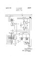
which the single figure is a diagrammatic view of the apparatus and circuits compris ing one embodiment of my invention.
Referring to the drawing, an induction regulator l is provided for regulating the voltage of a circuit comprising conductors 2, 3. A primary coil 4 of the regulator is connected in parallel circuit relation to, and a secondary coil 5 is connected in series circuit relation with, the conductors 2, 3 of the circuit to be regulated. An electric motor 6 is provided for changing the relative positions of the primary and secondary coils of the induction regulator. The motor 6 is actuated in accordance with the operation of circuit controlling relays 25 and 26, that are selectively energized by the. operation of a time delay relay 9, that is, in turn, controlled by a relay, or contact-making voltmeter 7, actuated in accordance with an electrical uantity, such as voltage, of the circuit eing regulated.
The relay, or contact-makin voltmeter 7,
comprises a lever 12, actuated y an electromagnet 10 and movably supported by the pivot 13. This lever carries movable contact members 14 and 15, which cooperate, respectively, with stationary contact members 16 and 17, to close circuits which energize the relay 9. The electromagnet 10 is provided with a coil that is energized from the transformer 11, in accordance with the voltage across the circuit conductors 2, 3. Engagement of contact members 14 and'16, or 15 and 17, closes acircuit through the primary winding of one of the two transformers 8 or 8, connecting it to conductors 35 and 36 of an auxiliary supply circuit, represented by conductors 35, 36 and 37. The energization of the one or the other of the transformers 8 or 8 cfiises one of the windings 19 or 18 and the winding 20 and 20 of the relay 9 to be energized and to efiect its operation in the one or in the other direction, and after an interval of time, to, operate the one or the I other of the relays 25 or 26. The transformers 8 and 8' permit the use of a voltage on the windings of relay 9 that is less than the voltage of the conductors 35, 36, 37. By varying the tap connections to those transformers the time element of the relay 9 may be adjusted.
The relay 9, which is shown as being of the induction type, comprises a magnetizable core structure, having an outer ring 50, of magnetic material, and a projection 51, extending centrally upwardly therefrom, together with two ( projections 52 and 53, extending downwar ly, from the upper part of the'magnetic structure, on either side of the vertical axis thereof. Windings 18 and 19 are provided on the upwardly extending projection 51, and the windings 20 and 20 are provided upon the projections 52 and 53, respectively. A movable disk 21, of copper, or other suitable 1 material, is rotatably mounted between the ends of the pole pieces, or projections of the magnetic circuit, and adapted to move in the one or in the other direction, according to the direction of the energization of the magnetic circuit of the relay, and to correspondingly actuate a coni tact member 22, that cooperates with the one or the other of two stationary contact members 23 and 24. The positions of these stationary contact members are adjustable, in order that the length of time required to effect an engagement'of contact member 22, with either of the stationary contact members 23 or 24 may be varied. The relay 9 is normally so biased that the contact member 22 is held out of engagement with the contact members 23 and 24 when the relay windings are deenergized.
Upon the energization of transformer 8, current flows from the secondary winding 54 thereof, through conducton 55, winding 18, conductor 56, windin s 20 and 20', and conductor 57 to the win 'ng 54, energizing the relay 9 to operate in one direction. Upon the energization of transformer 8, current flows from the secondary winding 58 thereof, through conductor 59, coil 19, conductor 56, windings 20 and 20, and conductor 57 to the winding 58. The relation of the coils 18 and 19 is such, that they produce flux in opposite directions, which combine with the fluxirom the coils 20 and 20 to produce opposite directions of rotation of the member 21.
The engagement of the contact member 22, with one of the stationary contact members 23 or 24, of the relay 9, causes an energizing circuit to be completed through the operating coils of one of the relays 25 and 26, thus actuating it to a circuit closing position. The relay 25, when operated, closes a circuit through the cooperating pairs of contact members 28,and 29, causing the motor 6 to operate in one direction. The relay 26, when operated, closes a circuit through the contact members 30, and the contact members 31, causing motor 6 to operate in the opposite direction. The motor 6 is illustrated asa three-phase motor, energized from a separate three-phase source of supply, the motor leads 32, 33 and 34 being connected to the alternating current source 35, 36 and 37 in a particular phase relation, in accordance with the operation of the relays 25 and 26.
The operation of the system is as follows:
If the voltage of the circuit 2, 3 decreases with respect to its desired value, the energization of electromagnetlO will decrease, and cause the core thereof to move downwardly, thus actuating the lever 12 to effect engagement of the contact members 14 and 16. This will complete a circuit through .the primary winding of the tap-changing transformer 8. This circuit leads from the conductor 36, of the alternating current power source, through conductor 38, lever 12, contact members l4 and 16, through the primary coil of the tap-changing transformer 8, through conductor 40, limit switch 44, and conductor 41, to conductor 35 of the alternating current power source.
When the primary coil of the tap-changing transformer 8 is energized, current flows from the secondary coil 54 of the transformer through the coils 18, 20 and 20 of the relay 1,
9, thus causing the element 21 and the contact member 22 to rotate. If the voltage variation continues for a predetermined time, thus maintaining the contact members 14 and 16 in engagement, the movable contact member .22 will engage the stationary contact member 23, thereb completing a circuit through the operating coil of the relay 25.
This circuit leads from the. conductor 36 of the alternating current power source,
through conductor 38, conductor 42, contact members 22 and 23, conductor 43, the operating coil of the relay 25, limit switch 44 and conductor 41, to conductor 35 of the alternating current power source.
The relay 25 now operates and effects engagement of the cooperating pairs of contact members 28 and 29, thus completing the circuit to the motor 6, and causing it to change the position of the winding 5' relative to winding 4, and secure the correction required to maintain the desired voltage on the circuit 2, 3.
If the voltage of the circuit 2, 3 increases above its desired value, the core of the electromagnet 10 will move upwardly, effecting engagement of the contact members 15, and
17 and completing a circuit through the primary winding of the tap-changing transformer 8. A current will then flow through the windings 19, 20 and 20, that are con- I nected in series circuit relation with the secondar winding 58, of the tap changing trans ormer 8. The movable disk 21 will then be actuated to rotate in a direction opposite to that described above, and, if continued'for a predetermined time, effect the engagement of the contact members 22 and 24. The engagement of the contact members 22 and 24 will complete a circuit through the operating coil of the relay 26, and actuate it to a circuit closing position. This operation of the relay 26 will efi'ect engagement of the cooperating pairs of contact members 30 and 31, thus completing a circuit through the motor 6, and causing it to operate in a direction to raise the voltage of the circuit 2, 3 to the desired value.
While I have described my system as applied to the control of an induction regulator, it is apparent that it may be used to control other forms of regulators, and it may be connected to be responsive to current changes, or to any other electrical quantity of the controlled circuit.
It will be evident, from the foregoing description, that the disclosed system for regulating an electrical quantity of a power circuit does not immediately correct for changes in the electrical quantity regulated, but makes this correction when the variation in the electrical quantity is maintained for a predetermined time.
Many modifications of the described embodiment of my invention within the spirit thereof, will occur to those skilled in the art, and, I do not wish to be limited other than by the scope of the appended claims.
v I claim as my invention 1. In a regulator system, an electric circuit, regulator means connected to said circuit for varying an electrical quantity thereof, electro-responsive means for operating said regulator means, a plurality of relays for controlling the energization of said electro-responsive means, contact-making means actuated in accordance with the voltage of said circuit for controlling the energization' of said relays, means controlled by said contactmaking means for introducing a time delay between the operation of said contact-making means and one of the said relays, and
means for adjusting the value of the time delay.
2. In a regulator system, an electric circuit, regulator means connected to said circuit for ,varying an electrical quantity thereof, and operating means therefor, means for controlling the operation of said operating means comprising a primary rela responsive to variations of the voltage 0 said circuit, a secondary relay controlled thereby, means for introducing a time delay of predetermined value, between the operation of the primar rela and the secondary rela and means or ad3usting the predetermine value of the time delay.
3. In a regulator system, an electric circuit, an induction regulator connected to said circuit for varying an electrical quantity thereof, an electric motor for operating said induction regulator, a secondary relay for for controlling the operation'of said electric motor, a primary relay actuated in accordance with variations in an electrical quantity of said circuit for controlling the operation of the secondary relay, means for delaying the operation of the secondary relay for a predetermined time after the response of the primary relay to variations in an electrical quantity of said electric circuit, and means for adjusting the value of the predetermined time.
4. In a regulator system, an electric circuit, an induction regulator connected to said circuit for varying an electrical quantity thereof, an electric motor for operating said induction regulator, av secondary relay for controlling the operation of said electric motor, a primary relay actuated in accordance with variations in an electrical quantity of said circuit, for controlling the operation of the secondary relay and comprising coopcrating contact members, an electric relay of the induction type for delaying the operation of the secondary relay after the operation of the primary relay.
5. In a regulator system, an electric circuit, an induction regulator connected to said circuit for varying an electrical quantity thereof, an electrical motor for operating said induction regulator, a secondary relay for controlling the operation of said electric motor, a primary relay actuated in ac- M site directions and means for adjusting the value'of the predetermined time delay.
In testimony whereof, I have hereunto subscribed my name this ith day of February,
EDWARD R. ,WOLFERT.
Priority Applications (2)
| Application Number | Priority Date | Filing Date | Title |
|---|---|---|---|
| US33790329 US1852551A (en) | 1929-02-06 | 1929-02-06 | Regulator system |
| DE1930579931D DE579931C (en) | 1929-02-06 | 1930-01-28 | Device for regulating the fluctuating voltage of an alternating current network |
Applications Claiming Priority (1)
| Application Number | Priority Date | Filing Date | Title |
|---|---|---|---|
| US33790329 US1852551A (en) | 1929-02-06 | 1929-02-06 | Regulator system |
Publications (1)
| Publication Number | Publication Date |
|---|---|
| US1852551A true US1852551A (en) | 1932-04-05 |
Family
ID=23322505
Family Applications (1)
| Application Number | Title | Priority Date | Filing Date |
|---|---|---|---|
| US33790329 Expired - Lifetime US1852551A (en) | 1929-02-06 | 1929-02-06 | Regulator system |
Country Status (2)
| Country | Link |
|---|---|
| US (1) | US1852551A (en) |
| DE (1) | DE579931C (en) |
-
1929
- 1929-02-06 US US33790329 patent/US1852551A/en not_active Expired - Lifetime
-
1930
- 1930-01-28 DE DE1930579931D patent/DE579931C/en not_active Expired
Also Published As
| Publication number | Publication date |
|---|---|
| DE579931C (en) | 1933-07-03 |
Similar Documents
| Publication | Publication Date | Title |
|---|---|---|
| US2254039A (en) | Voltage regulator relay system | |
| US2078667A (en) | Automatic control system for phase-advancing means | |
| US1852551A (en) | Regulator system | |
| US2680832A (en) | Voltage regulating means | |
| US2295355A (en) | Electrical apparatus | |
| US2079492A (en) | Electrical regulating system | |
| US2154020A (en) | Constant voltage system | |
| US2057458A (en) | Electric regulator | |
| US2216595A (en) | Time delay circuit | |
| US3536817A (en) | Electric furnace regulation system | |
| US2447634A (en) | Motor operated tap changer | |
| US1915050A (en) | Regulating system | |
| US2198736A (en) | Voltage regulating relay | |
| US2885628A (en) | Alternating current control system utilizing saturable reactor for regulation | |
| US2114890A (en) | Regulating apparatus | |
| US2292123A (en) | Regulator system | |
| US1234865A (en) | Electrical regulator. | |
| US2121601A (en) | Regulating apparatus | |
| US1234864A (en) | Electrical regulator. | |
| US2605456A (en) | Regulating system | |
| US2059885A (en) | System of electric distribution | |
| US2277652A (en) | Voltage regulator | |
| US2707767A (en) | Electrical regulating system | |
| US2259135A (en) | Stabilizing system | |
| US2068577A (en) | Compensating circuit |