US1852513A - Umbrella frame - Google Patents
Umbrella frame Download PDFInfo
- Publication number
- US1852513A US1852513A US319355A US31935528A US1852513A US 1852513 A US1852513 A US 1852513A US 319355 A US319355 A US 319355A US 31935528 A US31935528 A US 31935528A US 1852513 A US1852513 A US 1852513A
- Authority
- US
- United States
- Prior art keywords
- ribs
- bearings
- portions
- sleeve
- pole
- Prior art date
- Legal status (The legal status is an assumption and is not a legal conclusion. Google has not performed a legal analysis and makes no representation as to the accuracy of the status listed.)
- Expired - Lifetime
Links
- 239000004744 fabric Substances 0.000 description 8
- 239000002184 metal Substances 0.000 description 2
- 241001417524 Pomacanthidae Species 0.000 description 1
- 238000010276 construction Methods 0.000 description 1
- 238000006073 displacement reaction Methods 0.000 description 1
- 239000000463 material Substances 0.000 description 1
- 239000002023 wood Substances 0.000 description 1
Images
Classifications
-
- A—HUMAN NECESSITIES
- A45—HAND OR TRAVELLING ARTICLES
- A45B—WALKING STICKS; UMBRELLAS; LADIES' OR LIKE FANS
- A45B25/00—Details of umbrellas
- A45B25/06—Umbrella runners
-
- A—HUMAN NECESSITIES
- A45—HAND OR TRAVELLING ARTICLES
- A45B—WALKING STICKS; UMBRELLAS; LADIES' OR LIKE FANS
- A45B25/00—Details of umbrellas
- A45B25/10—Umbrella crowns
Definitions
- the main object is to provide a durable, strong and rigid structure which will withstand ordinary strains of usage as well as wind strains.
- Another object is to provide a structure of the character described in which a top notch or ring is stationa-rlly held near the upper end of the center pole and is formed of sheet metal with substantially elongated bearings for receiving the inner ends of the ribs which are transversely bent so as to pivot in said bearings.
- An object also is to provide an elongated movable sleeve 011 the center pole having bearings similar to those on the ferrule for receiving and pivotally supporting the inner ends of the rib braces.
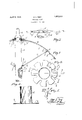
- Fig. 1 is a fragmentary enlarged sectional elevation oi an umbrella of the beach type embodying my improvements.
- Fig. 3 is a top plan view oi? the movable sleeve with the brace bearing portions ex tended tlatwise prior to forming the same int-o bearings.
- i at is a sectional elevation of the same on line 4-4: of Fig. 3.
- Fig. is a fragmentary plan view of the movable sleeve showing the bent ends of the braces mounted in the sleeve bearings and held therein.
- My improved structure embodies the usual central pole A, preferably formed of wood, with the circular fabric covering B which is adapted to be supported at a plurality of points on a series of radially disposed ribs C, C etc. Said ribs are individually braced by means of rods D, D etc.
- the upper end of the pole A carries a fixed top notch E suitably attached to the pole and arranged to pivotally support the inner ends C, C etc. of the ribs C, C etc.
- a ferrule F is attached to the end of the pole for holding the fabric B in contact with the notch E, and a pin G may be employed on the upper end of the pole, as shown, tho this is not material.
- the notch E has a cylindrical portion 0 tightly fitting the periphery of the pole A and attached thereto by means of nails or screws, as at e.
- a plurality of radially and outwardly extended portions f, f etc. are formed on the notch E and are bent downwardly and upwardly to form elongated bearings f, f etc. Said bearings are thus tangentially disposed relative to a circle touching the axes of the hinge portions 0, C etc. of the ribs C, C etc.
- Said hinge portions C of the ribs are bent at right angles to the ribs and are of sufficient length and the ribs are of suflicient size and strength so as to substantially prevent any lateral movement of the ribs or displacement of the ribs from their operating positions under the fabric B. It is customary to attach the ribs at certain points to the fabric B by means of ties, as at b, or otherwise.
- Substantially below the top notch E 1 provide an elongated sleeve H which has its upper end formed similarly to the lower portion of the notch E in that it has a plurality of outwardly extended radially disposed portions it, 71. etc. formed at right angles to the body of the sleeve and bent into loops as at h, to form elongated bearings for pivotally receiving the right angularly bent hinge portions (Z of the braces D.
- the sleeve H is adapted to be locked when the fabric B is extended for use by the usual spring latch I. which engages the lower edge :5 of the sleeve I
- the outer ends of the braces D carry hinge members J which pivotally connect at points cl with fittings K frictionally held in positions on the ribs C.
- Suitable fittings, as at L may be attached to the ends of the ribs C and to the edge of the fabric B for connecting the fabric and ribs.
- both the topnotch E and the "sleeve are stormed in the same manner as t0 the form and position of the bearing portions 7 and h respectively.
- the ribs C and the braces Dare so formed at their inner ends that the right angular portions 0 and cl respectively there'- of areeXtended for substantially equal dis- ;tances on opposite sides of the axes of the "bodies of such members, as shown in broken lines *ofFig. 3.
- the portions C and il of the ribs and braces are bent at right angles to 'and are connected with the bodies of SH i ClIHBHllOGISby diametrically formed por- .tions .D.
- the portions fand 71, of the top notch E and the sleeve H are undercut at their roots, as at M, M etc.
Description
April 5, 1932. E FREY 1,852,513
UMBRELLA FRAME Filed Nov. 14, 1928 l/IIIiIII/illl- ATTORNEY Patented Apr. 5, 1931'.
UNl'i ED STATES PATENT OFFICE ELIVIEIt E. FREY, OF LOS ANGELES, CALIFORNIA, ASSIGNOR TO EDWARD F. LEONARD AND JOHN P. MEEHAN, BOTH 0F L03 ANGELES, CALIFORNIA UMBRELLA FRAME Application filed November 14, 1928. Serial No. 319,355.
known as beach umbrellas.
The main object is to provide a durable, strong and rigid structure which will withstand ordinary strains of usage as well as wind strains.
To this end it is a subsidiary object to provide means for pivotally attaching the upper ends of the ribs to the center pole and the inner ends of the rib braces to the center pole in such a manner that the ribs will be at all times substantially supported in radial planes and tree from wabbling and unsteadiuses, which usually attendant upon the ribs of other well known types of umbrellas.
Another object is to provide a structure of the character described in which a top notch or ring is stationa-rlly held near the upper end of the center pole and is formed of sheet metal with substantially elongated bearings for receiving the inner ends of the ribs which are transversely bent so as to pivot in said bearings.
An object also is to provide an elongated movable sleeve 011 the center pole having bearings similar to those on the ferrule for receiving and pivotally supporting the inner ends of the rib braces.
Other objects may appear as the description progresses.
in the accompanying drawings,
Fig. 1 is a fragmentary enlarged sectional elevation oi an umbrella of the beach type embodying my improvements.
2 is a fragmentary elevation ot the n'iovable sleeve and rib braces pivoted thereto.
Fig. 3 is a top plan view oi? the movable sleeve with the brace bearing portions ex tended tlatwise prior to forming the same int-o bearings.
i at is a sectional elevation of the same on line 4-4: of Fig. 3.
Fig. is a fragmentary plan view of the movable sleeve showing the bent ends of the braces mounted in the sleeve bearings and held therein.
My improved structure embodies the usual central pole A, preferably formed of wood, with the circular fabric covering B which is adapted to be supported at a plurality of points on a series of radially disposed ribs C, C etc. Said ribs are individually braced by means of rods D, D etc. The upper end of the pole A carries a fixed top notch E suitably attached to the pole and arranged to pivotally support the inner ends C, C etc. of the ribs C, C etc. Usually a ferrule F is attached to the end of the pole for holding the fabric B in contact with the notch E, and a pin G may be employed on the upper end of the pole, as shown, tho this is not material.
The notch E has a cylindrical portion 0 tightly fitting the periphery of the pole A and attached thereto by means of nails or screws, as at e. A plurality of radially and outwardly extended portions f, f etc. are formed on the notch E and are bent downwardly and upwardly to form elongated bearings f, f etc. Said bearings are thus tangentially disposed relative to a circle touching the axes of the hinge portions 0, C etc. of the ribs C, C etc. Said hinge portions C of the ribs are bent at right angles to the ribs and are of sufficient length and the ribs are of suflicient size and strength so as to substantially prevent any lateral movement of the ribs or displacement of the ribs from their operating positions under the fabric B. It is customary to attach the ribs at certain points to the fabric B by means of ties, as at b, or otherwise.
Substantially below the top notch E 1 provide an elongated sleeve H which has its upper end formed similarly to the lower portion of the notch E in that it has a plurality of outwardly extended radially disposed portions it, 71. etc. formed at right angles to the body of the sleeve and bent into loops as at h, to form elongated bearings for pivotally receiving the right angularly bent hinge portions (Z of the braces D.
The sleeve H is adapted to be locked when the fabric B is extended for use by the usual spring latch I. which engages the lower edge :5 of the sleeve I The outer ends of the braces D carry hinge members J which pivotally connect at points cl with fittings K frictionally held in positions on the ribs C. Thus, as the sleeve H is moved upwardly and downwardly on the pole A the ribs C and the fabric B will be extended and contracted by reason of the pivotal connections C, d and d. Suitable fittings, as at L, may be attached to the ends of the ribs C and to the edge of the fabric B for connecting the fabric and ribs. As shown in Fig. 3', both the topnotch E and the "sleeve are stormed in the same manner as t0 the form and position of the bearing portions 7 and h respectively.
Preferably the ribs C and the braces Dare so formed at their inner ends that the right angular portions 0 and cl respectively there'- of areeXtended for substantially equal dis- ;tances on opposite sides of the axes of the "bodies of such members, as shown in broken lines *ofFig. 3. To this end the portions C and il of the ribs and braces are bent at right angles to 'and are connected With the bodies of SH i ClIHBHllOGISby diametrically formed por- .tions .D. Also the portions fand 71, of the top notch E and the sleeve H are undercut at their roots, as at M, M etc. to receive the joints d between the portionsd and D and the portions C and Dso that when the -portions fand-h are formed into the loopsf and h" respectively the ribs C and the braces D Will be held in their vrespective bearings against (removal vby the engagement of the end extensions N of the loops f and "72," with said joints (.see Figs. 2 and 3).
The advantages of the type of construction shown and described herein will readily appear to :those'skilled in the art of umbrella manufacturing-andsuch astructure is-equally adapted for (use in large umbrellas.
that I claim is:
In an umbrella frame, a supporting fixture formed of a piece of sheet metal comprisinga cylindrical skirt adapted to engage the periphery oztan umbrella standard, and a flange formed Witha plurality ="0f radially extending ,portions with bulges at one side thereof .bentrinto loops extending tran sversely thereof in the .formofhinge bearings, and ro ds bentitransversely at their "inner endsand turnably fitted in said loops, the bulges of said hinge bearings engaging the bent portions of the rods respectively inadj acent bearings to prevent Withdrawal of the bent ends of said rods from said bearings.
ELMER E. FREY.
Priority Applications (1)
| Application Number | Priority Date | Filing Date | Title |
|---|---|---|---|
| US319355A US1852513A (en) | 1928-11-14 | 1928-11-14 | Umbrella frame |
Applications Claiming Priority (1)
| Application Number | Priority Date | Filing Date | Title |
|---|---|---|---|
| US319355A US1852513A (en) | 1928-11-14 | 1928-11-14 | Umbrella frame |
Publications (1)
| Publication Number | Publication Date |
|---|---|
| US1852513A true US1852513A (en) | 1932-04-05 |
Family
ID=23241904
Family Applications (1)
| Application Number | Title | Priority Date | Filing Date |
|---|---|---|---|
| US319355A Expired - Lifetime US1852513A (en) | 1928-11-14 | 1928-11-14 | Umbrella frame |
Country Status (1)
| Country | Link |
|---|---|
| US (1) | US1852513A (en) |
Cited By (7)
| Publication number | Priority date | Publication date | Assignee | Title |
|---|---|---|---|---|
| FR2556938A1 (en) * | 1983-12-23 | 1985-06-28 | Kortenbach & Rauh Kg | UMBRELLA |
| USD814782S1 (en) * | 2013-09-19 | 2018-04-10 | Oliver Joen-An Ma | Umbrella runner |
| US20180153269A1 (en) * | 2016-12-07 | 2018-06-07 | ZHUN-AN Ma | Umbrella hub assembly |
| US10631603B2 (en) | 2015-09-14 | 2020-04-28 | Oliver Joen-An Ma | Quick assembly methods and components for shade structures |
| US10631604B2 (en) | 2012-04-19 | 2020-04-28 | ZHUN-AN Ma | Umbrella quick frame assembly systems and methods |
| US10631605B2 (en) | 2015-09-14 | 2020-04-28 | Oliver Joen-An Ma | Umbrella hub |
| US10874182B2 (en) | 2016-10-25 | 2020-12-29 | ZHUN-AN Ma | Umbrella rib connector assemblies and methods |
-
1928
- 1928-11-14 US US319355A patent/US1852513A/en not_active Expired - Lifetime
Cited By (10)
| Publication number | Priority date | Publication date | Assignee | Title |
|---|---|---|---|---|
| FR2556938A1 (en) * | 1983-12-23 | 1985-06-28 | Kortenbach & Rauh Kg | UMBRELLA |
| US10631604B2 (en) | 2012-04-19 | 2020-04-28 | ZHUN-AN Ma | Umbrella quick frame assembly systems and methods |
| USD814782S1 (en) * | 2013-09-19 | 2018-04-10 | Oliver Joen-An Ma | Umbrella runner |
| US10631603B2 (en) | 2015-09-14 | 2020-04-28 | Oliver Joen-An Ma | Quick assembly methods and components for shade structures |
| US10631605B2 (en) | 2015-09-14 | 2020-04-28 | Oliver Joen-An Ma | Umbrella hub |
| US11206904B2 (en) | 2015-09-14 | 2021-12-28 | Oliver Joen-An Ma | Quick assembly methods and components for shade structures |
| US10874182B2 (en) | 2016-10-25 | 2020-12-29 | ZHUN-AN Ma | Umbrella rib connector assemblies and methods |
| US20180153269A1 (en) * | 2016-12-07 | 2018-06-07 | ZHUN-AN Ma | Umbrella hub assembly |
| US10736390B2 (en) * | 2016-12-07 | 2020-08-11 | ZHUN-AN Ma | Umbrella hub assembly |
| US11206905B2 (en) | 2016-12-07 | 2021-12-28 | ZHUN-AN Ma | Umbrella hub assembly |
Similar Documents
| Publication | Publication Date | Title |
|---|---|---|
| TWI520695B (en) | A folding chair with a locking structure | |
| JP4417436B2 (en) | Folding umbrella with reinforced rib structure | |
| US6354316B1 (en) | Skeleton for umbrella tent | |
| US1852513A (en) | Umbrella frame | |
| US10138652B2 (en) | Foldable tent rack | |
| US10016033B2 (en) | Adjustable canopy umbrella with auditory pin locking and centering system | |
| US3069021A (en) | Garment drying apparatus | |
| US1839309A (en) | Collapsible umbrella | |
| JPS6134803B2 (en) | ||
| US2296666A (en) | Folding or collapsible umbrella | |
| US4586524A (en) | Clothes hanger handle for umbrellas | |
| US2775977A (en) | Collapsible umbrella | |
| US2296043A (en) | Supporting stand | |
| US1349281A (en) | Umbrella | |
| US1534820A (en) | Umbrella | |
| US1843961A (en) | Folding umbrella | |
| US3119402A (en) | Tent assembly | |
| US2146517A (en) | Portable shelter | |
| US1748068A (en) | Garment hanger | |
| US9713367B2 (en) | Umbrella shaft assembly | |
| US3163297A (en) | Collapsible clothes dryer | |
| US2731973A (en) | Tiltable umbrella | |
| US2492457A (en) | Collapsible umbrella | |
| US1969260A (en) | Supporting fabrication for tents | |
| US3160166A (en) | Contractible umbrella |