US1852484A - Apparatus for recording audible and visual effects of collisions - Google Patents
Apparatus for recording audible and visual effects of collisions Download PDFInfo
- Publication number
- US1852484A US1852484A US401005A US40100529A US1852484A US 1852484 A US1852484 A US 1852484A US 401005 A US401005 A US 401005A US 40100529 A US40100529 A US 40100529A US 1852484 A US1852484 A US 1852484A
- Authority
- US
- United States
- Prior art keywords
- pawl
- camera
- switch
- motor
- locomotive
- Prior art date
- Legal status (The legal status is an assumption and is not a legal conclusion. Google has not performed a legal analysis and makes no representation as to the accuracy of the status listed.)
- Expired - Lifetime
Links
Images
Classifications
-
- B—PERFORMING OPERATIONS; TRANSPORTING
- B61—RAILWAYS
- B61L—GUIDING RAILWAY TRAFFIC; ENSURING THE SAFETY OF RAILWAY TRAFFIC
- B61L1/00—Devices along the route controlled by interaction with the vehicle or vehicle train, e.g. pedals
- B61L1/20—Safety arrangements for preventing or indicating malfunction of the device, e.g. by leakage current, by lightning
Definitions
- the invention has for a further object to provide an apparatus of the character stated wherein the combined motion picture camera and sound recorder shall be so mounted upon the locomotive or the like as to protect the mechanism thereof from injury by and as a result of the vibrating of the locomotive.
- the invention has for a further object to provide an apparatus of the character stated which shall include a motor for the combined motion picture camera and sound recorder and adapted to beset in operation by either the engineer or fireman ofthe locomotive.
- the invention has l/for a further object to I provide an apparatus of the character stated which shall include a shieldfor.
- the invention has for a stil-lfurther object to providel an apparatus d the character stated 'which shall include electricallyopei-,y ated means for controlling the motor and coni trol switches for said means located one at the engineers side and the other aty the iremans side of the locomotive cab so as to perf mit the motor to be set in operation by either the engineer orfireman.
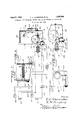
- Figure 1 is a view partly elevational and partly diagrammatic of the apparatus with the motor control means in active position;
- Figure 2 is a view somewhat similar to Figure l with the motor control means in inactive position; Y
- Figure 3 is a sectional view illustrating the 60 motor of the apparatus.
- Figure 4 is a front view illustrating the lens shield.
- the apparatus comprises a combined motion picture camera and sound recorder 1 which may be any well known or appropriate construction and is shown as embodying a casing 2, a lens 3, a film 4 and film spools 5 and 6.
- the lens 3 is of wide vision type, and the film 4 may be and preferably is of the type in which may be formed sound wave recording grooves.
- Any well known means, such as a diaphragm 7 anda stylus 8, may be employed for forming sound -Wave recordin grooves in the film 4.
- the film 4 is unwoun from the spool 5 on to the spool 6 during the operation of the camera and recorder 1, and during the movement thereof', the pictures recorded and the sound wave recording proof is form'ed.
- a spring motor 9 is employed for the purpose of operating the camera and the recorder 1. It may be any well known or appropriate construction, and is shown as embodying a shaft 10, a spring 11 coiled about the shaft and secured at one end thereto and at its other end to the casing 2, and ⁇ gears 12 establishing a driving connection between the Sliaftand the spool 6. Bearings 13 are se ⁇ ycured 'to .onewall of 'the casing 2. A notched di-sc 14a-fixed1'touthe shaft l() and a pawl l5 pivoted .at itslowerend, ⁇ as at 16, to the casing 2 and having itsupper or free end ⁇ engaging in the notchl'?
- the pawl 15 ⁇ is normally held in engagement in the notch 17 by a spring 18, and it is adapted to be retracted o1' withdrawn from the notch through the medium of an electromagnet 19.
- the electromagnet 19 ' is included in a circuit which-com rises awbattery 20, switches 21 and 22, a con uctor'23v extending from one pole of the battery to one terminal of the winding electromagnet, and conductor 24 extending from the other terminal of the electromagnet to one of the contacts of the switch 21, and a conductor 25.,extending from the other pole of the battery with the other con' tact of the switch.
- the switch 22 has its contact connected to the conductors 24 and 25 by conductors 26.
- the switches 21 and 22 are preferably of the push button type, and one will be arranged within the locomotive cab at the engineers side and the other in the cab at the iremans side whereby to permit either the engineer or fireman to close the circuit of the electromafgnet 19 when it appears to either that there is likelihood of a collision between the locomotive and an alitomobile approaching the roadway.
- the closing V ⁇ of this circuitresults in the retraction of the pawl 15, and the retraction of the pawl permits the motor to operate the camera and recorder 1 which will be preferably mounted on the front of the locomotive below the headlight.
- the location of the camera andrecorder 1 and the wide range lens 3 will per# mit thephotographing of a tracty of ground greater in width than and including the railway in advance of the locomotive, together with the grade-crossing on both sides of the railway.
- The, sounding of the whistle of the locomotive, together with other sounds incident to a collision, should one take place, will lbe recorded on the film by the diaphragm 7 and stylus 8.
- the pawl 15 is retracted by the electromagnet 19 against the tension of the spring 18, and it is held retracted b the disc 14 during such time as it requires t e disc to make one complete rotation. In view thereof, itis only necessary for the engineer or fireman to press and immediately thereafter release his switch.
- the size of the disc 14 controls the operating period of the motor 9 and cameraland recorder 1, it will be understood that these parts may be caused tooperate for any desired or required period of these lamps will be mounted on the engineers side and the other onthe iremans side of the locomotive.
- rI he lamps 27 and 28 are under the control of a switch 29 which is automatically closed by the retractionof the pawl 15 and automatically opened by the projection of the pawl into'the disc notch 17.
- the switch 29 -includes a fixed contact 30 secured to and insulated from the casingv 2 and a movable spring of the contact 31 fixed to and insulated from the pawl, 15.
- the casing 2 is provided with a jacket 38 which is adapted to protect the parts of the camera and recorder 1 from shocks and jars as the result of the vibration of the locomotive. -Y
- the lens 3 is provided with a shield 39 which is pivotally mounted, as at 40, for movement into and out of lens protecting position.
- Any' suitable means may be provided for normally holding the shield 39 in lens protecting position and for releasing it for movement into lens uncovering position immediately for the operation of the camera and recorder 1.
- this means may consist of a spring 4l serving to normally hold the shield 39 in lens protecting position, and a cable 42 connected to thel shield and to the pawl 15 so as to permit the retraction of the pawl to move the shield into lens uncovering. position.
- the shield 39 will be moved into this position against the tension of the spring 41, and will be"returned to its ⁇ normal osition by the spring on the projection 0f t e pawl 15.
- An apparatus of the character set forth comprising a combined motion picture camera and sound recorder, a spring motor having a shaft operatively connected to the camera and recorder, a notched disc xed to the shaft, a pivoted pawl engaging in the notch of the disc to hold the motor against operation, a spring holding the pawl in the notch of the disc', an electromagr.
- et adapted when energized to retract the awl, an electric circuit including the electromagnet, switches in said circuit remote from the camera, and recorder, telltale'lamps located near the switches, an electric circuit including the'lamps, and a switch in said second circuit lnear the camera and recorder and under the control of the pawl and adapted to be held open by the pawl when the latter is in normal position and closed by the pawl when the latter is in retracted position.
- An apparatus of the character set forth comprising a motion picture camera, a motor having a shaft operatively connected to the camera, a notched disk fixed to the shaft, a
- vpivoted pawl engaging in the notch of the disk to hold the motor against operation, a spring holding the pawl in the notch of the disk, an electromagnet adapted when ener' gized to retract the pawl, an electric circuit including the electromagnet, a switch in said circuit remote from the camera, a telltale lamp located near the switch, an electric circuit including the lamp, and a switch in said circuit near the camera and under the control of the pawl and adapted to be held open by the pawl when the atter is in engagement with the notch in the disk and closed by thepawl when the latter is retracted from engagement with the disk.
- An apparatus of the character set forth comprising a motion picture camera, a motor 'having a shaft operatively connected to the camera, a notched vdisk fixed to the shaft, a pivoted pawl engaging in the notch of the disk to hold the motor against operation, a
- an electromagnet adapted when energized to retract the pawl, an electric circuit including'the electromagnet, a switch in said circuit remote from the camera, a telltale lamp located near the switch, an electric circuit including the lamp, a switch in said circuit near the camera and under the control of the pawl and adapted to be held open by
Description
AApril 5, l932- F. c. sHuMAKl-:R ETAL 1,852,484
APPARATUS FOR RECORDING AUDIBLE ND VISUAL EFFECTS OF COLLISIONS Filed OCT.. 19, 1929 l Rf wf@ Q0 f L? nk i Patented Apr. 5, 1932 UNITED STATES PAT-ENT OFFICE FREDERIC C. SHUMAKER AD EMERSON W. GREGORY, OF SANGEB, CALIFORNIA 1- APPARATUS FOR RECORDING AUDIBLE ANDY VISUAL EFFECTS 0F COLLISIONS Application led October 19, 1929.j Serial No. 401,005.
which]y shall include a combined motion picture camera and sound recorder having a wide vision lens and adapted to be mounted upon a locomotive or the like in such position as to permit the photographing, in advance of the locomotive, of a tract of groundl greater in width than and including the railway and to permit the recording of the sounding of the locomotive whistle and other audible effects of a collision'. I
The invention has for a further object to provide an apparatus of the character stated wherein the combined motion picture camera and sound recorder shall be so mounted upon the locomotive or the like as to protect the mechanism thereof from injury by and as a result of the vibrating of the locomotive.
The invention has for a further object to provide an apparatus of the character stated which shall includea motor for the combined motion picture camera and sound recorder and adapted to beset in operation by either the engineer or fireman ofthe locomotive.
The invention has l/for a further object to I provide an apparatus of the character stated which shall include a shieldfor. the lens'nor-v mally occupying a position Aacross the lensand adapted to be moved into a position V beyond the lens by andas the result of the operation of the motor. A,
The invention has for a stil-lfurther object to providel an apparatus d the character stated 'which shall include electricallyopei-,y ated means for controlling the motor and coni trol switches for said means located one at the engineers side and the other aty the iremans side of the locomotive cab so as to perf mit the motor to be set in operation by either the engineer orfireman.
The invention is hereinafter more fully described and claimed, and illustrated in the accompanying drawings, wherein Figure 1 is a view partly elevational and partly diagrammatic of the apparatus with the motor control means in active position;
Figure 2 is a view somewhat similar to Figure l with the motor control means in inactive position; Y
Figure 3 is a sectional view illustrating the 60 motor of the apparatus, and
Figure 4 is a front view illustrating the lens shield.
The apparatus comprises a combined motion picture camera and sound recorder 1 which may be any well known or appropriate construction and is shown as embodying a casing 2, a lens 3, a film 4 and film spools 5 and 6. The lens 3 is of wide vision type, and the film 4 may be and preferably is of the type in which may be formed sound wave recording grooves. Any well known means, such as a diaphragm 7 anda stylus 8, may be employed for forming sound -Wave recordin grooves in the film 4. The film 4 is unwoun from the spool 5 on to the spool 6 during the operation of the camera and recorder 1, and during the movement thereof', the pictures recorded and the sound wave recording proof is form'ed.
A spring motor 9 is employed for the purpose of operating the camera and the recorder 1. It may be any well known or appropriate construction, and is shown as embodying a shaft 10, a spring 11 coiled about the shaft and secured at one end thereto and at its other end to the casing 2, and` gears 12 establishing a driving connection between the Sliaftand the spool 6. Bearings 13 are se` ycured 'to .onewall of 'the casing 2. A notched di-sc 14a-fixed1'touthe shaft l() and a pawl l5 pivoted .at itslowerend,`as at 16, to the casing 2 and having itsupper or free end` engaging in the notchl'? of 'the disc, constitute means for 'releasably holding themotor against op eration. The pawl 15 `is normally held in engagement in the notch 17 by a spring 18, and it is adapted to be retracted o1' withdrawn from the notch through the medium of an electromagnet 19.
aoc
The electromagnet 19 'is included in a circuit which-com rises awbattery 20, switches 21 and 22, a con uctor'23v extending from one pole of the battery to one terminal of the winding electromagnet, and conductor 24 extending from the other terminal of the electromagnet to one of the contacts of the switch 21, and a conductor 25.,extending from the other pole of the battery with the other con' tact of the switch. The switch 22 has its contact connected to the conductors 24 and 25 by conductors 26. The switches 21 and 22 are preferably of the push button type, and one will be arranged within the locomotive cab at the engineers side and the other in the cab at the iremans side whereby to permit either the engineer or fireman to close the circuit of the electromafgnet 19 when it appears to either that there is likelihood of a collision between the locomotive and an alitomobile approaching the roadway. The closing V`of this circuitresults in the retraction of the pawl 15, and the retraction of the pawl permits the motor to operate the camera and recorder 1 which will be preferably mounted on the front of the locomotive below the headlight. The location of the camera andrecorder 1 and the wide range lens 3 will per# mit thephotographing of a tracty of ground greater in width than and including the railway in advance of the locomotive, together with the grade-crossing on both sides of the railway. The, sounding of the whistle of the locomotive, together with other sounds incident to a collision, should one take place, will lbe recorded on the film by the diaphragm 7 and stylus 8.
The pawl 15 is retracted by the electromagnet 19 against the tension of the spring 18, and it is held retracted b the disc 14 during such time as it requires t e disc to make one complete rotation. In view thereof, itis only necessary for the engineer or fireman to press and immediately thereafter release his switch. On the retraction of the pawl 15 as the result of the closing of one kof the switches 21 and 22, the disc 14 rotates in the direction indicated by the arrows'of Figures 1 and 2, and when the switch is released,the pawl is moved'into and held in contact with the periphery ofthe disc by the spring 18.- Whenthe disc 14 completes its rotation, the pawl 15 is moved into the notch 17 by the spring 18, with the result that the operation of the motor"9 and the camera and recorder 1 is stopped. As the size of the disc 14 controls the operating period of the motor 9 and cameraland recorder 1, it will be understood that these parts may be caused tooperate for any desired or required period of these lamps will be mounted on the engineers side and the other onthe iremans side of the locomotive. rI he lamps 27 and 28 are under the control of a switch 29 which is automatically closed by the retractionof the pawl 15 and automatically opened by the projection of the pawl into'the disc notch 17. The switch 29-includes a fixed contact 30 secured to and insulated from the casingv 2 and a movable spring of the contact 31 fixed to and insulated from the pawl, 15.
Current for the lamps 27 and 28 is provided by a battery 32, one pole of the battery being connected to the contact 30 by a conductor 33 and the otherI pole being connected to the lamps 27 and 28 by conductors 34 and 35. The Contact 31 is connected to the lamps 27 and, 28 and conductors 36 and 37. It will be seen that when either of the switches 21 and 22 is closed, the resulting retract-ion of the pawl 15 will close the switch 29, and that i the closing of the switch will result in the lighting of both the lamps 27 and 28. After the disc 14 has made one complete rotation, the switch 29 will be opened by the projection of the pawl 15 into the notch 17 by the spring 18.
The casing 2 is provided with a jacket 38 which is adapted to protect the parts of the camera and recorder 1 from shocks and jars as the result of the vibration of the locomotive. -Y
i The lens 3 is provided with a shield 39 which is pivotally mounted, as at 40, for movement into and out of lens protecting position. Any' suitable means may be provided for normally holding the shield 39 in lens protecting position and for releasing it for movement into lens uncovering position immediately for the operation of the camera and recorder 1. I-f desired, this means may consist of a spring 4l serving to normally hold the shield 39 in lens protecting position, and a cable 42 connected to thel shield and to the pawl 15 so as to permit the retraction of the pawl to move the shield into lens uncovering. position. The shield 39 will be moved into this position against the tension of the spring 41, and will be"returned to its` normal osition by the spring on the projection 0f t e pawl 15.
From the foregoing description, taken in connection with the accompanying drawings, it w1ll be apparent that we have .provided .19 andswitch 29, .and that the conductorsand.
lis
recense cahle 42 may he mounted in flexible metal sheets.
While we have described the principle of our invention, together with the structure which we now consider the preferred embodiment thereof, it is to he understood that the structure shown is merely illustrative and that such changes may he made, when desired, as fall within the scope of the inven-4 tion as claimed.
We claim l. An apparatus of the character set forth, comprising a combined motion picture camera and sound recorder, a spring motor having a shaft operatively connected to the camera and recorder, a notched disc xed to the shaft, a pivoted pawl engaging in the notch of the disc to hold the motor against operation, a spring holding the pawl in the notch of the disc', an electromagr. et adapted when energized to retract the awl, an electric circuit including the electromagnet, switches in said circuit remote from the camera, and recorder, telltale'lamps located near the switches, an electric circuit including the'lamps, and a switch in said second circuit lnear the camera and recorder and under the control of the pawl and adapted to be held open by the pawl when the latter is in normal position and closed by the pawl when the latter is in retracted position.
2. An apparatus of the character set forth, comprising a motion picture camera, a motor having a shaft operatively connected to the camera, a notched disk fixed to the shaft, a
vpivoted pawl engaging in the notch of the disk to hold the motor against operation, a spring holding the pawl in the notch of the disk, an electromagnet adapted when ener' gized to retract the pawl, an electric circuit including the electromagnet, a switch in said circuit remote from the camera, a telltale lamp located near the switch, an electric circuit including the lamp, and a switch in said circuit near the camera and under the control of the pawl and adapted to be held open by the pawl when the atter is in engagement with the notch in the disk and closed by thepawl when the latter is retracted from engagement with the disk.
3. An apparatus of the character set forth, comprising a motion picture camera, a motor 'having a shaft operatively connected to the camera, a notched vdisk fixed to the shaft, a pivoted pawl engaging in the notch of the disk to hold the motor against operation, a
spring holding rthe pawl in the notch of thev disk, an electromagnet adapted when energized to retract the pawl, an electric circuit including'the electromagnet, a switch in said circuit remote from the camera, a telltale lamp located near the switch, an electric circuit including the lamp, a switch in said circuit near the camera and under the control of the pawl and adapted to be held open by
Priority Applications (1)
| Application Number | Priority Date | Filing Date | Title |
|---|---|---|---|
| US401005A US1852484A (en) | 1929-10-19 | 1929-10-19 | Apparatus for recording audible and visual effects of collisions |
Applications Claiming Priority (1)
| Application Number | Priority Date | Filing Date | Title |
|---|---|---|---|
| US401005A US1852484A (en) | 1929-10-19 | 1929-10-19 | Apparatus for recording audible and visual effects of collisions |
Publications (1)
| Publication Number | Publication Date |
|---|---|
| US1852484A true US1852484A (en) | 1932-04-05 |
Family
ID=23585872
Family Applications (1)
| Application Number | Title | Priority Date | Filing Date |
|---|---|---|---|
| US401005A Expired - Lifetime US1852484A (en) | 1929-10-19 | 1929-10-19 | Apparatus for recording audible and visual effects of collisions |
Country Status (1)
| Country | Link |
|---|---|
| US (1) | US1852484A (en) |
Cited By (1)
| Publication number | Priority date | Publication date | Assignee | Title |
|---|---|---|---|---|
| US3081678A (en) * | 1960-01-11 | 1963-03-19 | Steineck Rudolf | Photographic camera |
-
1929
- 1929-10-19 US US401005A patent/US1852484A/en not_active Expired - Lifetime
Cited By (1)
| Publication number | Priority date | Publication date | Assignee | Title |
|---|---|---|---|---|
| US3081678A (en) * | 1960-01-11 | 1963-03-19 | Steineck Rudolf | Photographic camera |
Similar Documents
| Publication | Publication Date | Title |
|---|---|---|
| US1852484A (en) | Apparatus for recording audible and visual effects of collisions | |
| US2952740A (en) | Telephone attachment | |
| US1654943A (en) | Direction signal for vehicles | |
| US2045045A (en) | Headlight blinker for daylight signals | |
| US3076877A (en) | Magnetically controlled switch | |
| US1004059A (en) | Electric brake for graphophones. | |
| US1803241A (en) | Film-change-over signaling bell | |
| KR850004842A (en) | Automatic recording prevention mechanism of tape cassette | |
| US1059007A (en) | Electrical burglar-alarm. | |
| US1203420A (en) | Alarm-signal. | |
| US1828569A (en) | Film stopping apparatus | |
| US956727A (en) | Sound-reproducing machine and record therefor. | |
| US1555497A (en) | Direction indicator for vehicles | |
| US1799154A (en) | Motion-picture-projection apparatus | |
| US1772422A (en) | Bank-vault alarm system | |
| US1001830A (en) | Phonographic automobile-alarm. | |
| US1047110A (en) | Street-car signal. | |
| US307517A (en) | Eugene w | |
| US1223255A (en) | Electrical protective system. | |
| US792875A (en) | Block-signaling mechanism. | |
| US821629A (en) | Automatic cut-off for sound-reproducing machines. | |
| US1395017A (en) | Stop mechanism for phonographs | |
| US1549234A (en) | Winding device for spring motors | |
| US1251320A (en) | Telegraph circuit-closing and signaling system. | |
| US1006193A (en) | Electric switch. |