US1852404A - Portable fireplace - Google Patents
Portable fireplace Download PDFInfo
- Publication number
- US1852404A US1852404A US445955A US44595530A US1852404A US 1852404 A US1852404 A US 1852404A US 445955 A US445955 A US 445955A US 44595530 A US44595530 A US 44595530A US 1852404 A US1852404 A US 1852404A
- Authority
- US
- United States
- Prior art keywords
- fireplace
- sheet metal
- bars
- angle
- angle bars
- Prior art date
- Legal status (The legal status is an assumption and is not a legal conclusion. Google has not performed a legal analysis and makes no representation as to the accuracy of the status listed.)
- Expired - Lifetime
Links
Images

Classifications
-
- F—MECHANICAL ENGINEERING; LIGHTING; HEATING; WEAPONS; BLASTING
- F24—HEATING; RANGES; VENTILATING
- F24B—DOMESTIC STOVES OR RANGES FOR SOLID FUELS; IMPLEMENTS FOR USE IN CONNECTION WITH STOVES OR RANGES
- F24B1/00—Stoves or ranges
- F24B1/18—Stoves with open fires, e.g. fireplaces
Definitions
- the object of my invention is to provide a portable fireplace of simple, durable and inexpensive construction, and so arranged that it can be manufactured in sections and shipped in the fiat, and readily, quickly and easily assembled by unskilled workmen, and when assembled will be rigid and durable and bodily portable.
- a further object is to provide a fireplace of (this character in which each unit which is subjected to intense heat is made up of sheet metal and angle bar braces spot welded or otherwise secured thereto, the braces being so shaped and arranged that they will per-. form the additional function of assembling units for connecting the parts together, an which are so arranged relative to the sheet metal that when the inevitable expansion and sagging of the sheet metal takes place under intense heat, the combined actlon of the braces and sheet metal will upon cooling restore the sheet metal to its original condition.
- a further object is to provide a fireplace of this character in which the inevitable expansion and contraction of the parts to which intense heat is subjected will, during contraction and expansion, not in any way interfere with or distort the main frame member.
- a further object is to provide an improved combined hearth and ash pan so arranged that it will perform the usual functions ofa hearth and at the same time serve as a detachablc ash pan into which the ashes within the fireplace may be readily and easily scraped into the hearth, and then the hearth bodily removed for dumping the ashes.
- My invention consists in the construction, arrangement and combination of the various parts of the device, whereby the objects contemplated are attained, as hereinafter more 1930.
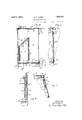
- Figure 1 shows a front elevation of a fireplace embodying my invention.
- Figure 2 shows a horizontal sectional view looking down taken on the line 2-2 of Figure 1.
- Figure 3 shows a detail inverted plan view of a portion of a hearth and ash pan and the adjacent portion of the fireplace.
- Figure 4 shows a vertical central sectional view taken on the line 44 of Figure 1.
- Figure 5 shows a detail sectional View through the front portion of the fireplace 0 illustrating the detachable sheet metal front.
- the dotted lines show this front tilted outwardly for the purpose of removal.
- Figure 6 shows a detail sectional view taken on the line 6-6 of Figure 4.
- Figure 7 shows a detail horizontal sectional view on the line 7--7 of Figure 1.
- my improved fireplace comprises essentially a back, two sides and an open front.
- the back is formed of a piece of flat sheet metal 10 with two upright angle bars 11 connected thereto, preferably by spot welding. These angle bars extend downwardly below the back to form legs, and portions of the angle bars extend forwardly beyond the sheet metal back.
- an angle bar 12 connected to the back, preferably by spot welding, and having its lower portion extended forwardly to form a support for the fireplace bottom, and at the top there is another angle bar 13 secured to the back and having its top flange extended forwardly.
- Each of the two sides comprises a flat sheet metal body 14 having two channel bars 15 and 16 permanently secured thereto on the inner face thereof. These brace and support the side members against warping and also form means by which the detachable back plate and the detachable side plates are held in position.
- each side member 14 At the bottom of each side member 14 is an angle bar 14a with its bottom edge extendedinwardly, and at the top there is an angle bar 14?) at its top edge extending inwardly,
- a detachable back plate 17 made of fiat sheet metal and having angle bars 18 permanently fixed to it with one edge extending rearwardly and forming a spacing means for holding the detachable back plate 17 from the back lO V r
- the side edges of the detachable back member 17 engage the rear member of the-channel 15, thus preventing forward movement of said detachable plate, and by this means it is obvious that the channel bar 15 serves the double function of reinforcing the side members to which it is attached, and supporting the detachable back plate against forward movement.
- detachable inner side plates each of which is made of a piece of fiat sheet metal 19 having two angle bars 20 fixed to it for reinforcing; purposes. These angle bars have one member extended outwardly to space the side plate 19 from the side wall 14.
- the forward upright member of the channel bar 15 is inclined forwardly and the rear upright edge of the plate 19 is inclined rearwardly and outwardly at 21 to pass under the adjacent part of the channel bar 15, thus forming a means for preventing inward movement of the plate 19, and the front edge of the plate 19 is inserted in the channel bar 16, so that it is firmly and immovably held in position and yet readily detached by drawing it upwardly.
- the sides of the fireplace are connected at the front by a transverse metal strip 22 having fixed to its top an angle bar 23 and having fixed to its bottom an angle bar 24, and fixed to the front edge of the angle bar 24 are two upright arms 25 to receive the detachable front panel as will be hereinafter explained.
- These angle bars 23 and 24 are firmly secured by screws or the like to the lower front portion of the fireplace side walls, thus firmly bracing and supporting them at the bottom.
- a similar strip 26 is providedat the top and it also is bolted to the top front edges of the side walls. It is provided near its lower 7 portion with pins 27. These pins are for the purpose of supporting a detachable fireplace front member 26 which is formed of a single sheet of metal and is provided with slots 29 to receive the pins 27 as shown in Figure 5,
- the fireplace bottom is formed of a single sheet of flat metal 30 having across the central portion of its top an angle bar 31 and across the central portion of its under side an angle bar 32 arranged at right angles to each other.
- the bottom is of such size that it will fit within and rest upon the angle bar 12 at the back and the angle bars 14a at the sides, and the angle bar 24 at the front.
- the fireplace'top is formed of a single flat sheet 33 having its margins inclined downwardly at 34 and having a stove pipe collar 35 near its rear side. On the under side of this top member there is a central transverse angle 37 running from side to side.
- the fireplace health is formed of sheet metal and comprises abottom 38, an upturned front 39 and upturned ends 40. On its under side it is provided with two lengthwise angle bars 41 firmly secured to it by spot welding or the like, andhaving their end portions extended downwardly to form the legs 42.
- the inner edge of the hearth member projects a considerable distance under the front of the stove and between the stove legs, so that these stove legs at the front prevent all movement of the hearth member, except a movement straight outwardly.
- the deflector plate for directing the products of combustion upwardly and forwardly within the fireplace is formed of a piece of flat metal 43 having angle bars 44 on its under side and an angle bar 45 at its top, and this rests upon and is supported by the top edges of side plates 19 and needs no other support.
- the fireplace may be readily and easily assembled' by unskilled workmen by first setting up the back member 10. Then the side members 14 are attached by screws or the like passing through the angle bars 11 and the rear edges of the sides 14. Then the two front members 22 and 26 may be placed in position and secured by screws to the front edges of the side members. Then the bottom member 14a is simply placed in position and does not need any fastening means. Then the rear inner wall 17 is slipped into position from above and needs no fastening means. Then the detachable side plates 19 areslipped into position from above and need no fastening.
- the deflector plate 43 is placed in position and needs no fastener.
- the top member is placed in position and fastened with screws into the angle bars at the top of the fireplace. The hearth is simply slipped into position between front le s of the fire place and needs no fastening.
- My improved hearth member is so arranged that surplus ashes from the interior of the fireplace may be scraped out on to it until it is completely filled. Then the operator may remove them by sliding the hearth straight forwardly until it is clear of the stove leg, and then it may be carried to a point of discharge and readily and easily replaced in position. In practice I have found that it is never displaced by accidental means, because nearly all of the blows to which it is subjected tend to push it in under the stove or laterally, and it is only removable When a straight forward pull is applied to it.
- a sheet metal back portion angle bars firm- 1y fixed to the side edges thereof and having portions extending forwardly therefrom, said angle bars being projected below the back to form' legs
- sheet metal side portions having their rear edges detachably connected to the forwardly extending parts of said angle bars and being provided with reinforcing bars on their inner surfaces near their rear edges
- an inner back member formed of sheet metal reinforced by angle bars firm- 1y secured thereto and extended rearwardly to space it from the rear wall and having its side edges engaging the said bars 011 the inner surfaces of the side walls to prevent its forward movement.
- a sheet metal back portion angle bars firmly fixed to the side edges thereof and having portions extending forwardly therefrom, said angle bars being projected below the back to form legs
- sheet metal side portions having their rear edges detachably connected to the forwardly extending parts of said anglebars and being provided withreinforcingbars on their inner surfaces near their rear edges
- an inner back member formed of sheet metal reinforced by angle bars firmly secured thereto and extended rearwardlyto space it from the rear wall and having its side edges engaging the said bars on the inner surfaces of the side walls to prevent its forward movement
- a second reinforcing bar fixed to the side wall at a point in front of the first mentioned bar, and an inner wall having fixed thereto angle bars to space it from the side wall, the front and rear edges of said inner wall being detachably fitted into said reinforcing bars on the side wall, whereby they may be removed by an upward movement.
- a sheet metal back portion angle bars firmly fixed to the side edges thereof and having portions extending forwardly therefrom, said angle bars being projected below the back to form legs
- sheet metal side portions having their rear edges detachably connected to the forwardly extending parts of said angle bars and being provided with reinforcing bars on their inner surfaces near their rear edges
- an inner back member formed of sheet metal reinforced by angle bars firmly secured thereto and extended rearwardly to space it from the rear wall and having its side edges engaging the bars on the inner surfaces of the side walls to prevent its forward movement
Description
April 5, 1932. a F. ELBERT 1,852,404
PORTABLE FIREPLACE Filed April 21, 1950 2 Sheets-Sheet l April 5, 1932. B- ELBERT 1,852,404
PORTABLE FIREPLACE Filed April 21, 1950 2 Sheets-Sheet 2 a t x 7 Ag Zw I a w '0 31/ 2 5a fawn/0r fiFfi/eri Patented Apr. 5, 1932 UNITED STATES BENJAMIN F. ELBERT, OI DES MOINES, IOWA PORTABLE FIREPLACE Application filed April 21,
The object of my invention is to provide a portable fireplace of simple, durable and inexpensive construction, and so arranged that it can be manufactured in sections and shipped in the fiat, and readily, quickly and easily assembled by unskilled workmen, and when assembled will be rigid and durable and bodily portable.
More specifically it is my object to provide a fireplace of this class in which the parts to which the greatest amount of heat is applied are readily and easily removable and replace able.
A further object is to provide a fireplace of (this character in which each unit which is subjected to intense heat is made up of sheet metal and angle bar braces spot welded or otherwise secured thereto, the braces being so shaped and arranged that they will per-. form the additional function of assembling units for connecting the parts together, an which are so arranged relative to the sheet metal that when the inevitable expansion and sagging of the sheet metal takes place under intense heat, the combined actlon of the braces and sheet metal will upon cooling restore the sheet metal to its original condition. A further object is to provide a fireplace of this character in which the inevitable expansion and contraction of the parts to which intense heat is subjected will, during contraction and expansion, not in any way interfere with or distort the main frame member.
A further object is to provide an improved combined hearth and ash pan so arranged that it will perform the usual functions ofa hearth and at the same time serve as a detachablc ash pan into which the ashes within the fireplace may be readily and easily scraped into the hearth, and then the hearth bodily removed for dumping the ashes.
My invention consists in the construction, arrangement and combination of the various parts of the device, whereby the objects contemplated are attained, as hereinafter more 1930. Serial N0. 445,955.
fully set forth, pointed out in my claims, and illustrated in the accompanying drawings, in which:
Figure 1 shows a front elevation of a fireplace embodying my invention.
Figure 2 shows a horizontal sectional view looking down taken on the line 2-2 of Figure 1.
Figure 3 shows a detail inverted plan view of a portion of a hearth and ash pan and the adjacent portion of the fireplace.
Figure 4 shows a vertical central sectional view taken on the line 44 of Figure 1.
Figure 5 shows a detail sectional View through the front portion of the fireplace 0 illustrating the detachable sheet metal front. The dotted lines show this front tilted outwardly for the purpose of removal.
Figure 6 shows a detail sectional view taken on the line 6-6 of Figure 4; and
Figure 7 shows a detail horizontal sectional view on the line 7--7 of Figure 1.
Referring to the accompanying drawings, it will be seen that my improved fireplace comprises essentially a back, two sides and an open front. The back is formed of a piece of flat sheet metal 10 with two upright angle bars 11 connected thereto, preferably by spot welding. These angle bars extend downwardly below the back to form legs, and portions of the angle bars extend forwardly beyond the sheet metal back.
At the bottom edge of the back 10 there is an angle bar 12 connected to the back, preferably by spot welding, and having its lower portion extended forwardly to form a support for the fireplace bottom, and at the top there is another angle bar 13 secured to the back and having its top flange extended forwardly. 85
Each of the two sides comprises a flat sheet metal body 14 having two channel bars 15 and 16 permanently secured thereto on the inner face thereof. These brace and support the side members against warping and also form means by which the detachable back plate and the detachable side plates are held in position.
At the bottom of each side member 14 is an angle bar 14a with its bottom edge extendedinwardly, and at the top there is an angle bar 14?) at its top edge extending inwardly,
Referring to Figure 7 of the drawings there is illustrated a detachable back plate 17 made of fiat sheet metal and having angle bars 18 permanently fixed to it with one edge extending rearwardly and forming a spacing means for holding the detachable back plate 17 from the back lO V r The side edges of the detachable back member 17 engage the rear member of the-channel 15, thus preventing forward movement of said detachable plate, and by this means it is obvious that the channel bar 15 serves the double function of reinforcing the side members to which it is attached, and supporting the detachable back plate against forward movement.
There are two detachable inner side plates, each of which is made of a piece of fiat sheet metal 19 having two angle bars 20 fixed to it for reinforcing; purposes. These angle bars have one member extended outwardly to space the side plate 19 from the side wall 14.
The forward upright member of the channel bar 15 is inclined forwardly and the rear upright edge of the plate 19 is inclined rearwardly and outwardly at 21 to pass under the adjacent part of the channel bar 15, thus forming a means for preventing inward movement of the plate 19, and the front edge of the plate 19 is inserted in the channel bar 16, so that it is firmly and immovably held in position and yet readily detached by drawing it upwardly.
The sides of the fireplace are connected at the front by a transverse metal strip 22 having fixed to its top an angle bar 23 and having fixed to its bottom an angle bar 24, and fixed to the front edge of the angle bar 24 are two upright arms 25 to receive the detachable front panel as will be hereinafter explained. These angle bars 23 and 24 are firmly secured by screws or the like to the lower front portion of the fireplace side walls, thus firmly bracing and supporting them at the bottom.
A similar strip 26 is providedat the top and it also is bolted to the top front edges of the side walls. It is provided near its lower 7 portion with pins 27. These pins are for the purpose of supporting a detachable fireplace front member 26 which is formed of a single sheet of metal and is provided with slots 29 to receive the pins 27 as shown in Figure 5,
and the bottom rests between the angle bar 23 and the arms 25, as shown in Figure 5. Ordinarily the-fireplace is used without this detachablefront member, but when it is applied, it is obvious that it will completely enclose the fireplace.
The fireplace bottom is formed of a single sheet of flat metal 30 having across the central portion of its top an angle bar 31 and across the central portion of its under side an angle bar 32 arranged at right angles to each other. The bottom is of such size that it will fit within and rest upon the angle bar 12 at the back and the angle bars 14a at the sides, and the angle bar 24 at the front.
The fireplace'top is formed of a single flat sheet 33 having its margins inclined downwardly at 34 and having a stove pipe collar 35 near its rear side. On the under side of this top member there is a central transverse angle 37 running from side to side.
The fireplace health is formed of sheet metal and comprises abottom 38, an upturned front 39 and upturned ends 40. On its under side it is provided with two lengthwise angle bars 41 firmly secured to it by spot welding or the like, andhaving their end portions extended downwardly to form the legs 42. The inner edge of the hearth member projects a considerable distance under the front of the stove and between the stove legs, so that these stove legs at the front prevent all movement of the hearth member, except a movement straight outwardly.
The deflector plate for directing the products of combustion upwardly and forwardly within the fireplace is formed of a piece of flat metal 43 having angle bars 44 on its under side and an angle bar 45 at its top, and this rests upon and is supported by the top edges of side plates 19 and needs no other support.
In practice it is obvious that all of the various parts of the device can be manufac: tured quickly and cheaply and are relatively fiat and will not need crating in shipment. The fireplace may be readily and easily assembled' by unskilled workmen by first setting up the back member 10. Then the side members 14 are attached by screws or the like passing through the angle bars 11 and the rear edges of the sides 14. Then the two front members 22 and 26 may be placed in position and secured by screws to the front edges of the side members. Then the bottom member 14a is simply placed in position and does not need any fastening means. Then the rear inner wall 17 is slipped into position from above and needs no fastening means. Then the detachable side plates 19 areslipped into position from above and need no fastening. Then the deflector plate 43is placed in position and needs no fastener. And finally the top member is placed in position and fastened with screws into the angle bars at the top of the fireplace. The hearth is simply slipped into position between front le s of the fire place and needs no fastening.
efore a fire is made in the fireplace the bottom is covered with a layer or ashes, sand or the like, and when a very hot fire is made, the parts subjected to the most intense heat will expand and tend to warp or bulge. However, these parts are the detachable plates 17 and 19 and the top plate 43, all of which are loosely mounted and the expansion or contraction of these parts will not produce any strains upon the main frame of the fireplace.
I have discovered by actual practice that when these parts have thus expanded and bulged, then when the fireplace again cools off the contraction of the sheet metal and angle bars will again straighten out the sheet metal and return the parts to their approximately normal condition.
In the event, however, that intense heat is applied for too great a length of time, one of these sheet metal parts may burn out, but in that event a new one can be provided and very quickly and easily put in place by an unskilled operator.
My improved hearth member is so arranged that surplus ashes from the interior of the fireplace may be scraped out on to it until it is completely filled. Then the operator may remove them by sliding the hearth straight forwardly until it is clear of the stove leg, and then it may be carried to a point of discharge and readily and easily replaced in position. In practice I have found that it is never displaced by accidental means, because nearly all of the blows to which it is subjected tend to push it in under the stove or laterally, and it is only removable When a straight forward pull is applied to it.
In the drawings I have illustrated the main parts of my improved fireplace as made of sheet metal, and in the drawings and claims I have described these parts as sheet metal members. I do not desire, however, to be understood as limiting my claims to the use of sheet metal, but intend them to be construed as covering mechanical equivalents thereof.
I claim as my invention:
1. In a portable fireplace, the combination of a sheet metal back portion, angle bars firm- 1y fixed to the side edges thereof and having portions extending forwardly therefrom, said angle bars being projected below the back to form' legs, sheet metal side portions having their rear edges detachably connected to the forwardly extending parts of said angle bars and being provided with reinforcing bars on their inner surfaces near their rear edges, and an inner back member formed of sheet metal reinforced by angle bars firm- 1y secured thereto and extended rearwardly to space it from the rear wall and having its side edges engaging the said bars 011 the inner surfaces of the side walls to prevent its forward movement.
2. In a portable fireplace, the combination of a sheet metal back portion, angle bars firmly fixed to the side edges thereof and having portions extending forwardly therefrom, said angle bars being projected below the back to form legs, sheet metal side portions having their rear edges detachably connected to the forwardly extending parts of said anglebars and being provided withreinforcingbars on their inner surfaces near their rear edges, an inner back member formed of sheet metal reinforced by angle bars firmly secured thereto and extended rearwardlyto space it from the rear wall and having its side edges engaging the said bars on the inner surfaces of the side walls to prevent its forward movement, a second reinforcing bar fixed to the side wall at a point in front of the first mentioned bar, and an inner wall having fixed thereto angle bars to space it from the side wall, the front and rear edges of said inner wall being detachably fitted into said reinforcing bars on the side wall, whereby they may be removed by an upward movement.
3. In a portable fireplace, the combination of a sheet metal back portion, angle bars firmly fixed to the side edges thereof and having portions extending forwardly therefrom, said angle bars being projected below the back to form legs, sheet metal side portions having their rear edges detachably connected to the forwardly extending parts of said angle bars and being provided with reinforcing bars on their inner surfaces near their rear edges, an inner back member formed of sheet metal reinforced by angle bars firmly secured thereto and extended rearwardly to space it from the rear wall and having its side edges engaging the bars on the inner surfaces of the side walls to prevent its forward movement, angle bars fixed to the front edges of the side walls and projected below side walls to form legs, cross strips at the upper and lower portions of the front secured to said angle bars at the front edges of said walls, and a flat sheet metal top having reinforcing bars on its under surface secured to the top of the fireplace.
4. In a portable fireplace, the combination of a sheet metal back portion, angle bars firmly fixed to the side edges thereof and having portions extending forwardly therefrom, said angle bars being projected below the back to form legs, sheet metal side portions having their rear edges detachably connected to the forwardly extending parts of said angle bars and being provided with reinforcing bars on their inner surfaces near their rear edges, an inner back member formed of sheet metal reinforced by angle bars firmly secured thereto and extended rearwardly to space it from the rear wall and having its side edges engaging the said bars on the inner surfaces of the side walls to prevent its forward movement, a second reinforcing bar fixed to the side wall at a point in front of the first mentioned bar, an inner wall having fixed there to angle bars to space it from the side wall,
thefront' and rear edges of said inner wall being detachably fitted into said reinforcing bars on the side wall, whereby they may be removedby an upward movement, the upper edgesof said inner side walls being inclined upwardly and forwardly, and a deflector plate formed of flat sheet metal with reinforcing bars firmly fixed to its under and lower surface, detaehably supported on thetop 1 edges of said inner side plates;
Des Moine's, Iowa, March 27,1930.
BENJAMIN F. ELBERT.
Priority Applications (1)
| Application Number | Priority Date | Filing Date | Title |
|---|---|---|---|
| US445955A US1852404A (en) | 1930-04-21 | 1930-04-21 | Portable fireplace |
Applications Claiming Priority (1)
| Application Number | Priority Date | Filing Date | Title |
|---|---|---|---|
| US445955A US1852404A (en) | 1930-04-21 | 1930-04-21 | Portable fireplace |
Publications (1)
| Publication Number | Publication Date |
|---|---|
| US1852404A true US1852404A (en) | 1932-04-05 |
Family
ID=23770802
Family Applications (1)
| Application Number | Title | Priority Date | Filing Date |
|---|---|---|---|
| US445955A Expired - Lifetime US1852404A (en) | 1930-04-21 | 1930-04-21 | Portable fireplace |
Country Status (1)
| Country | Link |
|---|---|
| US (1) | US1852404A (en) |
Cited By (4)
| Publication number | Priority date | Publication date | Assignee | Title |
|---|---|---|---|---|
| US2543869A (en) * | 1947-11-12 | 1951-03-06 | Gen Railway Signal Co | Centralized traffic controlling system |
| US3880139A (en) * | 1973-06-22 | 1975-04-29 | Glenn A Young | Transportable camper fireplace |
| US4150658A (en) * | 1977-03-30 | 1979-04-24 | Arizona Forest Supply, Inc. | Circulating-air heating stove |
| US4230091A (en) * | 1978-08-23 | 1980-10-28 | Carmor Manufacturing Ltd. | Stove |
-
1930
- 1930-04-21 US US445955A patent/US1852404A/en not_active Expired - Lifetime
Cited By (4)
| Publication number | Priority date | Publication date | Assignee | Title |
|---|---|---|---|---|
| US2543869A (en) * | 1947-11-12 | 1951-03-06 | Gen Railway Signal Co | Centralized traffic controlling system |
| US3880139A (en) * | 1973-06-22 | 1975-04-29 | Glenn A Young | Transportable camper fireplace |
| US4150658A (en) * | 1977-03-30 | 1979-04-24 | Arizona Forest Supply, Inc. | Circulating-air heating stove |
| US4230091A (en) * | 1978-08-23 | 1980-10-28 | Carmor Manufacturing Ltd. | Stove |
Similar Documents
| Publication | Publication Date | Title |
|---|---|---|
| US2501104A (en) | Combination grill and grid | |
| US1852404A (en) | Portable fireplace | |
| US3195442A (en) | Portable cooking apparatus | |
| US2722965A (en) | Combination desk-seat unit | |
| US2113082A (en) | Camp stove | |
| US2026387A (en) | Portable stove | |
| US2168944A (en) | Barbecue stove | |
| US2439503A (en) | Air-heating device for fireplaces | |
| US2060339A (en) | Cooking stove | |
| US1594290A (en) | Watering trough | |
| US2140924A (en) | Folding camp stove | |
| US2214292A (en) | Camp stove | |
| US787403A (en) | Foot-warmer. | |
| GB486979A (en) | Improvements relating to bed-tables | |
| US1865313A (en) | Chair seat | |
| US2646787A (en) | Hot-air circulating attachment for cook stoves | |
| US1473703A (en) | Kitchen cabinet | |
| US1546945A (en) | Gas heater | |
| US1645223A (en) | Furnace | |
| US1519011A (en) | Radiator shield | |
| US1373562A (en) | Gas-stove | |
| US1880205A (en) | Broiling apparatus | |
| US1200919A (en) | Brush-burner. | |
| US1558821A (en) | Furnace air-supply construction | |
| US2165038A (en) | Hot air heater |