US1852395A - Signaling system for railroads - Google Patents
Signaling system for railroads Download PDFInfo
- Publication number
- US1852395A US1852395A US477286A US47728630A US1852395A US 1852395 A US1852395 A US 1852395A US 477286 A US477286 A US 477286A US 47728630 A US47728630 A US 47728630A US 1852395 A US1852395 A US 1852395A
- Authority
- US
- United States
- Prior art keywords
- train
- switch
- relay
- track
- route
- Prior art date
- Legal status (The legal status is an assumption and is not a legal conclusion. Google has not performed a legal analysis and makes no representation as to the accuracy of the status listed.)
- Expired - Lifetime
Links
Images
Classifications
-
- B—PERFORMING OPERATIONS; TRANSPORTING
- B61—RAILWAYS
- B61L—GUIDING RAILWAY TRAFFIC; ENSURING THE SAFETY OF RAILWAY TRAFFIC
- B61L25/00—Recording or indicating positions or identities of vehicles or vehicle trains or setting of track apparatus
- B61L25/06—Indicating or recording the setting of track apparatus, e.g. of points, of signals
Definitions
- This invention relates to signaling systems for railroads, and more particularly to a system by which the operator or leverman, controlling the track switch as the junction point of diverging routes, may be advised of the route to be set up for approaching trains.
- a poweroperatcd switch of the usual type assumed to be located at a point of diverging routes and conveniently termed a junction switch, is diagrammatically shown and designated Sil
- the particular means employed for operating this switch, under the control of a distant operator or leverman, is not material to the present invention, and no attempt has been made to show any particular construction or arrangement of parts for accomplishing this result.
- Train movements toward the switch SW in the direction of traffic indicated by the arrow, are governed in the usual way by block signals, such as 1, 2, and 3, and an interlocked signal having the usualupper and lower arms el and 4A.
- the control circuits for these signals being ofany one of the wellknown types, arenot shown.
- These signals govern traffic through blocks or track circuit sections A, B, and C, each having a track relay shown conventionally as a dotted line and designated 1T, QT, and 31.
- this hand-switch HS is assumed to be located at or adjacent to a station ST in the rear of the signal 1. While the three blocks A, B, and C have been illustrated between the switch SW and the point Where the switch HS is located, the system may be extended to include a territory comprising any desired number of track circuit sections or blocks,
- the hand switch HS may be arranged to be operated by the train dispatcher or starter by the conductor or trainman of the train stopping at this station, or may be located on a post or the like along the track within convenient reach of the engineman or motorman of the train, or it may be operated in some suitable manner, not shown, by means associated with the train itself.
- Stick relay SR and SN controlled by the hand switch HS and the track relay OT of a track section 0 in the rear of the signal 1 and opposite the station ST, are preferably employed in the manner hereinafter explained, so that this hand switch HS must be operated for each train before the signal 1 can be cleared.
- the apparatus located in the tower or con trol office which has been shown as included in a dash rectangle CO, comprises a track diagram TD of any usual type which is provided with a plurality of pairs of indicatresponding with ing lamps a-1 and a-2, b-1, b2, etc. There is one pair of such indicating lamps for each of the blocks A, B, and C in the rear of the switch SWV. These indicating lamps of each pair may be located above and below the line on the track diagram indicating the track, or may have distinctive colors, or may be made distinguishable in any other suitable way so as to indicate whether the switch SW should be in the normal or in the reverse position to correspond with the route to be taken by the approaching train in the corresponding block.
- These pairs of indicating lamps a1 and a2, etc. are controlled by indication relays 1B, 2B, and 3B, and by track relay repeater relays 1T1 2T1 and 3TP.
- Each of these indicating relays, such as 1B is of the deadbeat polar type, its contact fingers being shifted from one extremeposition to the other in accordance with the polarity of energization of the relay, and being held in either extreme position by the attraction of the permanent magnet of the relay until shifted to the other extreme position.
- the track relay repeater relays such as lTP, are energized in the usual way through front contacts of the corresponding track relay, as 1T, as indicated by dotted lines, so that each track relay repeater relay is energized if the corresponding block or track circuit section is clear 0 trains and is de-energized if said block or track circuit section is occupied by a train.
- the tower apparatus also includes levers, together with associated mechanical interlocking and other auxiliary devices, by which the leverman controls the position of the switch SW and the indications of the signals a and 4A.
- levers and associated apparatus being of the usual type and well-known in the art, have not been shown.
- switch HS After the switch HS has thus been shifted to a position corresponding to the route to be taken by the train, it is restored to the normal position, whereupon a circuit for clearing the signal 1 is established from (-1-) contact finger 9 of switch HS in the middle position, wires 16 and 17, front contact 18 of relay SN, wires 19 and 20, front contact 21 of track relay 1T, wire 22, signal 1, and
- the indication relay 1B With the relay SN energized, and with no train in the block A, the indication relay 1B is energized positively over a circuit from B front contact 25 of relay SN, wire 26, front contact 27 of relay 1T1 wire 28, relay 13 to N, in licating a mid-tap or neutral point of a battery or other source of current.
- This positive energization of the relay 1R positions its contact fingers 29 and 30 to the right; and if there is no train in the block B, in the case assumed, the next indication relay 2B is energized positively over a circuit from B contact 30 of relay 1R to the right, wire 81, front contact 32 of relay 2T1 wire 33, relay 23, to N.
- the indicating lamp a-2 is lighted over a circuit from back contact 40 of relay 1T1 wire 41, contact 29 of relay 1R to the right, wire 42, lamp a-2, to The lighting of the lamp a-2 shows that a train is present in the block A, and also shows that the route desired for this train is over the switch SW in the nor mal position.
- the lamp b2 is lighted through the back contact 4t3 of the relay 21?, in the same way as the lamp M2 is lighted; and when the rear end of this train leaves the block A, and the relay lTP is energized, its back contact opens and extinguishes the lamp. (e 2. Similarly, when the train advances into the block C, the lamp c-2 is lighted and the lamp b-2 extinguished.
- the switch HS would be thrown to the right, moving its contact finger 9 to the left, and energizing the: stick relay SR over circuits analogous to those for the relay SN above explained.
- the indication relay 1B With the relay SR energized, the indication relay 1B is energized negatively over a circuit from B front contact of relay SR, wire 46, back contact 25 of relay SN, wire 26, etc. the same as in the circuit above traced. This positions the contact fingers of the relays 1H, 2H, and SE to the left-hand position, and results in lighting the lamps a-1, 61, c l, as the train advances through the blocks A, B, and C.
- the route forthe first train is set up in the manner just explained; and as this train advances into and through the several blocks A, B, and C, the presence of this train and its desired route is indicated by the lighting of the indicating lamp in the same manner above explained.
- the stick relay SN or SR as the case may be, is deellergized; and before the signal 1 can again be cleared to permit the second, following, train to advance, the switch HS must be again operated to one position or the other, corres 'ionding to the desired route for this second train, to pick up the relay SN or SR.
- the relay lTP When the first train leaves the block A, the relay lTP is energized and closes its front contact 27, so that the indication relay 1R nmy be emergized either positively or negatively depending upon the route desired for the second train.
- the signal 1 may clear, and the second train may advance. lVhen this second train enters the block A, the relay lTP is again (lo-energized, closing its back contact 40, to light the indicating lamp a-1 or -12, as the case may be, in accordance with the route set up for this second train.
- the relay 2T]? may pick up, and permit energizetion of the relay 2R in accordance with the position of the contact finger 30 of the relay 1B, which corresponds with the route for the second train; and when this second train advances into the block B. the indicating lamp Z)1 or b-2 is lighted.
- the relays SN and SR assure movement of the control switch HS for each train, and prevent this switch being left in one position or the other accidentally or carelessly, while two. ormore trains pass.
- These stick relays SN and SR are provided so that the switch HS may be shifted to the proper extreme position and then at once returned to the normal position; but ifdesired', these stick relays may be omitted, and a springa-eturned switch HS used to controlthepolarity of energization of the first indication relay JR and the clearing of the signal 1, although such an arr-ange ment requires that the switch HS be held in its operated position until the signal 1 has cleared.
- the control ofthe signal 1 by the switch HS may be omitted, and this switch shifted back and forth by the train starter or dispatcher, atower man, or other individual, as may be required for each train as it passes.
- the provision of the stick relays SN and SR be preferable, however, for most applications of the invention, particularly where the switch HS is located on the track and is intended to be manipulated bythe engineman or motorman.
- a train annunciator system the combination with a track switch and a plurality of track circuit sections in the rear thereof, of a track diagram having indicating means for each track section capable of giving two distinctive indications corresponding to different positions of said switch, and means for governing said indicating means in accordance with the presence of trains in said track circuit sections and in accordance with the respective routes over said switch to be taken by said trains.
- a train annunciator system the combination with a track switch and a plurality of track circuit sections in the rear thereof, of a track diagram having indicating means for each track section for showing the presence of a train on that track section and also the route to be taken by that train over said switch, and automatic means for changing said indicating means for each track section as difierent trains enter that track section to correspond with the route to be taken by each train.
- a train annunciator system combination, a track switch and a plurality of track circuit sections, a plurality of route indicating lamps, a manually operable device movable to difi'erent positions in accordance with the route taken by a train over said switch, and means governed by said device and also by the track circuits of said track sections for controlling said route lamps.
- a track diagram having indicating means for indicating the routes to'be taken by a plurality of trains, a manually operable device for setting up the route to be taken by each train, and means governed by said device and by track circuits for controlling said indicating means.
- a track diagram having a plurality of pairs of indicating lamps, each pair of lamps corresponding to a predetermined section of track and being capable of giving distinctive indications to indicate the route to be taken by a train occupying said corresponding track section, and means for controlling said lamps comprising a manually operable device and relaysresponsive to the presence of trains on said track sections.
- a track diagram having'a pair of indicating lamps for each block, control means for each pair of lamps for selecting the lamp of that pair to be lighted, and a means responsive to the presence of trains in each block for governing said control means of the pair of indicating lamps for the corresponding block and for lighting one of said lamps when the correspon ing block is occupied.
- a train annunciator system the combination with a track switch and a plurality of blocks in the rear thereof, of a track diagram having a pair of indicating lamps for each block, a polar'relay for each pair 0 lamps and having a dead-beat contact finger selecting the lighting circuits for said lamps, a repeater track relay for each block de-energized by the presence of a train thereon, an
- each energizing circuit for each polar relay including a front contact of the repeater track relay of the corresponding block, and a lighting circuit for each pair. of lamps including a back contact of the repeater track relay of the corresponding block.
- a wayside signal a manually operable switch adjacent said signal, route indicating means, and means governed by said switch and a track circuit adjacent said signal for governing said route indicating means and also said signal.
- control means including a manually operable switch for governing said indicating means, a track switch and awayside signal adjacent to the point where said switch is located, said control means being rendered inefiective by the movel ment of a train over said track circuit, and means for permitting clearing of said signal only if said control means is efiective an said switch is in an inactive conditon, where- V by said switch must be operated after the passage of a train over said track circuit in order to clear said signal for another following train.
- indicating means for showing the routes to be taken by a plurality of trains, a stick relay governing said indicating means, a control switch, a wayside signal and a track circuit adjacent the point where said control switch is located, 7
- pick-up and stick circuits for said relay controlled by said track circuit, said pick-up circuit including a contact of said control switch closed in an operated position, and a clearing circuit for said signal closed only when said stick relay is energized and said control switch is in a normal non-operated position.
- I indlcating means for each track section capable of giving two distinctive indications correspondng to different positions of said switch, and means for governng said indicating means in accordance with the presence of trains in said track circuit sections and in accordance with the respective route over said switch to be taken by said trains.
- each pair of lamps corresponding to a predetermined section of track and being cap dlstlnctlve lndlcatlons to 1nd1 presence of trai
- correend means for conmps comprlslng a manually ponsive t0 the ms 011 said track sect-ions.
Description
April 5, 1932. F. BENEDICT SIGNALING SYSTEM FOR RAILROADS Filed Aug. 23, 1950 tion to another.
Patented Apr. 5, 1932 UNITED STATES FRANK BENEDICT,
PATENT OFFICE OF RUTHERFORD, NEW JERSEY, ASSIGNOR. T GENERAL RAILWAY SIGNAL COMPANY, OF ROCHESTER, NEW
YORK
SIGNALING SYSTEM FOR RAILROADS Application filed August 23, 1930. Serial No. 477,286.
This invention relates to signaling systems for railroads, and more particularly to a system by which the operator or leverman, controlling the track switch as the junction point of diverging routes, may be advised of the route to be set up for approaching trains.
Where trains for different destinations approach a junction point for different routes at frequent intervals, as on subways, in railroad terminals, and the like, it is very helpful to the leverman or operator who is controlling the position of the switch or switches at such junction point, to know in advance which route each train approaching is to take.
In accordance with the present invention, it proposed to indicate on a track diagram before the operator, at points corresponding to the blocks or track circuit sections, the presence of each train approaching a junction switch, and also the route respective trains are to take, theindications of the presence of a given train and its route being automatically changed on the track diagram as this train advances from one block or track circuit see- This indicating means on the track diagram is conditioned for opera tion to show the route to be taken by each train by means of a suitable manually operable device, located at a station or other point at which each train has to stop or pass prior to reaching the junction switch.
Various other characteristic features, functions, and advantages of the invention will be in part apparent, and in part pointed out as the description progresses.
The accompanying drawing illustrates in a simplified and diagrammatic manner one specific embodiment of the invention.
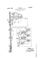
In the accompanying drawing, a poweroperatcd switch of the usual type, assumed to be located at a point of diverging routes and conveniently termed a junction switch, is diagrammatically shown and designated Sil The particular means employed for operating this switch, under the control of a distant operator or leverman, is not material to the present invention, and no attempt has been made to show any particular construction or arrangement of parts for accomplishing this result. Any suitable system of at the station ST, or
manual or power operation and control for the switch Sl V, commonly used in the art, is suitable for this purpose.
Train movements toward the switch SW in the direction of traffic indicated by the arrow, are governed in the usual way by block signals, such as 1, 2, and 3, and an interlocked signal having the usualupper and lower arms el and 4A. The control circuits for these signals, being ofany one of the wellknown types, arenot shown. These signals govern traffic through blocks or track circuit sections A, B, and C, each having a track relay shown conventionally as a dotted line and designated 1T, QT, and 31.
ocated at'a suitable point in the rear of the switch SW is a suitable manually operable device or hand switch HS. As diagrammatically shown, this hand-switch HS is assumed to be located at or adjacent to a station ST in the rear of the signal 1. While the three blocks A, B, and C have been illustrated between the switch SW and the point Where the switch HS is located, the system may be extended to include a territory comprising any desired number of track circuit sections or blocks,
The hand switch HS may be arranged to be operated by the train dispatcher or starter by the conductor or trainman of the train stopping at this station, or may be located on a post or the like along the track within convenient reach of the engineman or motorman of the train, or it may be operated in some suitable manner, not shown, by means associated with the train itself.
Stick relay SR and SN, controlled by the hand switch HS and the track relay OT of a track section 0 in the rear of the signal 1 and opposite the station ST, are preferably employed in the manner hereinafter explained, so that this hand switch HS must be operated for each train before the signal 1 can be cleared.
The apparatus located in the tower or con trol office, which has been shown as included in a dash rectangle CO, comprises a track diagram TD of any usual type which is provided with a plurality of pairs of indicatresponding with ing lamps a-1 and a-2, b-1, b2, etc. There is one pair of such indicating lamps for each of the blocks A, B, and C in the rear of the switch SWV. These indicating lamps of each pair may be located above and below the line on the track diagram indicating the track, or may have distinctive colors, or may be made distinguishable in any other suitable way so as to indicate whether the switch SW should be in the normal or in the reverse position to correspond with the route to be taken by the approaching train in the corresponding block.
These pairs of indicating lamps a1 and a2, etc. are controlled by indication relays 1B, 2B, and 3B, and by track relay repeater relays 1T1 2T1 and 3TP. Each of these indicating relays, such as 1B, is of the deadbeat polar type, its contact fingers being shifted from one extremeposition to the other in accordance with the polarity of energization of the relay, and being held in either extreme position by the attraction of the permanent magnet of the relay until shifted to the other extreme position. The track relay repeater relays, such as lTP, are energized in the usual way through front contacts of the corresponding track relay, as 1T, as indicated by dotted lines, so that each track relay repeater relay is energized if the corresponding block or track circuit section is clear 0 trains and is de-energized if said block or track circuit section is occupied by a train.
The tower apparatus also includes levers, together with associated mechanical interlocking and other auxiliary devices, by which the leverman controls the position of the switch SW and the indications of the signals a and 4A. Such levers and associated apparatus, being of the usual type and well-known in the art, have not been shown.
0peration.-The parts are shown in the accompanying drawing in what may be termed the normal condition, that is, when there are no trains approaching the track switch SlV within the territory of the train annunciator system. In this normal condition, the hand switch HS is in the intermediate or middle "position, to which it is preferably biased by a spring orother suitable means. The relays 1T1 2TP, and 3T]? are all energized, and the indicating lamps a1, and 0;2, etc. are all extinguished.
Assume now that a train, having a destination which requires that the track switch SlV should be set in the normal position, approaches and stops at the station ST, or corresponding point, where the control switch HS is located. The switch HS is now operated by the motorman of the train, the train starter, or other individual, to a position corthe route over which the 'train should pass. As shown, it is assumed that the switch HS will be shifted to the left to correspond with the switch SlV normal;
and when the switch HS is placed in this left-hand position, with a train on the track section Q, the contact finger 9 of this switch is moved to the right and the stick relay SN is energized by a pick-up circuit from contact finger 9 of switch HS to the right, wires 10 and 11, relay SN, wire 12, back contact 13 of track relay OT, to The relay SN is stuck up by a stick circuit from front contact 1A of relay SN, wires 15 and 11, relay SN, wire 12, and back contact 13 of track relay OT, to
After the switch HS has thus been shifted to a position corresponding to the route to be taken by the train, it is restored to the normal position, whereupon a circuit for clearing the signal 1 is established from (-1-) contact finger 9 of switch HS in the middle position, wires 16 and 17, front contact 18 of relay SN, wires 19 and 20, front contact 21 of track relay 1T, wire 22, signal 1, and
thence through such other controlling c0ntacts as may be required (indicated diagrammatically at 28), to
With the relay SN energized, and with no train in the block A, the indication relay 1B is energized positively over a circuit from B front contact 25 of relay SN, wire 26, front contact 27 of relay 1T1 wire 28, relay 13 to N, in licating a mid-tap or neutral point of a battery or other source of current. This positive energization of the relay 1R positions its contact fingers 29 and 30 to the right; and if there is no train in the block B, in the case assumed, the next indication relay 2B is energized positively over a circuit from B contact 30 of relay 1R to the right, wire 81, front contact 32 of relay 2T1 wire 33, relay 23, to N. This in turn positions the contact fingers 34 and35 of the relay 211 to the right-hand or positive position, and causes energization of the relay 3R- over a circuit from B contact finger 35 of relay 2R to the right, wire 36, front contact 37 of relay 3T1, wire 38, relay 3K, to N.
Thus, movement of the control switch HS to a position corresponding to the switch SW normal is registered, so to speak, by the posi tive energization of the indication relays 1B, 2B, and 3B and the positioning of their contact fingersto the right. i
hen the train ii -question enters the block A and drops the relay lTP, the indicating lamp a-2 is lighted over a circuit from back contact 40 of relay 1T1 wire 41, contact 29 of relay 1R to the right, wire 42, lamp a-2, to The lighting of the lamp a-2 shows that a train is present in the block A, and also shows that the route desired for this train is over the switch SW in the nor mal position.
hen the train in question advances into the block l3 and drops the relay 2TP, the lamp b2 is lighted through the back contact 4t3 of the relay 21?, in the same way as the lamp M2 is lighted; and when the rear end of this train leaves the block A, and the relay lTP is energized, its back contact opens and extinguishes the lamp. (e 2. Similarly, when the train advances into the block C, the lamp c-2 is lighted and the lamp b-2 extinguished.
If the approaching train should have a destination requiring the switch SW to be placed in the reverse position, than the switch HS would be thrown to the right, moving its contact finger 9 to the left, and energizing the: stick relay SR over circuits analogous to those for the relay SN above explained. With the relay SR energized, the indication relay 1B is energized negatively over a circuit from B front contact of relay SR, wire 46, back contact 25 of relay SN, wire 26, etc. the same as in the circuit above traced. This positions the contact fingers of the relays 1H, 2H, and SE to the left-hand position, and results in lighting the lamps a-1, 61, c l, as the train advances through the blocks A, B, and C.
Considering new the case where several trains for the same or different destinations may be following each other closely, the route forthe first train is set up in the manner just explained; and as this train advances into and through the several blocks A, B, and C, the presence of this train and its desired route is indicated by the lighting of the indicating lamp in the same manner above explained. When this first train leaves the track section and the track relay OT picks up, the stick relay SN or SR, as the case may be, is deellergized; and before the signal 1 can again be cleared to permit the second, following, train to advance, the switch HS must be again operated to one position or the other, corres 'ionding to the desired route for this second train, to pick up the relay SN or SR.
When the first train leaves the block A, the relay lTP is energized and closes its front contact 27, so that the indication relay 1R nmy be emergized either positively or negatively depending upon the route desired for the second train. When the first-train passes out of the block A, the signal 1 may clear, and the second train may advance. lVhen this second train enters the block A, the relay lTP is again (lo-energized, closing its back contact 40, to light the indicating lamp a-1 or -12, as the case may be, in accordance with the route set up for this second train.
-FVhen the first train leaves the block B, the relay 2T]? may pick up, and permit energizetion of the relay 2R in accordance with the position of the contact finger 30 of the relay 1B, which corresponds with the route for the second train; and when this second train advances into the block B. the indicating lamp Z)1 or b-2 is lighted.
The same procedure and mode of operation is followed for each succeeding train; and
with three blocks A, B and O between the switch SW and the point where the control switchlIS is located, provision is made for indicating the presence and desired route for trains. In this way the operator knows exactly what trains are coming, how far each train has advanced, a-ndhas such full information to control the switch SW, as well as the various other switches and signals for various routes, as enables himtomanipulate his levers in such a way as to reduce train delays to a minimum. The operator can tell at a glance from the track diagram how many trains are approaching, how many require one route, and how many another route and he may efficiently govern the switches and signals accordingly. The presence of any desired number of trains and their respective routes may be indicated on the trackdiagram by duplicating the apparatus and circuits shown; and it should be understood that the arrangement shown, providing for trains in three blocks, is merely typical.
The relays SN and SR, and their associated circuits, assure movement of the control switch HS for each train, and prevent this switch being left in one position or the other accidentally or carelessly, while two. ormore trains pass. These stick relays SN and SR are provided so that the switch HS may be shifted to the proper extreme position and then at once returned to the normal position; but ifdesired', these stick relays may be omitted, and a springa-eturned switch HS used to controlthepolarity of energization of the first indication relay JR and the clearing of the signal 1, although such an arr-ange ment requires that the switch HS be held in its operated position until the signal 1 has cleared. Also, if desired, the control ofthe signal 1 by the switch HS may be omitted, and this switch shifted back and forth by the train starter or dispatcher, atower man, or other individual, as may be required for each train as it passes. The provision of the stick relays SN and SR, be preferable, however, for most applications of the invention, particularly where the switch HS is located on the track and is intended to be manipulated bythe engineman or motorman. r
The particular construction and arrangement of parts and circuits shown and described is susceptible to variousmodifications, adaptations and additions, without departing from the invention.
as shown, is considered to What I claim is 1. In a train annunciator system, the combination with a track switch and a plurality of track circuit sections in the rear thereof, of a track diagram having indicating means for each track section capable of giving two distinctive indications corresponding to different positions of said switch, and means for governing said indicating means in accordance with the presence of trains in said track circuit sections and in accordance with the respective routes over said switch to be taken by said trains. 1
2. In a train annunciator system, the combination with a track switch and a plurality of track circuit sections in the rear thereof, of a track diagram having indicating means for each track section for showing the presence of a train on that track section and also the route to be taken by that train over said switch, and automatic means for changing said indicating means for each track section as difierent trains enter that track section to correspond with the route to be taken by each train.
3. In a train annunciator system, combination, a track switch and a plurality of track circuit sections, a plurality of route indicating lamps, a manually operable device movable to difi'erent positions in accordance with the route taken by a train over said switch, and means governed by said device and also by the track circuits of said track sections for controlling said route lamps.
4. In a system of the type described, a track diagram having indicating means for indicating the routes to'be taken by a plurality of trains, a manually operable device for setting up the route to be taken by each train, and means governed by said device and by track circuits for controlling said indicating means.
5. In a system of the type described, a track diagram having a plurality of pairs of indicating lamps, each pair of lamps corresponding to a predetermined section of track and being capable of giving distinctive indications to indicate the route to be taken by a train occupying said corresponding track section, and means for controlling said lamps comprising a manually operable device and relaysresponsive to the presence of trains on said track sections.
6. In a train annunciator system, the combination with a track switch and a plurality of blocks in the rear thereof, a track diagram having'a pair of indicating lamps for each block, control means for each pair of lamps for selecting the lamp of that pair to be lighted, and a means responsive to the presence of trains in each block for governing said control means of the pair of indicating lamps for the corresponding block and for lighting one of said lamps when the correspon ing block is occupied.
7 In a train annunciator system, the combination with a track switch and a plurality of blocks in the rear thereof, of a track diagram having a pair of indicating lamps for each block, a polar'relay for each pair 0 lamps and having a dead-beat contact finger selecting the lighting circuits for said lamps, a repeater track relay for each block de-energized by the presence of a train thereon, an
energizing circuit for each polar relay including a front contact of the repeater track relay of the corresponding block, and a lighting circuit for each pair. of lamps including a back contact of the repeater track relay of the corresponding block.
8. In a train annunciator system of the type described, a wayside signal, a manually operable switch adjacent said signal, route indicating means, and means governed by said switch and a track circuit adjacent said signal for governing said route indicating means and also said signal.
9. In a train annunciator system, indicating means for showing the routes to be taken by a plurality of trains, control means including a manually operable switch for governing said indicating means, a track switch and awayside signal adjacent to the point where said switch is located, said control means being rendered inefiective by the movel ment of a train over said track circuit, and means for permitting clearing of said signal only if said control means is efiective an said switch is in an inactive conditon, where- V by said switch must be operated after the passage of a train over said track circuit in order to clear said signal for another following train.
10. In a train annunciator system, indicating means for showing the routes to be taken by a plurality of trains, a stick relay governing said indicating means, a control switch, a wayside signal and a track circuit adjacent the point where said control switch is located, 7
pick-up and stick circuits for said relay controlled by said track circuit, said pick-up circuit including a contact of said control switch closed in an operated position, and a clearing circuit for said signal closed only when said stick relay is energized and said control switch is in a normal non-operated position.
11. In a train annunciator system, the combination with a track switch and a plurality of track circuit sections in the rear thereof, I indlcating means for each track section capable of giving two distinctive indications correspondng to different positions of said switch, and means for governng said indicating means in accordance with the presence of trains in said track circuit sections and in accordance with the respective route over said switch to be taken by said trains.
12. In a system of the type described a plurality of pairs of indicating lamps, each pair of lamps corresponding to a predetermined section of track and being cap dlstlnctlve lndlcatlons to 1nd1 presence of trai In testimony and relays res able of giving cate the route ccupying said correend means for conmps comprlslng a manually ponsive t0 the ms 011 said track sect-ions.
whereof I affix FRANK B my signature. ENEDICT.
Priority Applications (1)
| Application Number | Priority Date | Filing Date | Title |
|---|---|---|---|
| US477286A US1852395A (en) | 1930-08-23 | 1930-08-23 | Signaling system for railroads |
Applications Claiming Priority (1)
| Application Number | Priority Date | Filing Date | Title |
|---|---|---|---|
| US477286A US1852395A (en) | 1930-08-23 | 1930-08-23 | Signaling system for railroads |
Publications (1)
| Publication Number | Publication Date |
|---|---|
| US1852395A true US1852395A (en) | 1932-04-05 |
Family
ID=23895290
Family Applications (1)
| Application Number | Title | Priority Date | Filing Date |
|---|---|---|---|
| US477286A Expired - Lifetime US1852395A (en) | 1930-08-23 | 1930-08-23 | Signaling system for railroads |
Country Status (1)
| Country | Link |
|---|---|
| US (1) | US1852395A (en) |
Cited By (1)
| Publication number | Priority date | Publication date | Assignee | Title |
|---|---|---|---|---|
| US2794117A (en) * | 1952-08-28 | 1957-05-28 | Gen Railway Signal Co | Combined manual block and train identity system |
-
1930
- 1930-08-23 US US477286A patent/US1852395A/en not_active Expired - Lifetime
Cited By (1)
| Publication number | Priority date | Publication date | Assignee | Title |
|---|---|---|---|---|
| US2794117A (en) * | 1952-08-28 | 1957-05-28 | Gen Railway Signal Co | Combined manual block and train identity system |
Similar Documents
| Publication | Publication Date | Title |
|---|---|---|
| US1852395A (en) | Signaling system for railroads | |
| US2139324A (en) | Automatic selection station | |
| US2211523A (en) | Multiple control apparatus | |
| US2150579A (en) | Railway signaling system | |
| US2248915A (en) | Apparatus for controlling railway switches | |
| US3219814A (en) | Centralized traffic control system | |
| US3128069A (en) | Train describer system | |
| US2511760A (en) | Railway track switch controlling apparatus | |
| US2216483A (en) | Railway traffic controlling apparatus | |
| US1759383A (en) | Train-dispatching system for railroads | |
| US1883208A (en) | Railway traffic controlling system | |
| US2367716A (en) | Apparatus for controlling railway switches | |
| US2237804A (en) | Interlocking control apparatus | |
| US2217227A (en) | Interlocking system for railroads | |
| US2206556A (en) | Signaling apparatus | |
| US2768287A (en) | Railway track switch controlling apparatus | |
| US2171756A (en) | Signaling system | |
| US2156766A (en) | Railway traffic controlling apparatus | |
| US1801974A (en) | Remote-control apparatus | |
| US1939722A (en) | Remote control apparatus | |
| US2217909A (en) | Railway traffic controlling apparatus | |
| US2119265A (en) | Multiple control apparatus | |
| US1779418A (en) | Remote control apparatus | |
| US2247071A (en) | Interlocking control apparatus | |
| US1824589A (en) | Railway traffic controlling apparatus |