US1852387A - Woodworking machine - Google Patents
Woodworking machine Download PDFInfo
- Publication number
- US1852387A US1852387A US426859A US42685930A US1852387A US 1852387 A US1852387 A US 1852387A US 426859 A US426859 A US 426859A US 42685930 A US42685930 A US 42685930A US 1852387 A US1852387 A US 1852387A
- Authority
- US
- United States
- Prior art keywords
- arm
- plunger
- piston
- carriage
- tool
- Prior art date
- Legal status (The legal status is an assumption and is not a legal conclusion. Google has not performed a legal analysis and makes no representation as to the accuracy of the status listed.)
- Expired - Lifetime
Links
Images

Classifications
-
- B—PERFORMING OPERATIONS; TRANSPORTING
- B23—MACHINE TOOLS; METAL-WORKING NOT OTHERWISE PROVIDED FOR
- B23Q—DETAILS, COMPONENTS, OR ACCESSORIES FOR MACHINE TOOLS, e.g. ARRANGEMENTS FOR COPYING OR CONTROLLING; MACHINE TOOLS IN GENERAL CHARACTERISED BY THE CONSTRUCTION OF PARTICULAR DETAILS OR COMPONENTS; COMBINATIONS OR ASSOCIATIONS OF METAL-WORKING MACHINES, NOT DIRECTED TO A PARTICULAR RESULT
- B23Q1/00—Members which are comprised in the general build-up of a form of machine, particularly relatively large fixed members
- B23Q1/25—Movable or adjustable work or tool supports
- B23Q1/26—Movable or adjustable work or tool supports characterised by constructional features relating to the co-operation of relatively movable members; Means for preventing relative movement of such members
- B23Q1/28—Means for securing sliding members in any desired position
-
- B—PERFORMING OPERATIONS; TRANSPORTING
- B23—MACHINE TOOLS; METAL-WORKING NOT OTHERWISE PROVIDED FOR
- B23Q—DETAILS, COMPONENTS, OR ACCESSORIES FOR MACHINE TOOLS, e.g. ARRANGEMENTS FOR COPYING OR CONTROLLING; MACHINE TOOLS IN GENERAL CHARACTERISED BY THE CONSTRUCTION OF PARTICULAR DETAILS OR COMPONENTS; COMBINATIONS OR ASSOCIATIONS OF METAL-WORKING MACHINES, NOT DIRECTED TO A PARTICULAR RESULT
- B23Q1/00—Members which are comprised in the general build-up of a form of machine, particularly relatively large fixed members
- B23Q1/25—Movable or adjustable work or tool supports
- B23Q1/44—Movable or adjustable work or tool supports using particular mechanisms
- B23Q1/48—Movable or adjustable work or tool supports using particular mechanisms with sliding pairs and rotating pairs
-
- B—PERFORMING OPERATIONS; TRANSPORTING
- B27—WORKING OR PRESERVING WOOD OR SIMILAR MATERIAL; NAILING OR STAPLING MACHINES IN GENERAL
- B27C—PLANING, DRILLING, MILLING, TURNING OR UNIVERSAL MACHINES FOR WOOD OR SIMILAR MATERIAL
- B27C9/00—Multi-purpose machines; Universal machines; Equipment therefor
- B27C9/02—Multi-purpose machines; Universal machines; Equipment therefor with a single working spindle
-
- Y—GENERAL TAGGING OF NEW TECHNOLOGICAL DEVELOPMENTS; GENERAL TAGGING OF CROSS-SECTIONAL TECHNOLOGIES SPANNING OVER SEVERAL SECTIONS OF THE IPC; TECHNICAL SUBJECTS COVERED BY FORMER USPC CROSS-REFERENCE ART COLLECTIONS [XRACs] AND DIGESTS
- Y10—TECHNICAL SUBJECTS COVERED BY FORMER USPC
- Y10T—TECHNICAL SUBJECTS COVERED BY FORMER US CLASSIFICATION
- Y10T83/00—Cutting
- Y10T83/768—Rotatable disc tool pair or tool and carrier
- Y10T83/7684—With means to support work relative to tool[s]
- Y10T83/7693—Tool moved relative to work-support during cutting
- Y10T83/7697—Tool angularly adjustable relative to work-support
Definitions
- This invention relates to universal woodlvvorhing machines.
- llt is the primary object ci the invention to provide a wood-working machine which is t adapted to support atool in various operating positions so that dierent operations and types ot cuts may be performed by the same machine, with great facility and ease.
- the invention ltito provide a universally adjustable standard tor wood-Working tools, wherein the prime mover oi the tool, such as' an electric motor, is adjustably mounted on a4 carriage, which carriage is in turn, axially and rotat ably adjustable on a comparatively long roc'lr- ⁇ ing arm, the protrudin length and angular position oi said arm being readily and positively determined in an arm support, by axial displacementmnd by angular elevation therelill oi; the support itselt is rotatable and is adapted to be raised and lowered in a iixed standard; in connection with all the adjustable joints, means is provided to lock the m respective joints and the parts connected ll thereby, in the adjusted positions thereof.
- the prime mover oi the tool such as' an electric motor
- the tool may be held in a desired osition in relation to a work table or bene to perform the required opl@ erations on the worlr, such as cutting, ripping, ruiter cuts, band-saw cuts, or joining and the lilre.
- Y A@mother object oi the invention is the provision ol a hydraulically raised and lowered tool support :tor machines loi the character use and general eiliciency.
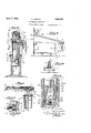
- Fig.l 1 is a side elevation of the machine constructed in accordance with my invention, showing the same in operative relation to the Work.
- Fig. 2 is a sectional View of the arm, showing the arrangement of the tool carriage thereon, the section being taken on the line 2-2 of Fig. 1.
- Fig. 3 is a sectional view of the support for the tool carrying arm, the section being taken on the line 3--3 of Fig. 1.
- Fig. 4 is a sectional View, on a large scale, of the carriage mounting on the arm.
- Fig. 5 is a vertical sectional view ofthe machine, the section being taken on the line 5-5 of Fig. 1.
- Fig. 6 is a ragmental vertical sectional view of the machine, the section being taken on the line 6--6 of Fig. 5.
- Fig. 7 is a iragmental view oi the bearing on the arm on which the sleeve of the carriage is guided.
- Fig. 8 is a sectional view of the hydraulic plunger and piston therein showing ⁇ the operating valve arrangement thereof.
- Fig. 9 is a side elevation of themachine as arianged in operative relation to a band saw
- Fig. 10 is a front view of the machine in operative relation to a joiner table or bench.
- the invention consists of an axially and rotatably adjustable standard 6, upon which is mounted an arm T, With freedom of axial and pivotal adjustments. 0n the arm is slidable a carriage 8, which carries a motor mounting 9.
- An electric motor 12 is adjustably held by said mounting and is vadapted to drive a desired tool, such as a circular saw 13. yThe aforementioned parts ofthe structure are, disposed to regulate the position of the electric motor 12, and of the tool thereon, relatively to a table or bench 14 upon which a piece of work 16 rests.
- the standard 6 is built on the hydraulic jack principle.
- a hydraulic cylinder 17 is fixedly supported on a base 18. The bottom of the cylinder 17 is closed so as to hold a fluid, such as oil or water therein.
- a plunger 18 is reciprocable in the cylinder 17.
- the plunger 18 is cylindrical and has diametrically opposed axial grooves 19 onrthe periphery thereof.
- a graduated ring 21 is disposed in a recess 22 in the top flange 23 at ⁇ the open end of the cylinder 18.
- the ring21 has an annular ange 24 thereon reduced in thickness, over which is secured aI retaining ring 26, so as to rotatablyvhold the ring 21 in place.
- keys 27 On the inner periphery of the ,ring 21 are formed keys 27 that extend into the 'grooves 19 so as to'operatively connect the plunger 18 with the graduated ring 21.
- the retainer ring 26 has a vmarker 28 thereon as shown in Fig. 3, which indicates on the graduations of the ring 21, the angular displacement of the plunger 18.
- the raising land lowering of. the plunger 18 is accomplished by reciprocation and pumping action of the piston 29 therein.
- the piston 29 cooperates with valves 31 and 32, whereby the flow of fluid is regulated from one side of the plunger bottom 33 to the other side thereof.
- the valve 31 is dis.
- a valve head 36 of said valve 31 has a valve stem 37 extending therefrom thru the aperture 34 and into the plunger 18.
- aperture 34 has a ⁇ spider structure therein
- a compression spring 40 On the stem 37 yis fixed a nut 39 and between the nut 39 and the top of the spider bearing 38 is disposed a compression spring 40, to urge the nut 39 upwardly thereby firmly seating the valve head 36 against the lower face of theplunger bottom 33 so as to normally close the aperature 33.
- the free end of the stem 37 extends into operative relation to the bottom of the piston 29.
- the piston 29 is closed at the bottom 41 thereof excepting an eccentrically located passage 42 therein.
- This passage 42 is adapted to be closed by a valve disc 43 lformed on the free end of a lever 44, which is vpivoted intermediate its ends in a bracket 46 fixed on the inner face of the plunger bottom 33..
- both the afore-described valves 31 and 32 have their actuating mechanisms disposed within the chamber 49 between the plunger bottom 33 and the piston bottom 41.
- the piston 29 In order to lower the plunger 18, the piston 29 is pressed downwardly so as to press' the valve stem 37 and the valve head 36 downwardly, thereby opening the valve 31. Inasmuch as the valve 32 is kept open at this time, by the bump 48 thereof, the fluid is permitted to escape from beneath the plunger 18 thru the aperture 34 and the passage 42, and flow into the plunger 18 and above the piston 29. The resulting reduction of fluid volume and pressure allows the plunger 18 to lower into the cylinder 17. The plunger 18 lowers by its own weight, during this operation, urging the fluid thru said open aperture 34 andv the passage 42. When the plunger 18 reaches the desired, lowered positlon, the piston 29 is raised and returned to its neutral position, as shown in Fig. 8.
- 'lhe operation oi' the pump piston 29 is achieved thru a connecting rod 54 connected at one'end thereof tothe piston 29.
- the other 'end ot the connecting rod 54 is pivoted on an eccentric crank 56 of a conical crank sleeve 57, the latter ⁇ fitting in a corresponding bearing 56 termed on the head 59 of the plunger 16.
- 'lhe sleeve 57 is rotatable on a shaft 61, entending across the plunger head 59.
- An end el the shaft 61 has a nut or head 62 thereoi outside ot the plunger head 59.
- the shalt 61 is a handle 63 to rotate the crank sleeve 57.
- the end of the connecting rod 54 which ⁇ is pivoted to the crank 56 has a curved bend 64 therein, as
- an arcuate wed e block section 64 is disposed in a slot 66 o the plunger 18, so as to be radially slidable in said slot 66.
- outer periphery oi the wedge 64 is a section oit a cylinder, the inner periphery thereof is an inclined surface, corresponding to a conical inner wall 67 oli' the piston 29.
- rlhe conical wall 67 tapers upwardly, consequently, il" the piston29 is raised sufficiently high to bring the wall 67 into engagement with the inclined surface of the wedge 64, the wedge 64 will be pressed radially outward, and thus jammed against the inner wall ol the cylinder 17, to lock the piston in this position.
- 'l ⁇ he wedge 64 is prevented from accidental sliding toward the cylinder wall by means of a spring ring 68 extending all laround the periphery or the plunger 18.
- the upper end of the rod 51 is Pivotally" connected to an auxiliary crank sha t 67 supported in a bearing in the plunger head 59, at a Vpoint below the crank lsleeve 57.
- a handle 71 on the outer end of the crank shaft 67 is rocked back and Jforth to operate the rod 51 and effect the step by step, gradual lowerinof the plunger 18.
- the plun er 18 may be raised by repeated pumping y the piston 29, and lowered either y depressing the piston 29, or by repeatedly depressing the rod 51 onto the valve disc 43. .lhe plunger 18 can be locked in position by raising the piston 29 sufficiently hi h to jam the. wedge into engagement with t e inner ⁇ periphery of the cylinder 17. The adjustment of the plunger 18 determines the height of the position of th parts supported on the plunger 18.
- a bearing box 72 in which is transversely secured a trunnion block 73 adapted to be moved around its pivots to various angular positions.
- a trunnion block 73 On the bottom side of the block 72 at each end ⁇ thereof, is formed atoothed segment 74, for engagement with a meshing gear 76.
- the gears 76 are fixed on a trans verse shaft 77, an end of which extends outis adapted toV be inserted into holes 81 in a wall of the bearingr box 72, thereby to lock they ears 7'6 against rotation and to hold the bloc t 73 in adJusted angular positions.
- the arm 7 is slidably disposed in the block 7 3. 0n each side of the arm 7 is a long, axially disposed key 82.
- the keys 82 are'slidable in keyways 83 in the block 72, whereby the arml 7 is held against rotation.
- the arm is pivotally elevated or lowered by the turning of the crank 77 and gears 74 to the desired degree, so as to hold the block 72 and the arm 7 therein, at the required angularity.
- the axial movement of the arm 7 is con" trolled by the use of a threaded bar-84 which extends throughout the hollow arm 7, and is journaled in the opposite ends of the arm 7.
- the bar 84 is supported in a threaded bracket 86, which latter is .fixed on the block 72 so as toextend into the interior of the arm 7
- An elongated slot 87 is cut in the wall ot the hollow arm 7 in registry with the bracket 86, so as to allow axial movement of the arm 1 y i
- the carriage 8 is constructed of a sliding the arm 7.
- In the three sides of each keyway 92 are formed parallel axial channels 93, one in each side.
- In each channel 93 are mounted rollers 94 to bear against the respective sides of the keys 82.
- the rollers 94 may be tightly ressed against the sides of the respective eys 82 by means of set screws 96 extending thru the ivall of the sliding sleeve 89.
- the rotary sleeve 91 is shorter than the sliding sleeve 89.
- On the outer periphery of the rotary sleeve 91 is fixed a toothed ring 97.
- On the outer periphery of the rotary sleeve 91 is a pivoted latch or paWl 98 for engagement with the teeth of the ring 97, to hold the rotary sleeve 91 in any adjusted position.
- the motor mounting 9 and the motor 12 may be held projecting in different angular positions from the arm 7. For instance, in Fig. 1 the motor is belowV the arm 7, and in Fig..9 the motor is securely held above the arm 7.
- a short handle 99 on the rotary sleeve. 91 facilitates the handling of the carriage.
- the mounting 9 is a universally adjustable joint so that the motor may be arrdnged in parallelism with the arm 7, or at an angle thereto in a parallel plane, or at an angle to the arm 7 1n a plane intersecting that of .the arm.
- a yoke 101 is secured by a vertical pivot or king-pin 102 to a depending portion 103 of the rotary sleeve 91. ⁇ Between the legsof the yoke 101 is pivoted a lug 104 which extends from the casing of the motor 12.-
- the mounting is kadjustable around the pin 102, and at right angles to said pin around the pivot of the lug 104.
- a coggd Wheel 10G on the portion 103 is detachably engaged by a pawlor latch 107 on the yoke 101 to tix the mounting in a certain adjusted position.
- the legs of the yoke 101 terminate in quadrants 108, which cooperate with latches 109 on the opposite sides of the lug 104, to hold the motor 12 against accidental movement around the pivot of the lug 104.
- the lug pivot comprises a pin 111 Iixed t'o the lug'and journaled in the legs of the yoke 101.
- a short handle 112 is provided on an end of the pin 111 to facilitate adjustment of the mounthe tool connected ⁇ to the lmotor 12 lis brought above a desired point of the bench justed by turnlng the handle 78 to the re-V Lacasse quired position. Thereafter the length of the arm 71s adjusted by rotating the handle 88. The carriage 8 is then slid and rotated to have the motor secured on the required side ofthe arm 7, whereupon the mounting 9 is adjusted to accurately center the tool on the work, both as to location, and as to direction of cut or other operation. In this manner the saw 13, for instance, may be held in position for cutting, or ripping operations. By adjusting the angularity of the mounting and the motor location, the same machine is ready to perform a miter cut.
- Fig. 10 the entire mechanism is shown in its lowered position so that the saw 13 of the machine is in alignment with a joiner 117- tables for the various operations may be arranged in a circle around the machine, if so desired, and the motor and the proper tool thereon can be readily brought around into alignment, selectively, with either table or Work, performing many various operations on wood Work with great efficiency, and economy.
- a vertically and rotatably adjustable support a tool supporting arm, means on the support to mount the arm thereon with freedom of axial and pivotal adjustment; a carriage on the arm adapted to be adjusted axially thereon and angularly therearound; and ⁇ a tool driving unit universally mounted on said carvriage'to hold the tool ⁇ connected thereto in registry yvith a piece of Work, in a position determined by the adjustments of the support of the arm, and of the carriage.
- a machine of the character described titi a support, a tool supporting arm adjustably mounted thereon a carriage on the arm, comprising a sliding sleeve on the arm,a sleeve rotatable on the sliding sleeve, andmeans to secure the rotatable sleeve on the sliding sleeve in any adjusted, angular position; and a tool driving unit mounted on the rotatable sleeve to hold and drive a tool in a position relative to a piece of work, determined by the adj ustments of said arm and said carriage.
- a machine ot the character described a support, a tool supporting arm adjustably mounted thereon, a carriage on the arm adapted to be adjusted axially and angularly thereon, a yoke depending Jfrom said carriage, being pivoted at right angles to the axis of the arm, a tool driving unit pivoted transversely in said yoke to drive and support a tool in operative position to a piece of work, in a position determined by the adjustment or the yoke in the carriage, and of the unit on the yoke; means to secure the yoke in adjusted position, and means to secure the unit in its adjusted position.
- a machine of the character described a support, a block transverselv pivoted on said support ⁇ ⁇ a hollow arm slidably held in said block, a threaded member havine: a crank handle on an end thereof and extending axially thru said hollow arm.
- said arm being adapted to be axially moved thru said block as the said member is rotated; an adjustable carriage on the arm, and a tool driving unit mounted on said carriage to drive a tool conneeted thereto, and to support the same in alignment with a piece ot work, as deter ⁇ mined by the adjustment of said arm, ot' said carriage, said carriage comprising a sliding sleeve on the arms, a sleeve rotatable on the sliding1 sleeve, and means to secure the rotatable sleeve to the sliding sleeve in anv adjusted angular position, said driving unit beinamounted on the rotary sleeve.
- a support in a machine of the character described a support, a block transversely pivoted on said support, a hollow arm slidably held in said block, a threaded member having a crank handle on an end thereof and extending axia1- ly thru said hollow arm, a fixed internally threaded bracket on said block to threadedly engage said member, said arm being adapted to be axially moved thru said block as the saidmember is rotated; an adjustable carriage on the arm, a tool driving unit mounted on said carriage to drive a.
- means to mount the driving unit on the carriage comprising a yoke depending from said carriage being pivoted at' right angles to the axis of the arm, said driving unit being pivoted transversely in said yoke,
Description
April 5, 1932. 1 wlEDEN WOODWORKING MACHINE Filed Feb. 8. 1930 2 Sheets-Sheet l INVENTOR, M//EpE/v pl'il 5, W|EDEN WOODWORKING MACHINE Filed Feb. 8. 19250V 2 Sheets-Sheet 2 Patented Apr. s,
PATEN'n OFFICE LQ'UIS-WIEDEN, 0F LVEBMORE, CALIFORNIA WOOD'WORKING MACHINE Application led February 8, 1930. Serial vNo. 426,859.
This invention relates to universal woodlvvorhing machines.
llt is the primary object ci the invention to provide a wood-working machine which is t adapted to support atool in various operating positions so that dierent operations and types ot cuts may be performed by the same machine, with great facility and ease.
llarticularly it is anobj ect oi the invention ltito provide a universally adjustable standard tor wood-Working tools, wherein the prime mover oi the tool, such as' an electric motor, is adjustably mounted on a4 carriage, which carriage is in turn, axially and rotat ably adjustable on a comparatively long roc'lr-` ing arm, the protrudin length and angular position oi said arm being readily and positively determined in an arm support, by axial displacementmnd by angular elevation therelill oi; the support itselt is rotatable and is adapted to be raised and lowered in a iixed standard; in connection with all the adjustable joints, means is provided to lock the m respective joints and the parts connected ll thereby, in the adjusted positions thereof.
illy adjusting the positions oi the carriage, the arm, andai the support, the tool may be held in a desired osition in relation to a work table or bene to perform the required opl@ erations on the worlr, such as cutting, ripping, ruiter cuts, band-saw cuts, or joining and the lilre. Y A@mother object oi the invention is the provision ol a hydraulically raised and lowered tool support :tor machines loi the character use and general eiliciency.
ln 'this specification and the annexed drawings, 'the invention is illustrated in the iorm considered to be the best, but it is to be understood that the invention is not limited to such U torna, because it may be embodied in other '.torms; and it is also to be understood that in and by the claims following the description, it is desired to cover the invention in whatsoever form it may be embodied.
The invention is clearly illustrated in the accompanying drawings wherein Fig.l 1 is a side elevation of the machine constructed in accordance with my invention, showing the same in operative relation to the Work. Fig. 2 is a sectional View of the arm, showing the arrangement of the tool carriage thereon, the section being taken on the line 2-2 of Fig. 1.
Fig. 3 is a sectional view of the support for the tool carrying arm, the section being taken on the line 3--3 of Fig. 1.
Fig. 4 is a sectional View, on a large scale, of the carriage mounting on the arm.
Fig. 5 is a vertical sectional view ofthe machine, the section being taken on the line 5-5 of Fig. 1.
Fig. 6 is a ragmental vertical sectional view of the machine, the section being taken on the line 6--6 of Fig. 5.
Fig. 7 is a iragmental view oi the bearing on the arm on which the sleeve of the carriage is guided.
Fig. 8 is a sectional view of the hydraulic plunger and piston therein showing` the operating valve arrangement thereof. j
Fig. 9 is a side elevation of themachine as arianged in operative relation to a band saw; an
Fig. 10 is a front view of the machine in operative relation to a joiner table or bench.
ln its general organization the invention consists of an axially and rotatably adjustable standard 6, upon which is mounted an arm T, With freedom of axial and pivotal adjustments. 0n the arm is slidable a carriage 8, which carries a motor mounting 9. An electric motor 12 is adjustably held by said mounting and is vadapted to drive a desired tool, such as a circular saw 13. yThe aforementioned parts ofthe structure are, disposed to regulate the position of the electric motor 12, and of the tool thereon, relatively to a table or bench 14 upon which a piece of work 16 rests.
The standard 6 is built on the hydraulic jack principle. A hydraulic cylinder 17 is fixedly supported on a base 18. The bottom of the cylinder 17 is closed so as to hold a fluid, such as oil or water therein.
A plunger 18 is reciprocable in the cylinder 17. The plunger 18 is cylindrical and has diametrically opposed axial grooves 19 onrthe periphery thereof. A graduated ring 21 is disposed in a recess 22 in the top flange 23 at` the open end of the cylinder 18. The ring21 has an annular ange 24 thereon reduced in thickness, over which is secured aI retaining ring 26, so as to rotatablyvhold the ring 21 in place. On the inner periphery of the ,ring 21 are formed keys 27 that extend into the 'grooves 19 so as to'operatively connect the plunger 18 with the graduated ring 21. The retainer ring 26 has a vmarker 28 thereon as shown in Fig. 3, which indicates on the graduations of the ring 21, the angular displacement of the plunger 18.
The movement ofthe plunger 18 into and out of the cylinder 1 7 is accomplished bythe use of a pump piston 29 adjacent vthe lower closed end of the plunger 18, as clearly shown in Fig. 8.
The raising land lowering of. the plunger 18 is accomplished by reciprocation and pumping action of the piston 29 therein. The piston 29 cooperates with valves 31 and 32, whereby the flow of fluid is regulated from one side of the plunger bottom 33 to the other side thereof. The valve 31 is dis.
posed in a central aperture 34 in the bottom 33. A valve head 36 of said valve 31 has a valve stem 37 extending therefrom thru the aperture 34 and into the plunger 18. The
the hub 38 of which is the guiding bearing of the stem 37. On the stem 37 yis fixed a nut 39 and between the nut 39 and the top of the spider bearing 38 is disposed a compression spring 40, to urge the nut 39 upwardly thereby firmly seating the valve head 36 against the lower face of theplunger bottom 33 so as to normally close the aperature 33. The free end of the stem 37 extends into operative relation to the bottom of the piston 29.
The piston 29 is closed at the bottom 41 thereof excepting an eccentrically located passage 42 therein. This passage 42 is adapted to be closed by a valve disc 43 lformed on the free end of a lever 44, which is vpivoted intermediate its ends in a bracket 46 fixed on the inner face of the plunger bottom 33..
Against the other end of the lever 44 bears a coil s ring 47 which is disposed between the sai second end of the lever 44 and the piston bottom 41. The lever 44 is formed with a bump or protuberance 48 adjacent the valve disc 43, against which the piston bottom 41 abuts, whereby the valve disc 43 is normally held spaced from the passage 42, allowing the passing of the fluid therethru. It is to be noted that both the afore-described valves 31 and 32 have their actuating mechanisms disposed within the chamber 49 between the plunger bottom 33 and the piston bottom 41.
In operation there is iuid both in the cylinder 17 and within the hollow plunger 19. In order to raise the plunger 18, the
builds up a pressure in the chamber 49 which 'l forces the valve head 36 away from the plunger bottom 33 and urges the fluid under pressure, thru the aperture 34 into the space beneath the plunger bottom 33. The increase of iiuid volume and pressure in the cylinder 17 below the plunger 18, raises the plunger 18. When the fluid pressures in the chamber 49 and belowthe plunger bottom 33 are equalized, the spring 40 brings the valve head 36 into engagement with the plunger bottom 33, thereby. closing the valve 31. The aforedescribed pumping operation is repeated until the plunger 18 is raised to the -desired height. 'lhe piston 29 must be so operated that its downward stroke ends when the `piston bottom 41 abuts against the top of the valve stem 37, and its upward stroke is terminated yafter the valve 32 is closed.
In order to lower the plunger 18, the piston 29 is pressed downwardly so as to press' the valve stem 37 and the valve head 36 downwardly, thereby opening the valve 31. Inasmuch as the valve 32 is kept open at this time, by the bump 48 thereof, the fluid is permitted to escape from beneath the plunger 18 thru the aperture 34 and the passage 42, and flow into the plunger 18 and above the piston 29. The resulting reduction of fluid volume and pressure allows the plunger 18 to lower into the cylinder 17. The plunger 18 lowers by its own weight, during this operation, urging the fluid thru said open aperture 34 andv the passage 42. When the plunger 18 reaches the desired, lowered positlon, the piston 29 is raised and returned to its neutral position, as shown in Fig. 8.
In some instances it is required to lower the plunger 18, very gradually and accurately. This adjustment is to be eii'ected step by step with very short drops. To accomplish this adjustment the lever 44 is so formed as to abut at a point 50, against the top of the nut 39, so that if the valve disc 43 is urged downwardly beyond the neutral position shown in Fig. 8, the lever engages the nut 39 to move liltl lill the stem 37 downwardly, whereby the valve .Slis opened permitting the escapement of huid trom beneath the plun er bottom 33. lhe valve 81 is opened only or short dura.- tions and then re eased, causing a comparatively small drop of the plunger 18 in the .cylinder 17. `This short valve opening is performed by moving a rod 51 against the valve disc 43 at will. The rod 51 is guided in an aperture 52 thru the piston 29 and is normally urged away from the valve disc 48 by means `ol a compression spring 58 disposed between the top of the piston 29 and a hired washer 54' on the rod 51, above the top ot the piston 29. The repeated lowering and raising ol the rod 51 into and out of engagement with the valve disc 43, effects the lowering ol." the plunger 18 step by step, ofany short duration desired.
'lhe operation oi' the pump piston 29 is achieved thru a connecting rod 54 connected at one'end thereof tothe piston 29. The other 'end ot the connecting rod 54 is pivoted on an eccentric crank 56 of a conical crank sleeve 57, the latter `fitting in a corresponding bearing 56 termed on the head 59 of the plunger 16. 'lhe sleeve 57 is rotatable on a shaft 61, entending across the plunger head 59. An end el the shaft 61 has a nut or head 62 thereoi outside ot the plunger head 59. On the other end ol" the shalt 61 is a handle 63 to rotate the crank sleeve 57. The end of the connecting rod 54 which `is pivoted to the crank 56, has a curved bend 64 therein, as
r shown in lili 6, to allow the swinging movernent thereopast the shaft 61. A coil spring 66 around the shaft 61 within the plunger head 59, limits vthe movement of the sleeve into the head 59.
lllhen the handle 63 is rotated in clockwise direction viewing Fig. l, the connecting rod 54 and the piston 29 are moved downwardly, while the rotation ofthe handle 63 in the opposite direction raises the piston 29. ln order to lock the piston 29 in an uppermost position, an arcuate wed e block section 64 is disposed in a slot 66 o the plunger 18, so as to be radially slidable in said slot 66. rlhe outer periphery oi the wedge 64 is a section oit a cylinder, the inner periphery thereof is an inclined surface, corresponding to a conical inner wall 67 oli' the piston 29. rlhe conical wall 67 tapers upwardly, consequently, il" the piston29 is raised sufficiently high to bring the wall 67 into engagement with the inclined surface of the wedge 64, the wedge 64 will be pressed radially outward, and thus jammed against the inner wall ol the cylinder 17, to lock the piston in this position. 'l`he wedge 64 is prevented from accidental sliding toward the cylinder wall by means of a spring ring 68 extending all laround the periphery or the plunger 18. ln
normal operation the piston 29 is not pulled upwardly so far as to engage the wedge 64,
vunless the locking The upper end of the rod 51 is Pivotally" connected to an auxiliary crank sha t 67 supported in a bearing in the plunger head 59, at a Vpoint below the crank lsleeve 57. A handle 71 on the outer end of the crank shaft 67 is rocked back and Jforth to operate the rod 51 and effect the step by step, gradual lowerinof the plunger 18.
y the afore-described instrumentalities the plun er 18 may be raised by repeated pumping y the piston 29, and lowered either y depressing the piston 29, or by repeatedly depressing the rod 51 onto the valve disc 43. .lhe plunger 18 can be locked in position by raising the piston 29 sufficiently hi h to jam the. wedge into engagement with t e inner `periphery of the cylinder 17. The adjustment of the plunger 18 determines the height of the position of th parts supported on the plunger 18.
On the lunger head 59 is xedly secured a bearing box 72 in which is transversely secured a trunnion block 73 adapted to be moved around its pivots to various angular positions. On the bottom side of the block 72 at each end` thereof, is formed atoothed segment 74, for engagement with a meshing gear 76. The gears 76 are fixed on a trans verse shaft 77, an end of which extends outis adapted toV be inserted into holes 81 in a wall of the bearingr box 72, thereby to lock they ears 7'6 against rotation and to hold the bloc t 73 in adJusted angular positions.
The arm 7 is slidably disposed in the block 7 3. 0n each side of the arm 7 is a long, axially disposed key 82. The keys 82 are'slidable in keyways 83 in the block 72, whereby the arml 7 is held against rotation. The arm is pivotally elevated or lowered by the turning of the crank 77 and gears 74 to the desired degree, so as to hold the block 72 and the arm 7 therein, at the required angularity..
The axial movement of the arm 7 is con" trolled by the use of a threaded bar-84 which extends throughout the hollow arm 7, and is journaled in the opposite ends of the arm 7. The bar 84 is supported in a threaded bracket 86, which latter is .fixed on the block 72 so as toextend into the interior of the arm 7 An elongated slot 87 is cut in the wall ot the hollow arm 7 in registry with the bracket 86, so as to allow axial movement of the arm 1 y i The carriage 8 is constructed of a sliding the arm 7. In the three sides of each keyway 92 are formed parallel axial channels 93, one in each side. In each channel 93 are mounted rollers 94 to bear against the respective sides of the keys 82. The rollers 94 may be tightly ressed against the sides of the respective eys 82 by means of set screws 96 extending thru the ivall of the sliding sleeve 89.
The rotary sleeve 91 is shorter than the sliding sleeve 89. On the outer periphery of the rotary sleeve 91 is fixed a toothed ring 97. On the outer periphery of the rotary sleeve 91 is a pivoted latch or paWl 98 for engagement with the teeth of the ring 97, to hold the rotary sleeve 91 in any adjusted position. By rotating the sleeve 91 the motor mounting 9 and the motor 12 may be held projecting in different angular positions from the arm 7. For instance, in Fig. 1 the motor is belowV the arm 7, and in Fig..9 the motor is securely held above the arm 7. A short handle 99 on the rotary sleeve. 91 facilitates the handling of the carriage.
The mounting 9 is a universally adjustable joint so that the motor may be arrdnged in parallelism with the arm 7, or at an angle thereto in a parallel plane, or at an angle to the arm 7 1n a plane intersecting that of .the arm.
.A yoke 101 is secured by a vertical pivot or king-pin 102 to a depending portion 103 of the rotary sleeve 91.` Between the legsof the yoke 101 is pivoted a lug 104 which extends from the casing of the motor 12.-
Thus the mounting is kadjustable around the pin 102, and at right angles to said pin around the pivot of the lug 104. A coggd Wheel 10G on the portion 103 is detachably engaged by a pawlor latch 107 on the yoke 101 to tix the mounting in a certain adjusted position. The legs of the yoke 101 terminate in quadrants 108, which cooperate with latches 109 on the opposite sides of the lug 104, to hold the motor 12 against accidental movement around the pivot of the lug 104. The lug pivot comprises a pin 111 Iixed t'o the lug'and journaled in the legs of the yoke 101. A short handle 112 is provided on an end of the pin 111 to facilitate adjustment of the mounthe tool connected `to the lmotor 12 lis brought above a desired point of the bench justed by turnlng the handle 78 to the re-V Lacasse quired position. Thereafter the length of the arm 71s adjusted by rotating the handle 88. The carriage 8 is then slid and rotated to have the motor secured on the required side ofthe arm 7, whereupon the mounting 9 is adjusted to accurately center the tool on the work, both as to location, and as to direction of cut or other operation. In this manner the saw 13, for instance, may be held in position for cutting, or ripping operations. By adjusting the angularity of the mounting and the motor location, the same machine is ready to perform a miter cut. This universal arrangement allows the same motor, and in m'any 1nstances, the same saw to be used for nearly all the operations commonly performed by a saw on woodwg In Fig. 9 the motor 12 is disposed above the arm 7, and the arm 7 is elevated to a highermost position. The plunger 18 is also raised to the maximum height of operation. Thus space is left between the table 14 and the motor 12 to allow the placing of a bandsaw guide support 115 and a Work table 116 below the end ofv the arm 7. A band-saw 117 is connected to the motor 12 in the usual manner, and is aligned accurately to perform all the operations on a-Work that is to be performed by a band-saw.
In Fig. 10, the entire mechanism is shown in its lowered position so that the saw 13 of the machine is in alignment with a joiner 117- tables for the various operations may be arranged in a circle around the machine, if so desired, and the motor and the proper tool thereon can be readily brought around into alignment, selectively, with either table or Work, performing many various operations on wood Work with great efficiency, and economy.
Having thus described this invention, what I claim and desire to secure by Letters Patent is:l v
1. In a machine of the character described a vertically and rotatably adjustable support, a tool supporting arm, means on the support to mount the arm thereon with freedom of axial and pivotal adjustment; a carriage on the arm adapted to be adjusted axially thereon and angularly therearound; and `a tool driving unit universally mounted on said carvriage'to hold the tool` connected thereto in registry yvith a piece of Work, in a position determined by the adjustments of the support of the arm, and of the carriage.
2.111 a machine of the character described titi a support, a tool supporting arm adjustably mounted thereon a carriage on the arm, comprising a sliding sleeve on the arm,a sleeve rotatable on the sliding sleeve, andmeans to secure the rotatable sleeve on the sliding sleeve in any adjusted, angular position; and a tool driving unit mounted on the rotatable sleeve to hold and drive a tool in a position relative to a piece of work, determined by the adj ustments of said arm and said carriage.
3. lua machine of the character described a support, a block transversely pivoted on said support, a hollow arm slidably held in said block, a threaded member having a crank handle on an end thereot1 and extending' axially thru said hollow arm, a fixed internally threaded bracket on said block to threadedly engage said member, said arm being adapted to be axially moved thru said block as the said member is rotated; an adjustable carriage on the arm, and a tool driving unit mounted on said carriage to drive a tool connected thereto, and to support the same in alignment with a piece of work, as determined by the adjustmentpt said arm, and of said carriage.
d. ln a machine ot the character described a support, a tool supporting arm adjustably mounted thereon, a carriage on the arm adapted to be adjusted axially and angularly thereon, a yoke depending Jfrom said carriage, being pivoted at right angles to the axis of the arm, a tool driving unit pivoted transversely in said yoke to drive and support a tool in operative position to a piece of work, in a position determined by the adjustment or the yoke in the carriage, and of the unit on the yoke; means to secure the yoke in adjusted position, and means to secure the unit in its adjusted position. i
t?. iin a machine of the character described a support, a block transverselv pivoted on said support` `a hollow arm slidably held in said block, a threaded member havine: a crank handle on an end thereof and extending axially thru said hollow arm. a fixed internally threaded bracket on said block to threadedlv engage said member` said arm being adapted to be axially moved thru said block as the said member is rotated; an adjustable carriage on the arm, and a tool driving unit mounted on said carriage to drive a tool conneeted thereto, and to support the same in alignment with a piece ot work, as deter` mined by the adjustment of said arm, ot' said carriage, said carriage comprising a sliding sleeve on the arms, a sleeve rotatable on the sliding1 sleeve, and means to secure the rotatable sleeve to the sliding sleeve in anv adjusted angular position, said driving unit beinamounted on the rotary sleeve.
d. in a machine of the character described a support, a block transversely pivoted on said support, a hollow arm slidably held in said block, a threaded member having a crank handle on an end thereof and extending axia1- ly thru said hollow arm, a fixed internally threaded bracket on said block to threadedly engage said member, said arm being adapted to be axially moved thru said block as the saidmember is rotated; an adjustable carriage on the arm, a tool driving unit mounted on said carriage to drive a. tool connected thereto, and to support the same in alignmentjvith a piece of work, as determined byy the adjustment of said arm, and of said carriag'e; means to mount the driving unit on the carriage comprising a yoke depending from said carriage being pivoted at' right angles to the axis of the arm, said driving unit being pivoted transversely in said yoke,
means to secure the yoke in position, and4v means to tix the driving unit in adjusted position.l
ln testimony whereof l have hereunto set my hand at Livermore, California, this 13th day of December, 1929.
LOUIS WIEDEN.
Priority Applications (1)
| Application Number | Priority Date | Filing Date | Title |
|---|---|---|---|
| US426859A US1852387A (en) | 1930-02-08 | 1930-02-08 | Woodworking machine |
Applications Claiming Priority (1)
| Application Number | Priority Date | Filing Date | Title |
|---|---|---|---|
| US426859A US1852387A (en) | 1930-02-08 | 1930-02-08 | Woodworking machine |
Publications (1)
| Publication Number | Publication Date |
|---|---|
| US1852387A true US1852387A (en) | 1932-04-05 |
Family
ID=23692501
Family Applications (1)
| Application Number | Title | Priority Date | Filing Date |
|---|---|---|---|
| US426859A Expired - Lifetime US1852387A (en) | 1930-02-08 | 1930-02-08 | Woodworking machine |
Country Status (1)
| Country | Link |
|---|---|
| US (1) | US1852387A (en) |
Cited By (17)
| Publication number | Priority date | Publication date | Assignee | Title |
|---|---|---|---|---|
| US2471014A (en) * | 1943-09-21 | 1949-05-24 | Jr Henry L Trebert | Universal woodworking machine table |
| US2495438A (en) * | 1946-05-29 | 1950-01-24 | Bentley Weldery Inc | Work manipulator |
| US2556137A (en) * | 1946-12-11 | 1951-06-05 | Porter Cable Machine Co | Radial arm type sawing device |
| US2584863A (en) * | 1946-11-26 | 1952-02-05 | Gesner Carleton Peck | Radial saw |
| US2619995A (en) * | 1948-05-10 | 1952-12-02 | Russell R Gordon | Rotary saw apparatus having adjustable saw guide |
| US2722952A (en) * | 1951-04-06 | 1955-11-08 | Walt Inc De | Jointed radial arm mounting for cutting tool |
| US2835285A (en) * | 1955-06-06 | 1958-05-20 | Wallace W Gardner | Radial arm saw |
| US2852050A (en) * | 1955-04-25 | 1958-09-16 | Bevan Graham Horstmann | Universal woodworking machine |
| US2987085A (en) * | 1958-08-01 | 1961-06-06 | Burke E Porter Machinery Co | Automatic sequencing wood saw and clamp |
| US3092154A (en) * | 1960-03-28 | 1963-06-04 | Portable Electric Tools Inc | Radial saw adjustment means |
| US3295568A (en) * | 1964-09-17 | 1967-01-03 | Walt Inc De | Uni-directional indexing means for power-operated machine |
| US4354798A (en) * | 1979-04-23 | 1982-10-19 | Bekaert Engineering | Rotary tool positioning unit for a woodworking machine |
| US6257221B1 (en) * | 1998-10-02 | 2001-07-10 | Shouichi Shibuya | Cutting machine |
| US20060042442A1 (en) * | 2004-09-02 | 2006-03-02 | Shigeharu Ushiwata | Miter saw |
| US20060156888A1 (en) * | 2005-01-20 | 2006-07-20 | Shigeharu Ushiwata | Miter saw |
| US20060236834A1 (en) * | 2005-04-21 | 2006-10-26 | Nicholas Ange | Combination radial and miter saw |
| US20140251106A1 (en) * | 2013-03-08 | 2014-09-11 | Black & Decker Inc. | Chop saw with improved storage mode |
-
1930
- 1930-02-08 US US426859A patent/US1852387A/en not_active Expired - Lifetime
Cited By (23)
| Publication number | Priority date | Publication date | Assignee | Title |
|---|---|---|---|---|
| US2471014A (en) * | 1943-09-21 | 1949-05-24 | Jr Henry L Trebert | Universal woodworking machine table |
| US2495438A (en) * | 1946-05-29 | 1950-01-24 | Bentley Weldery Inc | Work manipulator |
| US2584863A (en) * | 1946-11-26 | 1952-02-05 | Gesner Carleton Peck | Radial saw |
| US2556137A (en) * | 1946-12-11 | 1951-06-05 | Porter Cable Machine Co | Radial arm type sawing device |
| US2619995A (en) * | 1948-05-10 | 1952-12-02 | Russell R Gordon | Rotary saw apparatus having adjustable saw guide |
| US2722952A (en) * | 1951-04-06 | 1955-11-08 | Walt Inc De | Jointed radial arm mounting for cutting tool |
| US2852050A (en) * | 1955-04-25 | 1958-09-16 | Bevan Graham Horstmann | Universal woodworking machine |
| US2835285A (en) * | 1955-06-06 | 1958-05-20 | Wallace W Gardner | Radial arm saw |
| US2987085A (en) * | 1958-08-01 | 1961-06-06 | Burke E Porter Machinery Co | Automatic sequencing wood saw and clamp |
| US3092154A (en) * | 1960-03-28 | 1963-06-04 | Portable Electric Tools Inc | Radial saw adjustment means |
| US3295568A (en) * | 1964-09-17 | 1967-01-03 | Walt Inc De | Uni-directional indexing means for power-operated machine |
| US4354798A (en) * | 1979-04-23 | 1982-10-19 | Bekaert Engineering | Rotary tool positioning unit for a woodworking machine |
| US6257221B1 (en) * | 1998-10-02 | 2001-07-10 | Shouichi Shibuya | Cutting machine |
| US20060042442A1 (en) * | 2004-09-02 | 2006-03-02 | Shigeharu Ushiwata | Miter saw |
| US7997177B2 (en) * | 2004-09-02 | 2011-08-16 | Hitachi Koki Co., Ltd. | Miter saw |
| US8561513B2 (en) | 2004-09-02 | 2013-10-22 | Hitachi Koki Co., Ltd. | Miter saw |
| US20060156888A1 (en) * | 2005-01-20 | 2006-07-20 | Shigeharu Ushiwata | Miter saw |
| US20110041665A1 (en) * | 2005-01-20 | 2011-02-24 | Shigeharu Ushiwata | Miter Saw |
| US7905167B2 (en) * | 2005-01-20 | 2011-03-15 | Hitachi Koki Co., Ltd. | Miter saw |
| US8161859B2 (en) * | 2005-01-20 | 2012-04-24 | Hitachi Koki Co., Ltd. | Miter saw |
| US20060236834A1 (en) * | 2005-04-21 | 2006-10-26 | Nicholas Ange | Combination radial and miter saw |
| US20140251106A1 (en) * | 2013-03-08 | 2014-09-11 | Black & Decker Inc. | Chop saw with improved storage mode |
| US9283628B2 (en) * | 2013-03-08 | 2016-03-15 | Black & Decker Inc. | Chop saw with improved storage mode |
Similar Documents
| Publication | Publication Date | Title |
|---|---|---|
| US1852387A (en) | Woodworking machine | |
| US2038810A (en) | Circular-saw machine | |
| US1816829A (en) | Hydraulic upright drill | |
| US3667305A (en) | Machine tool having a rotary worktable | |
| US3011533A (en) | Combination power tool with adjustable tool spindle | |
| US3621829A (en) | Masonry cutting apparatus | |
| US2254046A (en) | Cutting machine | |
| GB1595641A (en) | Spindle operating assembly for a machine tool | |
| US2364065A (en) | Gear shaping machine | |
| US2357790A (en) | Hydraulic duplicating planer attachment | |
| US2572756A (en) | Combined machine tool | |
| US2007827A (en) | Milling machine | |
| US1942414A (en) | Actuating means for machine tools | |
| US3822512A (en) | Automatic surface grinder | |
| US2050127A (en) | Tracer controlled cam cutting machine | |
| US3105413A (en) | Machine tool for machining cylindrical and conical bores in workpieces | |
| US2873557A (en) | Grinding machine | |
| US2243303A (en) | Sawing machine | |
| US2101787A (en) | Grinding machine | |
| US2477490A (en) | Form tool planer | |
| US1909767A (en) | Machine tool | |
| US1242775A (en) | Milling-machine. | |
| US2333169A (en) | Filing machine | |
| US2105130A (en) | Pouncing machine | |
| DE850860C (en) | Machine for processing, especially grinding of pump blades and the like. like |