US1852377A - Impedance bond for track circuits - Google Patents
Impedance bond for track circuits Download PDFInfo
- Publication number
- US1852377A US1852377A US509162A US50916231A US1852377A US 1852377 A US1852377 A US 1852377A US 509162 A US509162 A US 509162A US 50916231 A US50916231 A US 50916231A US 1852377 A US1852377 A US 1852377A
- Authority
- US
- United States
- Prior art keywords
- track
- current
- block
- bond
- impedance
- Prior art date
- Legal status (The legal status is an assumption and is not a legal conclusion. Google has not performed a legal analysis and makes no representation as to the accuracy of the status listed.)
- Expired - Lifetime
Links
Images
Classifications
-
- B—PERFORMING OPERATIONS; TRANSPORTING
- B61—RAILWAYS
- B61L—GUIDING RAILWAY TRAFFIC; ENSURING THE SAFETY OF RAILWAY TRAFFIC
- B61L23/00—Control, warning, or like safety means along the route or between vehicles or vehicle trains
- B61L23/08—Control, warning, or like safety means along the route or between vehicles or vehicle trains for controlling traffic in one direction only
- B61L23/14—Control, warning, or like safety means along the route or between vehicles or vehicle trains for controlling traffic in one direction only automatically operated
- B61L23/16—Track circuits specially adapted for section blocking
- B61L23/166—Track circuits specially adapted for section blocking using alternating current
Definitions
- This invention relates to impedance bonds, and more particularly to means for supplying the magnetizing current to such impedance bonds.
- An impedance bond is a device for connecting two adjacent insulated track circuits for the flow of propulsion current.
- impedance bonds In applying impedance bonds to connect the ends of adjacent track circuits of a railway system of the propulsion type, it has been found that the core structure for these bonds must be rather large to provide sufficient impedance when using a comparatively small number of turns of wire thereon and further to avoid saturation of the core, due to the propulsion current flowing from the track rails of one track section to the track rails of another track section, when the propulsion current is unbalanced in the two rails. Furthermore, these impedance bonds must have a rather high impedance to produce the desired counter electro-inotive force for the signal frequency.
- the magnetizing current to produce this counter electro-motive force has heretofore been drawn from the track circuit itself, and has therefore robbed the track relay, connected across the track rails at the end of the track circuit, of a large portion of the current which could otherwise have been used for energizing the track relay.
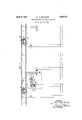
- the track rails 1 have been shown divided by insulating joints 2 into blocks, of which the block I and the adjacent ends of blocks H and J only have been illustrated.
- a track relay TR which is normally fed by a track transformer T connected across the rails at the exit end of such block, the normal direction of trafiic being from left to right as indicated by the arrow. Since the apparatus at the entrance end of each block is the same, such apparatus has not been shown for the block J.
- the track relay TR is preferably an alternating current relay of the three-position induction type, although a single phase alternating current relay may be used, if deslred, of which the local winding is connected across the transmission line TL, which supplies the signalling current, and therefore als g supplies energy to the track transformer i
- the impedance bond EB in the particular embodiment of the invention illustrated, comprises an inductance 11 Wound on a suitable laminated core, preferably including an air gap, and a similar inductance 12 also including a suitable laminated core preferably having an air gap therein, these two inductances having the midpoint of their windings connected together as by a wire 13. Their air gaps are used to prevent saturation of the core by flux due to the propulsion current.
- the propulsion current is usually direct current it may also be alternating current preferably of low frequency. From this structure it is ap parent that the flow of current equally divided between the two rails of the track Will produce no magnetism in the cores of the inductances 11 and 12, but that the flow of alternating signalling current tending to flow from one track rail to the other of the same block is restricted to the magnetizing current required to build up the necessary counter electromotive force and it follows that the voltage induced in 12 is substantially equal and opposite to the track circuit alternating current voltage.
- this inductance 11 of the impedance bond EB is not so important since it is located near the track transformer and can readily be supplied with the necessary magnetizing current.
- this inductance has a second winding 18 inductively associated therewith, which for convenience is called the primary winding, and this winding 18 is included in the plate circuit including the plate P of an amplifier A, the plate potential being derived from the eliminator, conventionally shown by dotted rectangle E, and including a transformer 20 and two rectifiers 21 and 22, it being, of course understood that any other suitable source of direct current potential may be employed, if desired.
- the current flowing in this plate circuit is derived from the secondary winding of "the transformer 20 through one or the other of the rectifiers 21 and 22, depending upon whether a positive or negative wave of alternating current is flowing in the primary winding of this transformer 20.
- This plate circuit comprises the wire 23, orimary winding 18 of the inductance 12, wire 24:, plate P of the amplifier A, to the filament F of this amplifier, and through wire 25 back to the midpoint of the secondary winding of the transformer 20.
- the pulsating current flowing in this plate circuit is by reason of the potential of the grid G of a frequency and phase relation to induce an alternating potential in the inductance 12 corresponding to the voltage across the track relay TR, this current resulting in response to the potential applied to the grid G of the amplifier A.
- the grid potential is preferably pr0portional to the voltage of the track circuit, and for this reason the grid is connected to an intermediate point of a resistance connected across the track relay TR.
- This interme diate point is preferably adjustable so that this resistance unit with its adjustable tap comprises a potentiometer AI.
- the filament or heater F is energized from a filament battery 30, or from any other suitable source of direct or alternating current.
- the apparatus of the present invention functions in the following manner:
- the alternating signal potential across the track relay TR, a definite fraction thereof, is applied to the grid G of the amplifier A, so that a pulsating current is produced in the plate circuit including the plate P.
- This pulsating current is of the proper frequency and phase relation to supply the magnetizing current to the primary winding 18 of the in ductance 12.
- the amplifier shown is connected in a regenerative circuit, in that the current applied for exciting the core of the inductance 12 results in a potential which is applied across the in-put or grid connection of the amplifier A.
- the various constants are so selected that this regenerative efiect is insufiicient to maintain oscillation and maintain the track relay TR energized, this especially being true if there is a train in the track circuit of the block I.
- What I claim as new is 1.
- railway track rails divided into blocks by insulating joints, impedance bonds connecting said blocks to permit propulsion current to flow from block to block, a track circuit for each block including a track relay and a source of alternating current, and means exterior of the track relay energizing circuit for supplying magnetizing current to the bond at one end of said track circuit to induce an alternating current voltage therein in phase opposition to the track circuit alternating current potential at said bond.
- An impedance bond for permitting the flow of propulsion current from lJlOClCtO block comprising, two inductances each having a middle tap and each connected across the travel; rails of one block of two adjacent blocks insulated from each other and with their taps connected together, a vacuum type amplifier having a filament, a grid and a plate, a source of current for energizing said filament, a plate circuit including a source of current said filament and said plate in series, and means for impressing the potential existing across the track rails between said filament and grid and for inductively connecting said plate circuit to one of said bonds.
- An impedance bond comprising, two inductances each having a middle tap each connected across the track rails of one block of two adjacent blocks insulated from each other and with their taps connected together, a vacuum type amplifier having a filament,a grid and a plate, a source of current for energizing said filament, a plate circuit including a source of current said filament and said plate in series, means tor impressing the potential existing across the track rails between said filament and grid and :lor inductively connecting said plate circuit to one oi said bonds, and a variable impedance included in series with said grid.
- An impedance bond for permitting the flow of propulsion current from block to block but restricting the flow of alternating current within a bloclt comprising, two inductances each having a middle tap each connected across the tracl-r rails of one block of two adjacent blocl-cs insulated from each other and with these taps connected together, a vacuum type amplifier having a tilzu'nent, a grid and plate, a source of current for energizing said filament, a plate circuit including the direct current outuut leads oi an alternating current ted eliminator said filament and said plate in series, means for impressin the potential existing across the track raiis between said filament and grid and tor inductively connecting said plate circuit to one of said bonds.
- An impedance bond comprising, two i11- ductances each having a middle tap each connected across the track rails of one block of two adjacent blocks insulated from each other and with their taps connected together, and adjustable means for supplying alternating magnetizing current to one of said bonds to induce therein an alternating current potential of a predetermined value, fre quency and phase relation.
- An impedance bond for permitting the flow of propulsion current from block to block comprising, two inductances each having a middle tap each connected across the track rails of one block of two adjacent blocks insulated from each other and with these taps connected together; a vacuum type amplifier having a filament; a grid and a plate; a source of current for energizing said filament; a plate circuit including the direct current out-put leads of an alternating current fed eliminator, said filament and said plate in series, and inductively connected to one of said bonds, and a potentiometer for impressing a portion of the voltage across the track rails upon said grid.
- track rails divided into blocks by insulating joints, impedance bonds connecting said blocks to permit propulsion current to flow from block to block, a track circuit for each block including a track relay and a source of alternating current, and an amplifier for supplying magnetizing current to the bond at one end of said track to induce an alternating potential therein, said amplifier having its input leads connected across the track rails near the bond at said one end.
- track rails divided into blocks by insulating joints, impedance bonds connecting said blocks to permit propulsion current to flow from block to block, a track circuit for each block including a track relay and a source of alternating current, an amplifier for supplying magnetizing current to the bond at one end of said track to induce an alternating potential therein, said amplifier having its input leads connected across the track rails near the bond at said one end, and means for varying the ratio between the voltage across the track rails and the potential induced in said bond.
Description
A ril 5, 1932 w. H. REICHARD 1,352,377
IMPEDANCE BOND FOR TRACK CIRCUITS Filed Jan. 16, 1931 Patented Apr. 1932 UNITED STATES WADE H. REICHARD, OF ROCHESTER, NEW YORK, ASSIGNOR TO GENERAL RAILWAY PATENT OFFICE SIGNAL COMPANY, OF ROCHESTER, NEW YORK IMPEDANCE BOND FOR TRACK CIRCUITS Application filed January 16, 1931.
This invention relates to impedance bonds, and more particularly to means for supplying the magnetizing current to such impedance bonds.
An impedance bond is a device for connecting two adjacent insulated track circuits for the flow of propulsion current. In applying impedance bonds to connect the ends of adjacent track circuits of a railway system of the propulsion type, it has been found that the core structure for these bonds must be rather large to provide sufficient impedance when using a comparatively small number of turns of wire thereon and further to avoid saturation of the core, due to the propulsion current flowing from the track rails of one track section to the track rails of another track section, when the propulsion current is unbalanced in the two rails. Furthermore, these impedance bonds must have a rather high impedance to produce the desired counter electro-inotive force for the signal frequency. It is of course understood that the magnetizing current to produce this counter electro-motive force has heretofore been drawn from the track circuit itself, and has therefore robbed the track relay, connected across the track rails at the end of the track circuit, of a large portion of the current which could otherwise have been used for energizing the track relay. In accordance with the present invention it is proposed to separately excite the impedance bond, so to speak, so that the current of the track circuit itself is to a large extent available for operation of the track relay. More specifically, it is pro posed to connect the in-put side of an ampli lier across the track rails and have the output side of said amplifier inductively connected to the impedance bond to supply the magnetizing current to such impedance bond.
Other objects, purposes and characteristic features of the present invention will in part be apparent from the accompanying drawing and will in part be more specifically pointed out hereinafter.
In describing the invention in detail reference will be made to the accompanying drawing, which illustrates the invention applied to an impedance bond of an alternating Serial No. 509,162.
current track circuit on a direct current propulsion railroad.
Referring to the drawing the track rails 1 have been shown divided by insulating joints 2 into blocks, of which the block I and the adjacent ends of blocks H and J only have been illustrated. At the entrance to each block thereis connected across the track rails a track relay TR, which is normally fed by a track transformer T connected across the rails at the exit end of such block, the normal direction of trafiic being from left to right as indicated by the arrow. Since the apparatus at the entrance end of each block is the same, such apparatus has not been shown for the block J. The track relay TR is preferably an alternating current relay of the three-position induction type, although a single phase alternating current relay may be used, if deslred, of which the local winding is connected across the transmission line TL, which supplies the signalling current, and therefore als g supplies energy to the track transformer i The impedance bond EB, in the particular embodiment of the invention illustrated, comprises an inductance 11 Wound on a suitable laminated core, preferably including an air gap, and a similar inductance 12 also including a suitable laminated core preferably having an air gap therein, these two inductances having the midpoint of their windings connected together as by a wire 13. Their air gaps are used to prevent saturation of the core by flux due to the propulsion current. It may be stated here that although the propulsion current is usually direct current it may also be alternating current preferably of low frequency. From this structure it is ap parent that the flow of current equally divided between the two rails of the track Will produce no magnetism in the cores of the inductances 11 and 12, but that the flow of alternating signalling current tending to flow from one track rail to the other of the same block is restricted to the magnetizing current required to build up the necessary counter electromotive force and it follows that the voltage induced in 12 is substantially equal and opposite to the track circuit alternating current voltage.
Insofar as the inductance 11 of the impedance bond EB is concerned, this is not so important since it is located near the track transformer and can readily be supplied with the necessary magnetizing current. In order to supply the greater part of the magnetizing current for the inductance 12, this inductance has a second winding 18 inductively associated therewith, which for convenience is called the primary winding, and this winding 18 is included in the plate circuit including the plate P of an amplifier A, the plate potential being derived from the eliminator, conventionally shown by dotted rectangle E, and including a transformer 20 and two rectifiers 21 and 22, it being, of course understood that any other suitable source of direct current potential may be employed, if desired.
The current flowing in this plate circuit is derived from the secondary winding of "the transformer 20 through one or the other of the rectifiers 21 and 22, depending upon whether a positive or negative wave of alternating current is flowing in the primary winding of this transformer 20. This plate circuit comprises the wire 23, orimary winding 18 of the inductance 12, wire 24:, plate P of the amplifier A, to the filament F of this amplifier, and through wire 25 back to the midpoint of the secondary winding of the transformer 20. i The pulsating current flowing in this plate circuit is by reason of the potential of the grid G of a frequency and phase relation to induce an alternating potential in the inductance 12 corresponding to the voltage across the track relay TR, this current resulting in response to the potential applied to the grid G of the amplifier A. The grid potential is preferably pr0portional to the voltage of the track circuit, and for this reason the grid is connected to an intermediate point of a resistance connected across the track relay TR. This interme diate point is preferably adjustable so that this resistance unit with its adjustable tap comprises a potentiometer AI. The filament or heater F is energized from a filament battery 30, or from any other suitable source of direct or alternating current.
Briefly the apparatus of the present invention functions in the following manner: The alternating signal potential across the track relay TR, a definite fraction thereof, is applied to the grid G of the amplifier A, so that a pulsating current is produced in the plate circuit including the plate P. This pulsating current is of the proper frequency and phase relation to supply the magnetizing current to the primary winding 18 of the in ductance 12.
From this construction it will be noted that the amplifier shown is connected in a regenerative circuit, in that the current applied for exciting the core of the inductance 12 results in a potential which is applied across the in-put or grid connection of the amplifier A. In practice, however, the various constants are so selected that this regenerative efiect is insufiicient to maintain oscillation and maintain the track relay TR energized, this especially being true if there is a train in the track circuit of the block I. Furthermore, should an alternating current be generated by the amplifier A due entirely to regeneration, this alternating current would probably be of a' slightly different frequency, and would be out of phase with the current applied to the local winding 10 of the track relay TR, so thatthe current generated byregeneration would not be able to maintain the track relay TR energized. In fact that degree of regeneration may be so adjusted by the adjustable potentiometer AI as to cause the amplifier A to supply either magnetizing current for the inductance 12 or an appreciable portionof such magnetizing current, as desired. It is thus noted that substantially all of thecurrent available at the entrance end of the block I may be used for maintaining the track relay TR energized, whereas if the means for exciting the impedance bond EB of the present invention were omitted, a large part of this track circuit current would be required to build up the necessary counter electro-motive force or E. M. F. of the inductance 12.
Having thus shown and described one rather specific embodiment of the present invention, it is desired to be understood that the particular embodiment of the invention shown in the drawing has been selected for the purpose of describing the underlying principles and operating characteristics of the invention and has not been selected for the purpose of showing the exact construction pref rably employed in practicing the invention nor has it been selected to show the scope ,of the invention, and it should be understood that various changes, modifications and additions may be made to adapt the invention to the particular problem encountered in practicing the same, all without departing from the spirit or scope of the invention or the idea of means underlying the same.
What I claim as new is 1. In a railway signal system, the combination with track rails divided into blocks by insulating joints, impedance bonds connecting said blocks, a track circuit for each block including a track relay and a source of alternating current, and means independent of the energizing circuit for the relay, for supplying magnetizing current to the bond at the relay end of said track circuit to induce an alternating current voltage therein substantially equal and opposite to the track circuit alternating current potential across said relay.
2. In a railway signal system, the combina ill] Iii
tion with railway track rails divided into blocks by insulating joints, impedance bonds connecting said blocks to permit propulsion current to flow from block to block, a track circuit for each block including a track relay and a source of alternating current, and means exterior of the track relay energizing circuit for supplying magnetizing current to the bond at one end of said track circuit to induce an alternating current voltage therein in phase opposition to the track circuit alternating current potential at said bond.
23. in a railway signal system, the combination with track rails divided into blocks by insulating joints, impedance bonds con- Jccting said blocks to permit propulsion current toiiow from block to block, a track circui for each block including a track relay and a source oi alternating current, and an aiuplijtier for supplying magnetizing current to the bond at one end of said track to induce an alternating potential therein, said amplilier having its input leads connected across the track rails near the bond at said one card.
-l-.. in a railway signal system, the comhniation with track rails divided into blocks by insulating joints, impedance bonds connect ing said blocks to permit propulsion t to flow "rem block to block and to resti'i iicv: ct alternating current within a block, a track circuit for each block including a track relay and a source of alternating current, an amplifier for supplying magnetizing current to the bond at one end of said track to induce an alternating potential thei in, said amplifier having its input leads connected across the track rails near the bond at said one end, and means for varying the current out-put of said amplifier.
In a railway signal system, the combination with track rails divided into blocks by insulating joints, impedance bonds connecting said llocks, a track circuit for each block incl a track relay and a source of altervf current, an amplifier for supplying nr netizing current to the bond at one end ot said track to induce an alternating potential therein, said amplifierhaving its input leads connected across the track rails near the bond at said one end, and means for varyii'ig the ratio between the voltage across the track rails and the potential induced in said bond.
(3. An impedance bond for permitting the flow of propulsion current from lJlOClCtO block comprising, two inductances each having a middle tap and each connected across the travel; rails of one block of two adjacent blocks insulated from each other and with their taps connected together, a vacuum type amplifier having a filament, a grid and a plate, a source of current for energizing said filament, a plate circuit including a source of current said filament and said plate in series, and means for impressing the potential existing across the track rails between said filament and grid and for inductively connecting said plate circuit to one of said bonds.
'2". An impedance bond comprising, two inductances each having a middle tap each connected across the track rails of one block of two adjacent blocks insulated from each other and with their taps connected together, a vacuum type amplifier having a filament,a grid and a plate, a source of current for energizing said filament, a plate circuit including a source of current said filament and said plate in series, means tor impressing the potential existing across the track rails between said filament and grid and :lor inductively connecting said plate circuit to one oi said bonds, and a variable impedance included in series with said grid.
8. An impedance bond for permitting the flow of propulsion current from block to block but restricting the flow of alternating current within a bloclt comprising, two inductances each having a middle tap each connected across the tracl-r rails of one block of two adjacent blocl-cs insulated from each other and with these taps connected together, a vacuum type amplifier having a tilzu'nent, a grid and plate, a source of current for energizing said filament, a plate circuit including the direct current outuut leads oi an alternating current ted eliminator said filament and said plate in series, means for impressin the potential existing across the track raiis between said filament and grid and tor inductively connecting said plate circuit to one of said bonds.
9. An impedance bond comprising, two i11- ductances each having a middle tap each connected across the track rails of one block of two adjacent blocks insulated from each other and with their taps connected together, and adjustable means for supplying alternating magnetizing current to one of said bonds to induce therein an alternating current potential of a predetermined value, fre quency and phase relation.
10. An impedance bond for permitting the flow of propulsion current from block to block comprising, two inductances each having a middle tap each connected across the track rails of one block of two adjacent blocks insulated from each other and with these taps connected together; a vacuum type amplifier having a filament; a grid and a plate; a source of current for energizing said filament; a plate circuit including the direct current out-put leads of an alternating current fed eliminator, said filament and said plate in series, and inductively connected to one of said bonds, and a potentiometer for impressing a portion of the voltage across the track rails upon said grid.
11. In a railway signal system, the combination with track rails divided into blocks by insulating joints, impedance bonds connecting said blocks to permit propulsion current ,to flow from block to block, a track circuit for each block including a track relay and a source of alternating current, and means separate from the energizing circuit for the track relay, for supplying magnetizing current to the bond at one end of said track circuit to induce an alternating current voltage therein substantially equal and opposite to the track circuit alternating current potential at said bond.
12. In a railway signal system, in combination, track rails divided into blocks by insulating joints, impedance bonds connecting said blocks to permit propulsion current to flow from block to block, a track circuit for each block including a track relay and a source of alternating current, and an amplifier for supplying magnetizing current to the bond at one end of said track to induce an alternating potential therein, said amplifier having its input leads connected across the track rails near the bond at said one end.
13. In a railway signal system, in combination, track rails divided into blocks by insulating joints, impedance bonds connecting said blocks to permit propulsion current to flow from block to block, a track circuit for each block including a track relay and a source of alternating current, an amplifier for supplying magnetizing current to the bond at one end of said track to induce an alternating potential therein, said amplifier having its input leads connected across the track rails near the bond at said one end, and means for varying the ratio between the voltage across the track rails and the potential induced in said bond.
In testimony whereof I afiix my signature.
WADE H. REIOHARD.
Priority Applications (1)
| Application Number | Priority Date | Filing Date | Title |
|---|---|---|---|
| US509162A US1852377A (en) | 1931-01-16 | 1931-01-16 | Impedance bond for track circuits |
Applications Claiming Priority (1)
| Application Number | Priority Date | Filing Date | Title |
|---|---|---|---|
| US509162A US1852377A (en) | 1931-01-16 | 1931-01-16 | Impedance bond for track circuits |
Publications (1)
| Publication Number | Publication Date |
|---|---|
| US1852377A true US1852377A (en) | 1932-04-05 |
Family
ID=24025548
Family Applications (1)
| Application Number | Title | Priority Date | Filing Date |
|---|---|---|---|
| US509162A Expired - Lifetime US1852377A (en) | 1931-01-16 | 1931-01-16 | Impedance bond for track circuits |
Country Status (1)
| Country | Link |
|---|---|
| US (1) | US1852377A (en) |
Cited By (1)
| Publication number | Priority date | Publication date | Assignee | Title |
|---|---|---|---|---|
| US3328581A (en) * | 1966-06-16 | 1967-06-27 | Westinghouse Air Brake Co | Rapid transit speed control system |
-
1931
- 1931-01-16 US US509162A patent/US1852377A/en not_active Expired - Lifetime
Cited By (1)
| Publication number | Priority date | Publication date | Assignee | Title |
|---|---|---|---|---|
| US3328581A (en) * | 1966-06-16 | 1967-06-27 | Westinghouse Air Brake Co | Rapid transit speed control system |
Similar Documents
| Publication | Publication Date | Title |
|---|---|---|
| US1852377A (en) | Impedance bond for track circuits | |
| US1812202A (en) | Electrical translating apparatus | |
| US2098833A (en) | Track circuit signaling system for railways and the like | |
| US2259711A (en) | Alternating electric current control apparatus | |
| US1787550A (en) | Electrical apparatus | |
| US2349987A (en) | Signal system using phase modulation | |
| US1304294A (en) | Double resonant circuit | |
| US2293307A (en) | Railway traffic controlling apparatus | |
| US1969059A (en) | Railway track circuit | |
| US2117820A (en) | Electrical relay | |
| US1754592A (en) | Railway signaling apparatus | |
| US2250191A (en) | Railway traffic controlling apparatus | |
| US2098040A (en) | Continuous inductive coded type train control system | |
| US2110166A (en) | Signaling system for railway and like installations | |
| US2091708A (en) | Battery charging regulation | |
| US1629866A (en) | Electrical apparatus | |
| US2049859A (en) | Track circuit | |
| US1704110A (en) | Railway-traffic-controlling apparatus | |
| US2998514A (en) | Regulating apparatus | |
| US2312051A (en) | Apparatus for railway train communication system | |
| US2087943A (en) | Track circuit for railroads | |
| US1772796A (en) | Amplifier for coded train-control apparatus | |
| US2123965A (en) | Track circuit | |
| US1791780A (en) | Train-control system | |
| US1625996A (en) | Electrical apparatus |