US1852312A - Thermostatic switch - Google Patents
Thermostatic switch Download PDFInfo
- Publication number
- US1852312A US1852312A US349359A US34935929A US1852312A US 1852312 A US1852312 A US 1852312A US 349359 A US349359 A US 349359A US 34935929 A US34935929 A US 34935929A US 1852312 A US1852312 A US 1852312A
- Authority
- US
- United States
- Prior art keywords
- base
- diaphragm
- switch
- point
- contact
- Prior art date
- Legal status (The legal status is an assumption and is not a legal conclusion. Google has not performed a legal analysis and makes no representation as to the accuracy of the status listed.)
- Expired - Lifetime
Links
Images
Classifications
-
- H—ELECTRICITY
- H01—ELECTRIC ELEMENTS
- H01H—ELECTRIC SWITCHES; RELAYS; SELECTORS; EMERGENCY PROTECTIVE DEVICES
- H01H37/00—Thermally-actuated switches
- H01H37/74—Switches in which only the opening movement or only the closing movement of a contact is effected by heating or cooling
- H01H37/76—Contact member actuated by melting of fusible material, actuated due to burning of combustible material or due to explosion of explosive material
Definitions
- This invention relates to improvements in thermostatic switches.
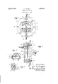
- Figure 1 is an elevation of a switch constructed in accordance with this invention having contacts normally. closed;
- Fi re 2 is a medial section of the same as on line 22 of Figure 1;
- Figure 3 is a view like a portion of Figure 2 but showing contacts normally open;
- Figure 4 is a side view of the switch.
- the switch has a base 1 adapted to be attached to a surface 4 by screws 2. Embedded in this base is a conductor 3, the inner end of which projects outward from the base to form a plain contact .point 3a as shown in Figure 2 or to form a hook-shaped point 3?) as in Figure 3. The outer end of this conductor constitutes a binding post 30.
- the base is also formed with a recess or socket 1a to receive the head of another binding post 4.
- the point 50 is hook-shaped so as to engage the similar shaped point 36 of the embedded conductor.
- the diaphragm disk is placed on the base as described, and a gasket 6 of non-conducting material is laid about its edge to fill the space between the base and top 7 not occupied by the diaphragm.
- the top 7 which comprises a ring 7a and a yoke 7 b upstanding therefrom is placed over the gasket, there being holes-to accommodate the binding posts, and clamped to the base by the bolts 8.
- a thermally responsive element 9 is a frangible bulb made of glass, quartz or the like and containing a charge which upon being heated to predetermined degree will completely destroy the bulb.
- the latter has the usual drawnout ends, the inner of which rests on a suitable seat 10 provided at the center of the diaphragm, and the outer of which rests in an adjusting screw 11 which screws through a sleeve 12 in the yoke 76. When assembled, the shank of this screw extends outside the sleeve and is slotted (as indicated in dotted outline in Figure 2) so that it may be turned w between the points 5?) and 3a.
- the screw 11 In setting the switch of Figure 2, the screw 11 is turned inward forcing the'bulb and diaphragm ahead of it, until contact is made This can be determined by temporarily connecting the binding posts 30 and 4 to the leads of a signal circuit. After contact is announced by the signal the screw 11 is given an extra half turn to insure good contact and then its shank is cut ofi flush with sleeve 12 to guard against unwarranted disturbance of the setting.
- the switch of Figure 3 is similarly set, the screw 11 being turned inward until the cessation of the signal indicates that the point y or makes the contact between the points de- 7 50 has separated from point 3?). An extra half turn is given the screw 11 and it is then out ofi as previously described.
- the switch can be attached to any surface desired and the leads 13, 14 of the circuit which it controls can be attached to the binding posts 30 and 6 respectively, the nuts 15 serving also to augment clamps 8 in holding the top securely to the base.
- the contact points are entirely housed within the chamber 16 formed by the base and diaphragm.
- This chamber is moisture proof and consequently the points are not at all liable to corrode or receive a deposit of any foreign material.
- the diaphragm is preferably made of bronze, and circularly corrugated for strength and resiliency. It may be plated with chromium as may also the bronze seat 10 and adjusting screw 11.
- the base and top as shown are molded insulating material such as bakelite, and the bulb is of quartz, glass or the like.
- the entire switch can most conveniently comprise materials not susceptible to corrosive action and therefore it can be placed in any atmosphere, such as that of a dip tank, smoke flue, and so forth without regard to the corrosive influence thereof. And since no fusible material is employed there is no cold flow to be watched and guarded against.
- Bulbs of the sort here shown are now available commercially and give way with substantial accuracy at a definite temperature.
- the diaphragm 5 springs outward toward the yoke and either breaks pending upon whether a normally closed or open switch is used. In either case the movement of the points is rapid with no arcing,
- Thischaracteristic of the switch is due to the use of the frangible bulb as the thermally responsive element. It remains substantially unchanged until shattered completely, thereby releasing'at once all restraint on the diaphragm.
- a thermostatic switch comprising a base; a yieldable plate supported on said base and forming therewith an enclosed chamber; a fixed contact point in said chamber; a contact point on the chamber side of said plate adapted to coact with the fixed contact point; a frangible vessel and a fixed support therefor arranged at such a distance from said plate that the vessel when interposed between said support and plate will cause said plate to yield and thereby position its contact point with respect to the fixed point ;'said frangible vessel containing a charge adapted upon being heatedto a predetermined degree to destroy said vessel and thereby permit said plate to return to its initial position and thus change the relative positions of the contact points.
- a thermostatic switch having a base and a fixed conductor associated therewith; a top mountedon said base having a yoke; a diaphragm interposed between said base and top, and adapted to coact with said fixed conductor to make or break an electric circuit; and a charged frangible container interposed between said yoke and said diaphragm normally holding said diaphragmin a selected position with respect to said conductor;the charge in said vessel being adapted upon rise of temperature to a predetermined degree to destroy said vessel and thereby permit said diaphragm to flex and thus alter its position with respect to said conductor.
- a thermostatic switch having a base and a fixed contact point associated therewith; a top mounted on said base having a yoke; a diaphragm supported between said base and top having a contact point arranged to coact with the fixed contact point; a frangible vessel interposed between said diaphragm and said yoke; and means for adjusting the position of said vessel so as to flex said diaphragm and hold its contact point in a selected position with respect to said fixed contact oint; the said vessel containing a charge a apted upon being heated to a predetermined degree to destroy said vessel and thereby permit the diaphragm to return to its initial position and. thus change the relation between the contact points. 4.
- a thermostatic I switch comprising a base having-a fixed contact point associated therewith; a yieldable element supported on said base and forming therewith a closed chamber; a contact point associated with said element and arranged to coact with the fixed contact point inside said chamber; a support attached to said base and overlying said element; and means interposed between said support and said element normally holding said yieldable element in position to maintain a predetermined relation between said contact points; the said means remaining undisturbed as respects the holding of said element until a predetermined temperature is reached and then giving way at said temperature to permit the element to yield and thereby alter the relation of said contact points with respect to one another.
Description
April 5, 1932. 1. w. KNIGHT THERMOSTATIC SWITCH Filed March 23, 1929 ,[77 0677 it: 7 19 Id 1? 7160 711 Patented Apr. 5, 1932 UNITED STATES PATENT OFFICE IRA. W. KNIGHT, OF PROVIDENCE, RHODE ISLANQD, ASSIGNOR TO GENERAL FIRE EXTINGUISHER COMPANY, OF PROVIDENCE RHODE ISLAND, A CORPORATION 01' DELAWARE THERMOSTA'IIG swIToH Application filed Mai-ch 23, 1929. Serial No. 349,359.
This invention relates to improvements in thermostatic switches.
It is an object of this invention to provide a switch which will change its normal position abruptly-upon the temperature in its vicinity reaching a predetermined degree.
Tothis end the contact elements, tending con- It is a feature of the switch illustrative of this invention, that its contact points are completely housed so as to be entirely free from thedanger of corrosion. Likewise the thermal element selected is not subject to corrosion. This insures a switch which can be exposed for an indefinite time to gases or liquids which tend to cause corrosion, and still be ready to function whenever the need arises.
It is intended that the patent shall cover by suitable expression in the appended claims whatever features of patentable novelty exist in the invention disclosed. v
In the accompanying drawings,
Figure 1 is an elevation of a switch constructed in accordance with this invention having contacts normally. closed;
Figure 3 is a view like a portion of Figure 2 but showing contacts normally open; and
Figure 4 is a side view of the switch.
Referring to the drawings, the switch has a base 1 adapted to be attached to a surface 4 by screws 2. Embedded in this base is a conductor 3, the inner end of which projects outward from the base to form a plain contact .point 3a as shown in Figure 2 or to form a hook-shaped point 3?) as in Figure 3. The outer end of this conductor constitutes a binding post 30. The base is also formed with a recess or socket 1a to receive the head of another binding post 4.
A diaphragm disk 5 made of a metal which is a good conductor, such for example as bronze, is placed on the base 1 with its eriphery spaced from the binding post 30, ut with a portion of the diaphragm extending around the post 4 and preferably soldered thereto. On the inside of this disk, at its center, is a contact point which as seen in Figure 2 is a true point 5?) arranged to overlie point 3a. In the switch'of Figure 3, the point 50 is hook-shaped so as to engage the similar shaped point 36 of the embedded conductor.
The diaphragm disk is placed on the base as described, and a gasket 6 of non-conducting material is laid about its edge to fill the space between the base and top 7 not occupied by the diaphragm. The top 7 which comprises a ring 7a and a yoke 7 b upstanding therefrom is placed over the gasket, there being holes-to accommodate the binding posts, and clamped to the base by the bolts 8.
Between the yoke 7 b and the diaphragm 5 is placed a thermally responsive element 9. Preferably this element is a frangible bulb made of glass, quartz or the like and containing a charge which upon being heated to predetermined degree will completely destroy the bulb. The latter has the usual drawnout ends, the inner of which rests on a suitable seat 10 provided at the center of the diaphragm, and the outer of which rests in an adjusting screw 11 which screws through a sleeve 12 in the yoke 76. When assembled, the shank of this screw extends outside the sleeve and is slotted (as indicated in dotted outline in Figure 2) so that it may be turned w between the points 5?) and 3a.
to force the bulb and center of the diaphragm toward the base.
In setting the switch of Figure 2, the screw 11 is turned inward forcing the'bulb and diaphragm ahead of it, until contact is made This can be determined by temporarily connecting the binding posts 30 and 4 to the leads of a signal circuit. After contact is announced by the signal the screw 11 is given an extra half turn to insure good contact and then its shank is cut ofi flush with sleeve 12 to guard against unwarranted disturbance of the setting.
The switch of Figure 3 is similarly set, the screw 11 being turned inward until the cessation of the signal indicates that the point y or makes the contact between the points de- 7 50 has separated from point 3?). An extra half turn is given the screw 11 and it is then out ofi as previously described. The switch can be attached to any surface desired and the leads 13, 14 of the circuit which it controls can be attached to the binding posts 30 and 6 respectively, the nuts 15 serving also to augment clamps 8 in holding the top securely to the base. i
It is to be noted that the contact points are entirely housed within the chamber 16 formed by the base and diaphragm. This chamber is moisture proof and consequently the points are not at all liable to corrode or receive a deposit of any foreign material. The diaphragm is preferably made of bronze, and circularly corrugated for strength and resiliency. It may be plated with chromium as may also the bronze seat 10 and adjusting screw 11. The base and top as shown are molded insulating material such as bakelite, and the bulb is of quartz, glass or the like. In short, the entire switch can most conveniently comprise materials not susceptible to corrosive action and therefore it can be placed in any atmosphere, such as that of a dip tank, smoke flue, and so forth without regard to the corrosive influence thereof. And since no fusible material is employed there is no cold flow to be watched and guarded against.
Bulbs of the sort here shown are now available commercially and give way with substantial accuracy at a definite temperature. When this occurs the diaphragm 5 springs outward toward the yoke and either breaks pending upon whether a normally closed or open switch is used. In either case the movement of the points is rapid with no arcing,
and the circuit is instantly broken or made: Thischaracteristic of the switch is due to the use of the frangible bulb as the thermally responsive element. It remains substantially unchanged until shattered completely, thereby releasing'at once all restraint on the diaphragm.
After a switch has operated, it can easily be reset by putting in a new bulb and adjusting screw, the latter of course replacing the old one and being itself cut off when the adjustment is complete.
I claim:
1. A thermostatic switch comprising a base; a yieldable plate supported on said base and forming therewith an enclosed chamber; a fixed contact point in said chamber; a contact point on the chamber side of said plate adapted to coact with the fixed contact point; a frangible vessel and a fixed support therefor arranged at such a distance from said plate that the vessel when interposed between said support and plate will cause said plate to yield and thereby position its contact point with respect to the fixed point ;'said frangible vessel containing a charge adapted upon being heatedto a predetermined degree to destroy said vessel and thereby permit said plate to return to its initial position and thus change the relative positions of the contact points.
2. A thermostatic switch having a base and a fixed conductor associated therewith; a top mountedon said base having a yoke; a diaphragm interposed between said base and top, and adapted to coact with said fixed conductor to make or break an electric circuit; and a charged frangible container interposed between said yoke and said diaphragm normally holding said diaphragmin a selected position with respect to said conductor;the charge in said vessel being adapted upon rise of temperature to a predetermined degree to destroy said vessel and thereby permit said diaphragm to flex and thus alter its position with respect to said conductor.
3. A thermostatic switch having a base and a fixed contact point associated therewith; a top mounted on said base having a yoke; a diaphragm supported between said base and top having a contact point arranged to coact with the fixed contact point; a frangible vessel interposed between said diaphragm and said yoke; and means for adjusting the position of said vessel so as to flex said diaphragm and hold its contact point in a selected position with respect to said fixed contact oint; the said vessel containing a charge a apted upon being heated to a predetermined degree to destroy said vessel and thereby permit the diaphragm to return to its initial position and. thus change the relation between the contact points. 4. A thermostatic I switch comprising a base having-a fixed contact point associated therewith; a yieldable element supported on said base and forming therewith a closed chamber; a contact point associated with said element and arranged to coact with the fixed contact point inside said chamber; a support attached to said base and overlying said element; and means interposed between said support and said element normally holding said yieldable element in position to maintain a predetermined relation between said contact points; the said means remaining undisturbed as respects the holding of said element until a predetermined temperature is reached and then giving way at said temperature to permit the element to yield and thereby alter the relation of said contact points with respect to one another.
Signed at Providence, Rhode Island, this 22nd day of March, 1929.
IRA W. KNIGHT.
Priority Applications (1)
| Application Number | Priority Date | Filing Date | Title |
|---|---|---|---|
| US349359A US1852312A (en) | 1929-03-23 | 1929-03-23 | Thermostatic switch |
Applications Claiming Priority (1)
| Application Number | Priority Date | Filing Date | Title |
|---|---|---|---|
| US349359A US1852312A (en) | 1929-03-23 | 1929-03-23 | Thermostatic switch |
Publications (1)
| Publication Number | Publication Date |
|---|---|
| US1852312A true US1852312A (en) | 1932-04-05 |
Family
ID=23372059
Family Applications (1)
| Application Number | Title | Priority Date | Filing Date |
|---|---|---|---|
| US349359A Expired - Lifetime US1852312A (en) | 1929-03-23 | 1929-03-23 | Thermostatic switch |
Country Status (1)
| Country | Link |
|---|---|
| US (1) | US1852312A (en) |
Cited By (2)
| Publication number | Priority date | Publication date | Assignee | Title |
|---|---|---|---|---|
| DE915360C (en) * | 1941-09-04 | 1954-07-19 | Eberle & Co Appbau Ges | Device for breaking a circuit if a certain outside temperature is exceeded |
| US3043937A (en) * | 1959-07-28 | 1962-07-10 | Filtron Company Inc | Electrical control means |
-
1929
- 1929-03-23 US US349359A patent/US1852312A/en not_active Expired - Lifetime
Cited By (2)
| Publication number | Priority date | Publication date | Assignee | Title |
|---|---|---|---|---|
| DE915360C (en) * | 1941-09-04 | 1954-07-19 | Eberle & Co Appbau Ges | Device for breaking a circuit if a certain outside temperature is exceeded |
| US3043937A (en) * | 1959-07-28 | 1962-07-10 | Filtron Company Inc | Electrical control means |
Similar Documents
| Publication | Publication Date | Title |
|---|---|---|
| JPH0561756B2 (en) | ||
| GB2111750A (en) | Thermosensitive cut out | |
| US1852312A (en) | Thermostatic switch | |
| US2029097A (en) | Electric fire alarm | |
| US3602863A (en) | Adjustable thermostat | |
| US360823A (en) | Electric thermostat or fire-alarm | |
| US243345A (en) | Adam lttngen | |
| US3223806A (en) | Thermally controlled electrical switch having motion-amplifying lever means | |
| US2211520A (en) | Electrical heating unit | |
| US3581263A (en) | Thermally responsive switch | |
| US3255331A (en) | Immersion thermostatic switch | |
| US1986507A (en) | Thermostatic switch | |
| US643179A (en) | Thermostatic apparatus. | |
| US1181630A (en) | Circuit-closer for fire-alarm systems. | |
| US560023A (en) | Thermostat | |
| US1484816A (en) | Thermostatic circuit-controlling device | |
| US3271547A (en) | Fire detector device | |
| US1398153A (en) | Thermal circuit-closer | |
| US2038970A (en) | Circuit breaker plug | |
| US721451A (en) | Thermostat. | |
| US727315A (en) | Thermal electric fire-alarm. | |
| US627322A (en) | Thermostatic instrument | |
| US740254A (en) | Thermostat. | |
| US912433A (en) | Alarm for signal-lamps. | |
| US748323A (en) | Thermostat. |