US1852234A - Traverse cord separator - Google Patents
Traverse cord separator Download PDFInfo
- Publication number
- US1852234A US1852234A US509710A US50971031A US1852234A US 1852234 A US1852234 A US 1852234A US 509710 A US509710 A US 509710A US 50971031 A US50971031 A US 50971031A US 1852234 A US1852234 A US 1852234A
- Authority
- US
- United States
- Prior art keywords
- cord
- traverse
- sheaves
- separator
- traverse cord
- Prior art date
- Legal status (The legal status is an assumption and is not a legal conclusion. Google has not performed a legal analysis and makes no representation as to the accuracy of the status listed.)
- Expired - Lifetime
Links
- 230000015572 biosynthetic process Effects 0.000 description 10
- 238000005755 formation reaction Methods 0.000 description 10
- 239000000725 suspension Substances 0.000 description 2
- 241000507564 Aplanes Species 0.000 description 1
Images
Classifications
-
- A—HUMAN NECESSITIES
- A47—FURNITURE; DOMESTIC ARTICLES OR APPLIANCES; COFFEE MILLS; SPICE MILLS; SUCTION CLEANERS IN GENERAL
- A47H—FURNISHINGS FOR WINDOWS OR DOORS
- A47H3/00—Fastening, clamping, or guiding devices for the bands or cords of curtains or the like
- A47H3/02—Fastening, clamping, or guiding devices for bands or cords
- A47H3/10—Cord guides
Definitions
- This invention relates to improvementsin drapery suspension means and more particularly to means for preventing the twisting about each other of the draw or traverse cords connected with the slides mounted upon or within curtain rods and curtain poles for spacing curtains or draperies from each other and bringing them together, respectively.
- a traverse cord is trained over a pair of sheaves or pulleys mountedin or uponone end of a curtain rod or pole and usually disposed side by side or in other very close proximity to each other, said sheave or pulley at the other end of the curtain rod or pole and is connected at one end with the master carrier of the set carrying one drape or curtain of a pair, and being connected at a point between its ends with the master carrier of the set carrying the other drape or curtaino-f the pair.
- the main object of the present invention is to provide a very simple, cheap and efiicient device with which the depending end portions of a drawor traverse cord are engaged and maintained in spacedrelation to each other and which automatically responds to tension on one of either ends of the cord, as the latter is operated to eflect relative movement of a pair of draperies, to cause said operated cord end to align itself throughout'its length withthe sheave or pulley of the curtain. rod or pole over which said cord end is trained, thereby reducing frictional resistance to operation of said cord and, more especially, to prevent said cord end from becoming so angularly disposed. with respect to 7 fecting its efficiency;
- Another object of the invention is to provide cord guide formations in the device of thisinvention which will permit the depending cord ends to be threaded into the same without necessitating removal" of the weights at the extremities of said draw or traverse cord.
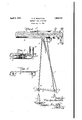
- FIG. 1 has illustrated a suitable embodiment of the in-' Fig. '1 is a fragmentary perspective viewof one end portion of a conventional type'of fiat hollow curtain rod equipped with a traverse cord and a traverse cord separator constructed in accordance with the invention, the said separator also being shown in perspective.
- Fig. 2 is aplan section on the line 22 of Fig. 1;
- Fig. 3 is a plan section on the line 3-3 of Fig. 1.
- the present invention comprises what may -be termed a pendulum device which, in the embodiment illustrated, comprises a stem or shank 1 terminating at its upper end in a hook 2 by means of which the device is suitably pivotally suspended from a convenient supporting element, and equipped at its lower end with a lateral arm 3 provided atitsouter and inner ends with suitable loop or eye formations 4 'an'd 5,;respectively, said eye formations being helical in the instance illustrated to permit the end portionsfi and 7 respectively, of the draw or traverse cord of the curtain rod 8 to be threaded into said:
- the hook 2 engages in a perforation of the plate 10 constituting the carrier for the sheaves over which the draw cord is trained, the position of the hook 2 with respect to the arm 3 being such as will normally cause said arm 3' to be positioned substantially parallel with the "face of the window casing to which thewall "pendulum,i'thus causing the eye formatio n thereof through which the cord end subjected to manual tension is trained to become substantially vertically aligned with the sheave over which the said cord end is trained and with the weight at the extremity of said end portion of the cord, 7
- the'main' functions of the device are, first, to maintain the depending end portions of the cord spaced sufli'ciently far apart to prevent them from twisting about each other or, in the event that they should become twisted about each other during manual manipulation thereof, to cause them to become disengaged automatically from each other, and, second, to maintain said depending end portions of the cord substantially in the respective vertical planes of the sheaves over which they are trained, the swinging of the device as above described being of more or less secondary importance.
- the point of suspension of the device may be offset laterally from the verticalplanes of the grooves of the sheaves from which said end portions of the cords are suspended as the weights of saidcords are such as to maintain the latter sufiiciently taut to swing and maintain the lower end portion of the device into position to bring the eye formations thereof into the Vertical planes of the grooves of the said sheaves.
- 'A traverse cord separator for a drapery fixture equipped with a traverse cord and sheavesover which said cord is trained, said separator comprising a member suspended from said fixture and equipped at points below said fixture and spaced from each other with guide formations in which the depending end portions of said cord are adapted to engage, said guide formations being disposed substantially in alignment with the grooves of the sheaves from which the said iend'portions of thecord are suspended, said separater being capable of limited pivotal movement relatively to said fixture.
- VA traverse cord separator for a drapery supporting element disposed parallel with and spaced from a window casing and equipped adjacent one of its ends with a pair of sheaves over which a traverse cord is adapted to be trained and from which the end portions of said cord depend, said isep-arator comprisinga pivotally suspended member equipped in its lower endv portion with guide formations spaced from each other and each operatively engaged with anendportion of said cord I 7 3.
- a traversecord separator for a drapery supporting element disposed parallel with and" spaced from a window casing and equipped adjacent one of its ends with apair of sheaves over -which a traverse cord is);
- VA traverse cord separator for a drapery supporting element disposed parallel with and spaced from a window casing and of sheaves over which a traverse cord is adapted to be trained and from which the end portions of said cord depend, saidseparator comprisinga pendulum member-pivotof rotation of said sheaves and equipped in its lower end with a pair of spaced apart eye formations through which said respective of rotation of;
Description
April '5, 1932- E. R. DOOLITTLE 1,852,234
TRAVERSE CORD SEPARATOR' Filed Jan. 19. 1931 T M T3 Patented Apr. 5, 1932 UNITED STATES PATENT OFFICE;
EVA RAE DOOLITTLE', or STURGIS, MICHIGAN, Assrenon To KIRSCHCQMPANY, or
STURGIS, MICHIGAN, a CORPORATION or MICHIGAN 1 TRAVERSE com) SEPARATOR Application filed January 19, 1931. Serial No. 509,710.
This invention relates to improvementsin drapery suspension means and more particularly to means for preventing the twisting about each other of the draw or traverse cords connected with the slides mounted upon or within curtain rods and curtain poles for spacing curtains or draperies from each other and bringing them together, respectively.
In the art to which the invention relates,
o a traverse cord is trained over a pair of sheaves or pulleys mountedin or uponone end of a curtain rod or pole and usually disposed side by side or in other very close proximity to each other, said sheave or pulley at the other end of the curtain rod or pole and is connected at one end with the master carrier of the set carrying one drape or curtain of a pair, and being connected at a point between its ends with the master carrier of the set carrying the other drape or curtaino-f the pair. I
Owing to the close proximity of the depending end portions of the traverse cords to each other, they invariably twist themselves about eachother so that, in attempting to manipulate said cords, the operator must first see the relative positions of the customary weights disposed upon the extremities of the cords to ascertain which of the cords must be drawn down to adjust the curtains .or draperies to a different relative position and, because of the resistance to operation resulting from the intertwining of said ends of the hand and because the screw eyes are disposed out of vertical alignment with the sheaves or pulleys and tends to cause or does cause the cord to leave the grooves of said sheaves, and
also increases the resistance tooperation of the cord ends.
The main object of the present invention is to provide a very simple, cheap and efiicient device with which the depending end portions of a drawor traverse cord are engaged and maintained in spacedrelation to each other and which automatically responds to tension on one of either ends of the cord, as the latter is operated to eflect relative movement of a pair of draperies, to cause said operated cord end to align itself throughout'its length withthe sheave or pulley of the curtain. rod or pole over which said cord end is trained, thereby reducing frictional resistance to operation of said cord and, more especially, to prevent said cord end from becoming so angularly disposed. with respect to 7 fecting its efficiency;
Another object of the invention is to provide cord guide formations in the device of thisinvention which will permit the depending cord ends to be threaded into the same without necessitating removal" of the weights at the extremities of said draw or traverse cord.
In the accompanying drawings,
1 have illustrated a suitable embodiment of the in-' Fig. '1 is a fragmentary perspective viewof one end portion of a conventional type'of fiat hollow curtain rod equipped with a traverse cord and a traverse cord separator constructed in accordance with the invention, the said separator also being shown in perspective. i
Fig. 2 is aplan section on the line 22 of Fig. 1;
Fig. 3 is a plan section on the line 3-3 of Fig. 1.
The present invention comprises what may -be termed a pendulum device which, in the embodiment illustrated, comprises a stem or shank 1 terminating at its upper end in a hook 2 by means of which the device is suitably pivotally suspended from a convenient supporting element, and equipped at its lower end with a lateral arm 3 provided atitsouter and inner ends with suitable loop or eye formations 4 'an'd 5,;respectively, said eye formations being helical in the instance illustrated to permit the end portionsfi and 7 respectively, of the draw or traverse cord of the curtain rod 8 to be threaded into said:
loop or eye formations 4iand 5, respectively, without first detaching the weights 9 from said cord. i V In the instance illustrated, the hook 2 engages in a perforation of the plate 10 constituting the carrier for the sheaves over which the draw cord is trained, the position of the hook 2 with respect to the arm 3 being such as will normally cause said arm 3' to be positioned substantially parallel with the "face of the window casing to which thewall "pendulum,i'thus causing the eye formatio n thereof through which the cord end subjected to manual tension is trained to become substantially vertically aligned with the sheave over which the said cord end is trained and with the weight at the extremity of said end portion of the cord, 7
However, the'main' functions of the device are, first, to maintain the depending end portions of the cord spaced sufli'ciently far apart to prevent them from twisting about each other or, in the event that they should become twisted about each other during manual manipulation thereof, to cause them to become disengaged automatically from each other, and, second, to maintain said depending end portions of the cord substantially in the respective vertical planes of the sheaves over which they are trained, the swinging of the device as above described being of more or less secondary importance.
- Obviously, the point of suspension of the device may be offset laterally from the verticalplanes of the grooves of the sheaves from which said end portions of the cords are suspended as the weights of saidcords are such as to maintain the latter sufiiciently taut to swing and maintain the lower end portion of the device into position to bring the eye formations thereof into the Vertical planes of the grooves of the said sheaves.
Obviously, any guide means equivalent to the eye formations of the device shown and described may be used and the structural features of said device changed and varied as desired, without departing from the invention. ashdefined in the appended claims.
vI claim as my invention: v
' 1. 'A traverse cord separator for a drapery fixture equipped with a traverse cord and sheavesover which said cord is trained, said separator comprising a member suspended from said fixture and equipped at points below said fixture and spaced from each other with guide formations in which the depending end portions of said cord are adapted to engage, said guide formations being disposed substantially in alignment with the grooves of the sheaves from which the said iend'portions of thecord are suspended, said separater being capable of limited pivotal movement relatively to said fixture.
2. VA traverse cord separator for a drapery supporting element disposed parallel with and spaced from a window casing and equipped adjacent one of its ends with a pair of sheaves over which a traverse cord is adapted to be trained and from which the end portions of said cord depend, said isep-arator comprisinga pivotally suspended member equipped in its lower endv portion with guide formations spaced from each other and each operatively engaged with anendportion of said cord I 7 3. A traversecord separator for a drapery supporting element disposed parallel with and" spaced from a window casing and equipped adjacent one of its ends with apair of sheaves over -which a traverse cord is);
grooves of said sheaves and below the latter.
4:. VA traverse cord separator for a drapery supporting element disposed parallel with and spaced from a window casing and of sheaves over which a traverse cord is adapted to be trained and from which the end portions of said cord depend, saidseparator comprisinga pendulum member-pivotof rotation of said sheaves and equipped in its lower end with a pair of spaced apart eye formations through which said respective of rotation of;
a vertical plane substantially common tothe fr i .v equipped ad acent one of its ends with a pair x1 ally engaged with said element at its upper end to swing on an axis parallel with the axis EVA QRAE DOOLITTLE.
Priority Applications (1)
| Application Number | Priority Date | Filing Date | Title |
|---|---|---|---|
| US509710A US1852234A (en) | 1931-01-19 | 1931-01-19 | Traverse cord separator |
Applications Claiming Priority (1)
| Application Number | Priority Date | Filing Date | Title |
|---|---|---|---|
| US509710A US1852234A (en) | 1931-01-19 | 1931-01-19 | Traverse cord separator |
Publications (1)
| Publication Number | Publication Date |
|---|---|
| US1852234A true US1852234A (en) | 1932-04-05 |
Family
ID=24027794
Family Applications (1)
| Application Number | Title | Priority Date | Filing Date |
|---|---|---|---|
| US509710A Expired - Lifetime US1852234A (en) | 1931-01-19 | 1931-01-19 | Traverse cord separator |
Country Status (1)
| Country | Link |
|---|---|
| US (1) | US1852234A (en) |
-
1931
- 1931-01-19 US US509710A patent/US1852234A/en not_active Expired - Lifetime
Similar Documents
| Publication | Publication Date | Title |
|---|---|---|
| US2493108A (en) | Akticle handler | |
| US2276716A (en) | Venetian blind | |
| US1852234A (en) | Traverse cord separator | |
| US4244549A (en) | Self straightening picture hanger | |
| US1876061A (en) | Drapery suspension device | |
| US2091033A (en) | Venetian blind fixture | |
| CN108487849A (en) | Weight adjusting device, built-in manipulation handle and hollow shutter | |
| US3360292A (en) | Grapple | |
| US1498594A (en) | Window-curtain support | |
| CN207658834U (en) | A kind of anti-drop device of harness cord thread spool | |
| US2091032A (en) | Venetian blind operating fixture | |
| US2875971A (en) | Venetian blind rack | |
| US2314354A (en) | Awning hanger | |
| US2493186A (en) | Venetian blind | |
| CN208087966U (en) | A kind of hand pulling type clothes hanger | |
| US1876060A (en) | Draw cord equipment for telescopically extensible curtain rods | |
| US2587114A (en) | Control device | |
| US2055826A (en) | Venetian blind lifting device | |
| US2064094A (en) | Venetian blind | |
| US2398524A (en) | Venetian blind holder | |
| US2939528A (en) | Venetian blind | |
| US2528297A (en) | Means for preventing singling in spinning operations | |
| US1954720A (en) | Hanger | |
| US1856140A (en) | Spooling device | |
| US1907648A (en) | Drapery fixture |