US1852048A - Trenching machine - Google Patents
Trenching machine Download PDFInfo
- Publication number
- US1852048A US1852048A US240402A US24040227A US1852048A US 1852048 A US1852048 A US 1852048A US 240402 A US240402 A US 240402A US 24040227 A US24040227 A US 24040227A US 1852048 A US1852048 A US 1852048A
- Authority
- US
- United States
- Prior art keywords
- frame
- wheel
- digging
- guide
- supporting
- Prior art date
- Legal status (The legal status is an assumption and is not a legal conclusion. Google has not performed a legal analysis and makes no representation as to the accuracy of the status listed.)
- Expired - Lifetime
Links
Images

Classifications
-
- E—FIXED CONSTRUCTIONS
- E02—HYDRAULIC ENGINEERING; FOUNDATIONS; SOIL SHIFTING
- E02F—DREDGING; SOIL-SHIFTING
- E02F3/00—Dredgers; Soil-shifting machines
- E02F3/04—Dredgers; Soil-shifting machines mechanically-driven
- E02F3/18—Dredgers; Soil-shifting machines mechanically-driven with digging wheels turning round an axis, e.g. bucket-type wheels
Definitions
- This invention relates to machines for digging ditches or trenches, but more particularly to a machine of this character which is mobile, and is adapted to excavate as it moves over the ground.
- An important object of this invention is to provide a simple and efiicient machine of the traction type for digging ditches and trenches having adjustable features to enable the width of the ditch or trench to be varied, as desired.
- Another object is to provide a reliable trenching machine of the above type having the new and improved features of construction and arrangement hereinafter described.
- Fig. 1 is atop plan view of a trenching ma- 2@ chine.
- Fig. 2 is a side elevation of the machine.
- Fig. 3 is a rear end elevation partly in section and with some parts removed.”
- Fig. 4 is a fragmentary top plan view of the guide and frame and a portion of the digging wheel frame.
- Fig. 5 is a rear elevation of the guide frame.
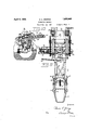
- FIG. 6 is a fragmentary elevation through the central portion of the machine showing the driving mechanism for the digging wheel.
- Fig. 7 is a top plan view of the digging wheel frame.
- Fig. 8 is a side elevation of the digging wheel and digging wheel frame.
- Fig. 9 is a front end view of the digging wheel frame showing a fragmentary section of the digging wheel and a portion of'the conswinging to one side or the other of the main p i frame so that the width of the trenchmay be varied. It will be apparent. that a wide trench may be dug by positioning the digging wh'eelat an'acute angle with respect to the main frame A, or a relatively narrow ditch may be made by arranging the wheel in line with the main frame.
- a sup porting frame D Spaced above the guide frame is a sup porting frame D, which also has horizontal swinging movements.
- the supporting frame cooperates with the guide frame for supporting the digging wheel B, and is flexibly connected thereto by a cable arrangement which is operated by a winch to raise or lower the digging wheel.
- Power driven mechanism is provided for conjointly swinging the guide frame C in one direction and the supporting frame D in the opposite direction.
- the result of this movement is that the outer part of the diggingwheel B .may be swungto one side or the other of the main frame, and the inner part nearestthe main frame is moved to the opposite side. This enables the angular position of the digging wheel to be readily varied by power means.
- a conveyor F For delivering theearth dug by the digging wheel B to one side, a conveyor F is positioned adjacent the wheel.
- the con veyor is supported at the outer end by a cable suspended from a boom, the inner end being attached to the digging wheel frame.
- the machine is propelled over the ground by traction units G of the caterpillar type, and one of the units is horizontally extensible so that a relatively wide or narrow area may be spanned by the machine.
- Power means in the form of rack and pinion is employed to move one traction unit toward or away from the main frame. This enables the machine to operate even thoughfit has to move over a ditch of considerable width,
- the main frame A of the machine comprises a pair of side beams 1 which are connected by cross beams 2 and suitable auxiliary braces.
- a digging wheel B In rear of the main frame is a digging wheel B, which consists of a rim 4 to the outer sides of'which a series of buckets 5 are secured. On opposite sides of the ring or rim 4; are series of gear teeth 6 which are engaged by driving gears 7 carried by opposite sides of the digging wheel frame.
- the digging wheel frame is made up of longitudinal beams 8 positioned on opposite sides of the digging wheel B and cross bars connecting the beams 8. Secured to bars 9 on the underside of the beams 8 is a rectangular frame 10, to the lower cornersof which are securedpairs of gears 11 and 12, respectively. A shield 4 secured to the front portion of the frame 10 prevents thedischarge of-earth from the buckets until they reach the conveyor F.
- the gears 11 and 12 mesh with the teeth 6 on the rim 4 and have in wardly spaced rollers which assist in holeingthe rim 4 in the proper position.
- a pair of rollers 13 above the gears 11 assist in holdingthe digging wheel, and. it
- pairs of cuttersti and 6 are connected to opposite sides of the lower end of-therectangular frame 10.
- the cutter 5 is composed of a pair of blades and is directly geared to the teeth 6 of the rim 4 while the cutter 6 in advance of-the cutter has four blades and is operatively geared to the rim teeth 6 through a sprocket'and chain connection 7
- the blades of the cutters are outwardly bowed at the outer ends, and these cutters loosen the earth asthe digging wheel B moves forwardly.
- each bracket 16 is a large central roller 17, and in front of the roller 17 is a pair of smaller transversely spaced rollers 18.
- the rollers 17 and 18 are'arranged to fit over an 2 I-beam for a purpose hereinafter described.
- the guide frame O is mounted on the main frame A and is composed of a cross bar 19 at the rear end, and extendingfrom the bar 19 are parallel side bars 20. .A'bracket 21'is connectedlto the front ends of the side bars with an upright stub shaft 22 mounted on the main frame. Rising from opposite ends of the cross bar19 are inclined uprights 22 to the upper ends of which bars 23 are secured. The bars 23 extend downwardly and forwardly, and are secured at their front ends to the bracket 21. Braces 24 connect the intermediate portions of the uprights 22 and bars 20.
- a curved track 26 on the main frame extends from one side to the other and rollers 25 secured to the underside of the end portions of .the cross beam 19 are movable over the track 26. It is apparent from the above description that the carriage frame C may swing horizontally or transversely across the main frame A over the track 26 and about the stud shaft 22 as a pivot.
- braces 23 of the carriage frame extend beyond the inplate 27 is pivoted to a transverse beam-28 fixed to a pair of spaced upright guides 29, in the form of I-beams, the upper ends of which extend considerably above the guide frame C.
- a gear housing 30 which provides a support for the lower end of a vertical shaft 31 Extending across the lower portion of the uprights 29 is a plate 31 to t e rear side of which is fixed a bearing 32 for the shaft 31, and the bearing 82 rests upon and is supported by the gear housing 30. It is apparent that the upright guide beams 29 are pivotally connected to the guide frame C and are adapted to swing as a unit horizontally relatively thereto.
- the digging wheel frame is vertically slidable on the upright guides 29, the rollers 17 and 18 of the brackets 16 on the digging wheel frame fitting over the beams 29.
- V t V t
- the power unit 32 is connected through a sprocket and chain 33 with a set of beveled gears 34 for operatively driving a shaft 35 I end of the vertical shaft 31 meshes with a differential 40 which has a transverse shaft 41 mounted on the vertical guide beams 29.
- the ends of the shaft 41 have gear and sprocket connections 42 with opposite ends of a shaft 43 on the digging wheel frame.
- the driving gears 7 heretofore described for the digging wheel are fast to the shaft 43.
- an inverted U-frame 44 which extends across the main frame from one side to the other and inclined braces 45 connect the intermediate portion of the frame 44 with the main frame.
- a supporting carriage D which is composed of a pair of side beams 46 suitably braced and connected at its rear end i by a cross bar 47 and at the front end by a cross bar 48.
- the beveled gear arrangement 55 includes a clutch to enable the shaft to be driven in one direction or the other in orderthat the winch 51 may be rotated one direction or the other.
- the supporting carriage D is connected to support the rear end portion of the digging wheel B through a cable 56 which also connects with the guide frame 0, so that the guide frame C serves to support the front end portion of the digging wheel B.
- One end of the cable 56 is wound around the spool 52 of the winch 51, extends rearwardly to a sheave 57 on the outer end of the carriage D and extends downwardly to a sheave 58 on the rear end portion of the digging wheel frame. From the sheave 58 the cable 56 extends forwardly to a sheave 59 secured to the forward end portion of the digging wheel frame and then upwardly over a sheave 60 secured to the upperend of the adjacent vertical guide beam 29.
- the cable 56 From the sheave 60 the cable 56 extends downwardly to a sheave 61 adjacent the sheave 59, and then extends rearwardly to a sheave 62 adjacent the sheave 58. The cable then extends upwardly to a sheave 63 on the outer end of the supporting carriage D and from the sheave 63 the cable extends around a sheave 64 also on the end portion of the supporting carriage D. The cable 56 then passes,
- thedigging wheel is supported through the digging wheelframe and flexible cable 56, the rear end portion by may be moved toward one side of the main frame, and the inner portion may be moved toward the opposite side.
- the width of the trench may be regulated.
- the outer end portion of the diggingwheel' is moved away over to one side, arelativelywide trench can be dug, but when the digging wheel is disposed directly in line so that the axis of the wheel is substantially parallel to the main frame, a relatively narrow ditch may be dug of a size dependent uponv the width of the digging wheel buckets 5. It is apparent that by this construction and arrangemen't'a relatively small digging wheel may beutili'zed to excavate or dig a trench, the width of which may be greatly in excess of the width of the. digging wheel.
- a pair of cables are employed, each cable being connected respectively to the supporting carriage D and guide frame C and to a winch 58.
- a cable is secured at one end to an intermediate portion of the supporting carriage D, and extends about sheaves 66 arranged on one side of the machine to a winch 67 about which it is coiled several times.
- the cable 65 passes about a sheave 68 on the opposite side of the machine to the guide frame C.
- Adjacent the winch 67 is a winch 69, about which is wound a cable 70, one end of which is secured to the opposite side of the guide frame C.
- the cable extendsabout a sheave 71 on the adjacent side of the main frame and then across the main frame 11 to a sheave 7 2 on the opposite side.
- the cable 7 0 extends to the opposite side of the supporting carriage D where it is secured.
- a clutch 78 Between the winchs 67 and 69 is a clutch 78, a driving shaft 74 for the winches being suitably connected to the main power unit 82.
- a conveyor F extends through the diggingwheel B, and one end thereof is supported by the digging wheel frame.
- the conveyor consists of a frame 75 carrying a series of rollers 76, about which is trained an endless belt 77.
- the inner end of theframe is connected by U-bolts .78 to a tube 79 supported at its opposite ends by bearings 80 and 81 connected by bolts to elongated arcuate slots 82 and 88 respectively, formed in cross bars of the digging wheel frame. It is apparent "that the connection between the conveyor ing shaft 8% is arranged within the tube 79,
- drive shaft 81 is connected by set of bevelled in the housing 86 to the shaft as, which is driven by the main sprocket and chain connection 12'. The connection between the drive 8% and shaft position without disturbing the driving connection.
- the outer end portion of the conveyor F is supported by a boom 87 flexibly connected to the conveyor by a cable 88.
- One end'of the cable is wound about the outer spool 53 of the digging wheel winch 51 and from the spool the cable 88 passes over a sheave 89 on the upper portion of the frame 44, and then downwardly to a sheave 90' on the inner.
- end of the boom 87 From the sheave 90 the cable 88 extends over a sheave 91 on the outer end of the boom, and then downwardly around a sheave 92 connected to a bail 93 which is attached to the outer end of the conveyor frame. From the sheave 92 the cable 88 extends upwardly over a sheave 94 adjacent the sheave 91, and then around a sheave 95 to a hand wheel 96.
- the conveyor may be manually raised or lowered, but in the operation of the winch 51, it is to be understood that the conveyor F is simultaneously raised or lowered with the digging wheel B.
- a cable 97 is secured at one end to the inverted U-frame 14, and extends about a sheave 98 on the outer'end portion of the boom, and then forwardly to a sheave 99 on the frame tt. From the sheave 99 the cable 97 extends downwardly to handwheel 100.
- the hand wheel 100 By operating the hand wheel 100 the outer end of the boom is moved toward or away from the main frame, so that the conveyor may be moved forwardly or rearwardly, as desired.
- the inner end of the boom 87 has a universal connection 101 with the frame i l.
- the machine frame is propelled over the ground by caterpillar mechanism G, which consists of a relatively long traction unit 102 on one side, and a relatively short traction unit 103 on the opposite side.
- the detail construction of the traction units forms no part of the present invention, and it is deemed sufficient to say that the traction unit 102 has a sprocket and chain connection 108 with a shaft 104, which is suitably connected to be driven from the power'unit 82 j
- the mounting of the traction unit 103 is an important feature of the invention, and this traction unit is so supported and connected to the mainframe A that it may be moved away from or closer to the main frame. This enables the machine to be adapted to secure traction regardless of the width of the trench or the nature of the terrain.
- the traction unit 103' has a sprocket and chain connection 105 witha driving shaft 106 having a squared portion slidable through a drivlng gear 107.
- the gear 107 is suitably connected to be driven from the power unit 32 and detail descr1pt1on of the connections between the gear 107 and the power unit are not considered necessary.
- Bymeans of the squared portion of the driving shaft 106 the shaft may slide through the driving gear 107, but continue to transmit power to the operating parts of the traction unit 103.
- the main frame A is supported by a rectangular hollow beam 108, which is securely fixed to the main frame and the traction unit 102.
- Telescoping inside of the supporting beam 108 is abeam 109, which is securely fastened at its outer end to the traction unit 103, and secured to the upper side of the beam 109 is a rack 110, which is disposed in an elongated opening 111 in the main supporting beam 108. Meshing with the rack is a pinion 112 fixed to a shaft 113, and operative- 1y connected to be driven from the power unit 32.
- the traction unit 103 By driving the pinion 112 the traction unit 103 may be moved away from or towards the main frame A without disturbing the driving connection between the power unit 32 and the traction unit 108, as above described.
- the driving connection between the traction units 102 and 103, and the power unit 32 is such that the machine may be slowly propelled over the ground as the digging wheel operates to excavate a ditch or trench.
- a clutch is provided to enable the traction units to move at a faster rate of speed. Clutches are also provided for driving one traction unit or the other alone to enable the machine to turn in one direction or the other, as will be understood.
- the gear arrangement and connections for effecting these results form no part of the present invention, and detail description thereof is not considered necessary.
- a main frame a digging wheel, a frame for said wheel, a guide frame having a vertically disposed horizontally swingable guide, a orive shaft on said guide frame, means connecting said digging wheel and said guide for vertical movements thereon, a flexible drive between said drive shaft and said diggin wheel, a supporting carriage above said guide frame, a cable supporting connection between said supporting carriage and said digging wheel frame, and means for winding and unwinding said cable for raising or lowering said digging wheel.
- a main frame a digging wheel, a frame for said wheel, a guide'f-rame pivoted at its inner end to said main frame for horizontal swinging movements and having a vertically disposed pivoted guide, means connecting said digging wheel frame and guide for enabling vertical adjustment of said digging wheel, a drive shaft on said *uide frame, a flexible connection between said drive shaft and wheel, a supporting carriage above said guide. frame and pivotally mounted at its inner end, cable means connecting respectively said supporting carriage,-guide frame and spaced portions of said digging wheel frame, means for winding and unwinding said cable for raising or lowering said digging wheel, and conjoint means for swinging said guide frame and supporting frame in opposite directions.
- a machine of the class described comprising a mainframe, a digging wheel, a frame for said wheel, a pair of vertically spaced supporting members on said main frame, and a single cable connecting the inner and outer portions of said wheel frame with sair supporting members respectively.
- a machine of theclass described com prising a main frame, a digging wheel, a frame for said wheel, a guide frame having a vertically disposed guide, means connecting said wheel frame to said guide for vertical movements thereon, a supporting frame above said guide frame, asingle cable for sup-' porting said wheel frame connecting respectively the outer and inner portions of said wheel with-said supporting and guide frames, and means for winding or unwinding said cable for raising or lowering said wheel.
- a machine of the class described comprising a main frame, a digging wheel, a frame for said wheel, a guide frame having a vertically disposed horizontally movable guide, means connecting said wheel frame to said guide for vertical movements thereon, a supporting frame above said guide frame, a single cable for supporting said wheel. frame connecting respectively the outer and inner'portions of said wheel frame with-said supporting and guide frame, means for winding or unwinding said cable for raising or lowering said wheel frame, and'means for simultaneouslymoving said guide and supporting frames horizontally in opposite directions, thereby to adjust the angular position of said wheel with respect vtothe main frame. 7
- a machine of the class described comprising a main frame, a digging wheel, a frame for said wheel,.a guide frame having a vertical guide at one end, meansfor pivotally mounting theopposite end of said guide frame for horizontal swinging movements on said main frame, means connecting said wheel frame to said guide, a supporting frame above said guide frame having a pivotal mounting at one end, cable means connecting said guide and supporting frames to said wheel frame, and means for simultaneously swinging one frame in one direction and theother frame in the opposite direction for adjusting the position of said wheel.
- a machine of'the class described comprising amain frame, a digging device, a frame for said digging device, a connection between said digging frame and mainframe permitting lateral swinging movements of the former relative to the latter, an endless conveyor extending laterally of said digging frame, a supporting connection between the inner end of said conveyor and said digging frame enabling limited lateral movements of said conveyor relative to said digging frame, a flexible support for the outer end of said conveyor, and means on said digging frame for driving said conveyor and adapted to be accommodated automatically to adjustment of said conveyor.
- a machine of the class described comprising a main frame, a digging device comprising an endless series of buckets, a frame for said digging device, a connection between said digging frame and main frame, a belt conveyor extending laterally of said digging frame, a frame for said conveyor, a supporting connection between the inner end of said conveyor frame and said digging frame enabling limited swinging movements in a lateral direction of said conveyor frame relative to said digging frame, a flexible supporting connection for the opposite end of said conveyor frame, and means on the digging frame for driving said conveyor and adapted to be accommodated automatically to adjustment of said conveyor.
- Amachine of the class described comprising'a main frame, a digging wheel, a frame. for said wheel, supporting members v on said main frame, a single cable connecting respectively inner and outer portions of sald wheel frame to said supporting members, an endless conveyor extending laterally of said digging frame, a supporting connection between the inner end of said conveyor and said digging frame enabling limited latprising av main frame, a digging wheel, a frame for said wheel, a pairof vertically spaced supporting frames on said main frame, means connecting said supporting frames and said digging wheel frame for enabling one supporting frame to support one part of said digging wheel and the other supporting frame to support another part of said wheel, means to impart lateralmovement to said frame in, opposite directions for angularly adjusting said Wheel, meansfor raising and lowering said digging wheel, an endless conveyor cxtendmg laterally of said diggingframe, a supporting connection between the inner end of said conveyor and l-wl
Description
Ap i ,1 c. L GEORGE 1,852,048
TRENCHING MACHINE Fil ed Dec. l6, 192'! 6 Sheets-Sheet l April 5, 1 932.
c. L. GEORGE 1,852,048
TRENCHING MACHINE 6 Sheets-Sheet 3 Filed Dec. 16.
jurm 5i a) 70 as April 5, 1932. c, L, GEQRGE 1,852,048
TRENCHING MACHINE Filed Dec. 16. 1927 6 Sheets-Sheet 6 Patented Apr. 5, 1932 NEE CHARLES L. GEORGE, on FINDLAY, onio, ASSIGNOR TO THE BUCKEYE TRACTION DITCHER COMPANY, or FINDLAY, OHIO, Aoonronerron' or OHIO TRENGHING MACHINE Application filed Decemb er I'G, 1927. Serial No. 240,402.
This invention relates to machines for digging ditches or trenches, but more particularly to a machine of this character which is mobile, and is adapted to excavate as it moves over the ground.
An important object of this invention is to provide a simple and efiicient machine of the traction type for digging ditches and trenches having adjustable features to enable the width of the ditch or trench to be varied, as desired.
Another object is to provide a reliable trenching machine of the above type having the new and improved features of construction and arrangement hereinafter described.
The invention is shown by way of illustration in the accompanying drawings, in which:
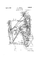
Fig. 1 is atop plan view of a trenching ma- 2@ chine.
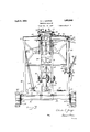
Fig. 2 is a side elevation of the machine.
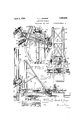
Fig. 3 is a rear end elevation partly in section and with some parts removed."
Fig. 4 is a fragmentary top plan view of the guide and frame and a portion of the digging wheel frame.
Fig. 5 is a rear elevation of the guide frame.
6 is a fragmentary elevation through the central portion of the machine showing the driving mechanism for the digging wheel.
Wheel.
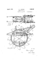
Fig. 7 is a top plan view of the digging wheel frame.
Fig. 8 is a side elevation of the digging wheel and digging wheel frame.
Fig. 9 is a front end view of the digging wheel frame showing a fragmentary section of the digging wheel and a portion of'the conswinging to one side or the other of the main p i frame so that the width of the trenchmay be varied. It will be apparent. that a wide trench may be dug by positioning the digging wh'eelat an'acute angle with respect to the main frame A, or a relatively narrow ditch may be made by arranging the wheel in line with the main frame.
Spaced above the guide frame is a sup porting frame D, which also has horizontal swinging movements. The supporting frame cooperates with the guide frame for supporting the digging wheel B, and is flexibly connected thereto by a cable arrangement which is operated by a winch to raise or lower the digging wheel. I
Power driven mechanism is provided for conjointly swinging the guide frame C in one direction and the supporting frame D in the opposite direction. The result of this movement is that the outer part of the diggingwheel B .may be swungto one side or the other of the main frame, and the inner part nearestthe main frame is moved to the opposite side. This enables the angular position of the digging wheel to be readily varied by power means. c p
For delivering theearth dug by the digging wheel B to one side, a conveyor F is positioned adjacent the wheel. The con veyor is supported at the outer end by a cable suspended from a boom, the inner end being attached to the digging wheel frame. -The machine is propelled over the ground by traction units G of the caterpillar type, and one of the units is horizontally extensible so that a relatively wide or narrow area may be spanned by the machine. Power means in the form of rack and pinion is employed to move one traction unit toward or away from the main frame. This enables the machine to operate even thoughfit has to move over a ditch of considerable width,
as in cleaning or retrenching large irrigation trenches.
Referring more particularly to the drawings, the main frame A of the machine comprises a pair of side beams 1 which are connected by cross beams 2 and suitable auxiliary braces.
In rear of the main frame is a digging wheel B, which consists of a rim 4 to the outer sides of'which a series of buckets 5 are secured. On opposite sides of the ring or rim 4; are series of gear teeth 6 which are engaged by driving gears 7 carried by opposite sides of the digging wheel frame.v
The digging wheel frame is made up of longitudinal beams 8 positioned on opposite sides of the digging wheel B and cross bars connecting the beams 8. Secured to bars 9 on the underside of the beams 8 isa rectangular frame 10, to the lower cornersof which are securedpairs of gears 11 and 12, respectively. A shield 4 secured to the front portion of the frame 10 prevents thedischarge of-earth from the buckets until they reach the conveyor F. The gears 11 and 12 mesh with the teeth 6 on the rim 4 and have in wardly spaced rollers which assist in holeingthe rim 4 in the proper position. A pair of rollers 13 above the gears 11 assist in holdingthe digging wheel, and. it
' is apparent that the rollers 13 and the inwardly spaced rollers of the gears 7, 11 and 12 support the digging wheel. I
In order to break up the earth between the buckets 5 and the surface of the ground, pairs of cuttersti and 6 are connected to opposite sides of the lower end of-therectangular frame 10. The cutter 5 is composed of a pair of blades and is directly geared to the teeth 6 of the rim 4 while the cutter 6 in advance of-the cutter has four blades and is operatively geared to the rim teeth 6 through a sprocket'and chain connection 7 The blades of the cutters are outwardly bowed at the outer ends, and these cutters loosen the earth asthe digging wheel B moves forwardly.
Rising from the front ends of the beams areibarsl l which are connected at their upper ends by a brace 14 Beams 15 incline clownwardly from the brace 14 andare' connected to the opposite ends of the side beams 8. Pairs of brackets 16 are secured to the upright bars 14i,and the brackets of each pair are vertically spaced from each other. l V'ithin each bracket 16 is a large central roller 17, and in front of the roller 17 is a pair of smaller transversely spaced rollers 18. The rollers 17 and 18 are'arranged to fit over an 2 I-beam for a purpose hereinafter described.
I The guide frame O is mounted on the main frame A and is composed of a cross bar 19 at the rear end, and extendingfrom the bar 19 are parallel side bars 20. .A'bracket 21'is connectedlto the front ends of the side bars with an upright stub shaft 22 mounted on the main frame. Rising from opposite ends of the cross bar19 are inclined uprights 22 to the upper ends of which bars 23 are secured. The bars 23 extend downwardly and forwardly, and are secured at their front ends to the bracket 21. Braces 24 connect the intermediate portions of the uprights 22 and bars 20.
A curved track 26 on the main frame extends from one side to the other and rollers 25 secured to the underside of the end portions of .the cross beam 19 are movable over the track 26. It is apparent from the above description that the carriage frame C may swing horizontally or transversely across the main frame A over the track 26 and about the stud shaft 22 as a pivot.
The upper end portions of the braces 23 of the carriage frame extend beyond the inplate 27 is pivoted to a transverse beam-28 fixed to a pair of spaced upright guides 29, in the form of I-beams, the upper ends of which extend considerably above the guide frame C. p
Secured to the rear ends of the parallel side bars 20 is a gear housing 30 which provides a support for the lower end of a vertical shaft 31 Extending across the lower portion of the uprights 29 is a plate 31 to t e rear side of which is fixed a bearing 32 for the shaft 31, and the bearing 82 rests upon and is supported by the gear housing 30. It is apparent that the upright guide beams 29 are pivotally connected to the guide frame C and are adapted to swing as a unit horizontally relatively thereto.
The digging wheel frame is vertically slidable on the upright guides 29, the rollers 17 and 18 of the brackets 16 on the digging wheel frame fitting over the beams 29. The
guide frame C may swing to one side or the digging wheel may be adjusted vertically on the guide beams 29 so as to vary the position of the digging wheel with respect to the desired depthof the trench. V t
h lounted on the front portion of the main frame A is a power unit 32 in the form of an internal combustion engine, which constitutes the sole source of power for the moving parts of the machine.
The power unit 32 is connected through a sprocket and chain 33 with a set of beveled gears 34 for operatively driving a shaft 35 I end of the vertical shaft 31 meshes with a differential 40 which has a transverse shaft 41 mounted on the vertical guide beams 29. The ends of the shaft 41 have gear and sprocket connections 42 with opposite ends of a shaft 43 on the digging wheel frame. The driving gears 7 heretofore described for the digging wheel are fast to the shaft 43.
From the above description it is apparent that power is transmitted from the power unit 32 through the sprocket and chain connection33 to the set of beveled gears 34 which transmit power to the drive shaft 35. Power is taken from the horizontal drive shaft through bevelled gears to a vertical shaft 31, which is connected to the differential 40. From the differential 40 the drive is transmitted to the digging wheel B through the sprocket and chain connection 42. The clutch 36 enables the power unit to be disconnected from the digging wheel. The above construction and arrangement is such that the guide frame C may be swung from one side to the other of the main frame without disconnecting the operative driving parts from the pewer unit 32.
Rising from the rear end portion of the main frame, is an inverted U-frame 44, which extends across the main frame from one side to the other and inclined braces 45 connect the intermediate portion of the frame 44 with the main frame. Supported on the cross bar of the frame 44 is a supporting carriage D, which is composed of a pair of side beams 46 suitably braced and connected at its rear end i by a cross bar 47 and at the front end by a cross bar 48. Intermediate the ends or the supporting frame are rollers 49 angularly disposed with respect to each other, and in engagement with the cross bar of the frame 1 44 for swinging horizontal movements therebeveled 'ear arran ement to the main power unit 32 The beveled gear arrangement 55 includes a clutch to enable the shaft to be driven in one direction or the other in orderthat the winch 51 may be rotated one direction or the other.
The supporting carriage D is connected to support the rear end portion of the digging wheel B through a cable 56 which also connects with the guide frame 0, so that the guide frame C serves to support the front end portion of the digging wheel B. One end of the cable 56 is wound around the spool 52 of the winch 51, extends rearwardly to a sheave 57 on the outer end of the carriage D and extends downwardly to a sheave 58 on the rear end portion of the digging wheel frame. From the sheave 58 the cable 56 extends forwardly to a sheave 59 secured to the forward end portion of the digging wheel frame and then upwardly over a sheave 60 secured to the upperend of the adjacent vertical guide beam 29. From the sheave 60 the cable 56 extends downwardly to a sheave 61 adjacent the sheave 59, and then extends rearwardly to a sheave 62 adjacent the sheave 58. The cable then extends upwardly to a sheave 63 on the outer end of the supporting carriage D and from the sheave 63 the cable extends around a sheave 64 also on the end portion of the supporting carriage D. The cable 56 then passes,
over an arrangement of sheaves similar to that above described, and the op-positeend is wound about the spool 51 of the winch 51.
It is manifest that thedigging wheel is supported through the digging wheelframe and flexible cable 56, the rear end portion by may be moved toward one side of the main frame, and the inner portion may be moved toward the opposite side. By so varying the angular position of the digging wheel the width of the trench may be regulated. hen the outer end portion of the diggingwheel' is moved away over to one side, arelativelywide trench can be dug, but when the digging wheel is disposed directly in line so that the axis of the wheel is substantially parallel to the main frame, a relatively narrow ditch may be dug of a size dependent uponv the width of the digging wheel buckets 5. It is apparent that by this construction and arrangemen't'a relatively small digging wheel may beutili'zed to excavate or dig a trench, the width of which may be greatly in excess of the width of the. digging wheel.
For simultaneously swinging the support-' ing carriage D in one direction or the other so that the outer or rear end portion of the digging wheelzmay be swung to one sideor the other of the main frameA, and the guide 7 frame C in a direction opposite to the direction of movement of the supporting frame D to move the inner or front end portion of the diggingv wheel B toward the opposite side of the main frame, a pair of cables, are employed, each cable being connected respectively to the supporting carriage D and guide frame C and to a winch 58.
As shown, a cable is secured at one end to an intermediate portion of the supporting carriage D, and extends about sheaves 66 arranged on one side of the machine to a winch 67 about which it is coiled several times.
' From the winch 67 the cable 65 passes about a sheave 68 on the opposite side of the machine to the guide frame C. Adjacent the winch 67 is a winch 69, about which is wound a cable 70, one end of which is secured to the opposite side of the guide frame C. From the winch 69 the cable extendsabout a sheave 71 on the adjacent side of the main frame and then across the main frame 11 to a sheave 7 2 on the opposite side. From the sheave 72 the cable 7 0 extends to the opposite side of the supporting carriage D where it is secured. Between the winchs 67 and 69 is a clutch 78, a driving shaft 74 for the winches being suitably connected to the main power unit 82. By driving one winch or the other the guide frame C is swung in one direction or the other and the supporting carriage D is conjointly moved in a direction opposite to the direction of movement of the guide frame.
For conveying the earth dug by the buckets 5 to one side of the machine and away from the excavated ditch or trench, a conveyor F extends through the diggingwheel B, and one end thereof is supported by the digging wheel frame. The conveyor consists of a frame 75 carrying a series of rollers 76, about which is trained an endless belt 77. The inner end of theframe is connected by U-bolts .78 to a tube 79 supported at its opposite ends by bearings 80 and 81 connected by bolts to elongated arcuate slots 82 and 88 respectively, formed in cross bars of the digging wheel frame. It is apparent "that the connection between the conveyor ing shaft 8% is arranged within the tube 79,
and has a sprocket and chain connection 85 with the roller at the outer end of the conveyor. The: drive shaft 81 is connected by set of bevelled in the housing 86 to the shaft as, which is driven by the main sprocket and chain connection 12'. The connection between the drive 8% and shaft position without disturbing the driving connection.
The outer end portion of the conveyor F is supported by a boom 87 flexibly connected to the conveyor by a cable 88. One end'of the cable is wound about the outer spool 53 of the digging wheel winch 51 and from the spool the cable 88 passes over a sheave 89 on the upper portion of the frame 44, and then downwardly to a sheave 90' on the inner. end of the boom 87 From the sheave 90 the cable 88 extends over a sheave 91 on the outer end of the boom, and then downwardly around a sheave 92 connected to a bail 93 which is attached to the outer end of the conveyor frame. From the sheave 92 the cable 88 extends upwardly over a sheave 94 adjacent the sheave 91, and then around a sheave 95 to a hand wheel 96. By operating,
the hand wheel 96, the conveyor may be manually raised or lowered, but in the operation of the winch 51, it is to be understood that the conveyor F is simultaneously raised or lowered with the digging wheel B.
To enable the conveyor F tobe swung outwardly or inwardly with respect to the main frame, a cable 97 is secured at one end to the inverted U-frame 14, and extends about a sheave 98 on the outer'end portion of the boom, and then forwardly to a sheave 99 on the frame tt. From the sheave 99 the cable 97 extends downwardly to handwheel 100. By operating the hand wheel 100 the outer end of the boom is moved toward or away from the main frame, so that the conveyor may be moved forwardly or rearwardly, as desired. As shown, the inner end of the boom 87 has a universal connection 101 with the frame i l.
The machine frame is propelled over the ground by caterpillar mechanism G, which consists of a relatively long traction unit 102 on one side, and a relatively short traction unit 103 on the opposite side. The detail construction of the traction units forms no part of the present invention, and it is deemed sufficient to say that the traction unit 102 has a sprocket and chain connection 108 with a shaft 104, which is suitably connected to be driven from the power'unit 82 j The mounting of the traction unit 103 is an important feature of the invention, and this traction unit is so supported and connected to the mainframe A that it may be moved away from or closer to the main frame. This enables the machine to be adapted to secure traction regardless of the width of the trench or the nature of the terrain.
The traction unit 103' has a sprocket and chain connection 105 witha driving shaft 106 having a squared portion slidable through a drivlng gear 107. The gear 107 is suitably connected to be driven from the power unit 32 and detail descr1pt1on of the connections between the gear 107 and the power unit are not considered necessary. Bymeans of the squared portion of the driving shaft 106 the shaft may slide through the driving gear 107, but continue to transmit power to the operating parts of the traction unit 103.
The main frame A is supported by a rectangular hollow beam 108, which is securely fixed to the main frame and the traction unit 102.. Telescoping inside of the supporting beam 108 is abeam 109, which is securely fastened at its outer end to the traction unit 103, and secured to the upper side of the beam 109 is a rack 110, which is disposed in an elongated opening 111 in the main supporting beam 108. Meshing with the rack is a pinion 112 fixed to a shaft 113, and operative- 1y connected to be driven from the power unit 32.
By driving the pinion 112 the traction unit 103 may be moved away from or towards the main frame A without disturbing the driving connection between the power unit 32 and the traction unit 108, as above described. The driving connection between the traction units 102 and 103, and the power unit 32 is such that the machine may be slowly propelled over the ground as the digging wheel operates to excavate a ditch or trench.
hen it is not desired to operate the digging wheel 13 and to move the machine at a more rapid rate over the ground, a clutch is provided to enable the traction units to move at a faster rate of speed. Clutches are also provided for driving one traction unit or the other alone to enable the machine to turn in one direction or the other, as will be understood. The gear arrangement and connections for effecting these results form no part of the present invention, and detail description thereof is not considered necessary.
While I have described my improved machine in more or less detail to comply with the requirements of the statute, it is, nevertheless, desired that this detailed description may be considered merely as illustrative, and not as limiting, and it is to be understood that changes and modifications may be made by those skilled in this art without departing from the invention as defined in the following claims.
What I claim as new and desire to secure by Letters Patent is:
1. In a machine of the class described, a main frame, a digging wheel, a frame for said wheel, a guide frame having a vertically disposed horizontally swingable guide, a orive shaft on said guide frame, means connecting said digging wheel and said guide for vertical movements thereon, a flexible drive between said drive shaft and said diggin wheel, a supporting carriage above said guide frame, a cable supporting connection between said supporting carriage and said digging wheel frame, and means for winding and unwinding said cable for raising or lowering said digging wheel.
2. In a machine of the class described, a main frame, a digging wheel, a frame for said wheel, a guide'f-rame pivoted at its inner end to said main frame for horizontal swinging movements and having a vertically disposed pivoted guide, means connecting said digging wheel frame and guide for enabling vertical adjustment of said digging wheel, a drive shaft on said *uide frame, a flexible connection between said drive shaft and wheel, a supporting carriage above said guide. frame and pivotally mounted at its inner end, cable means connecting respectively said supporting carriage,-guide frame and spaced portions of said digging wheel frame, means for winding and unwinding said cable for raising or lowering said digging wheel, and conjoint means for swinging said guide frame and supporting frame in opposite directions.
8. A machine of the class described comprising a mainframe, a digging wheel, a frame for said wheel, a pair of vertically spaced supporting members on said main frame, and a single cable connecting the inner and outer portions of said wheel frame with sair supporting members respectively.
l. A machine of theclass described com prising a main frame, a digging wheel, a frame for said wheel, a guide frame having a vertically disposed guide, means connecting said wheel frame to said guide for vertical movements thereon, a supporting frame above said guide frame, asingle cable for sup-' porting said wheel frame connecting respectively the outer and inner portions of said wheel with-said supporting and guide frames, and means for winding or unwinding said cable for raising or lowering said wheel.
5. A machine of the class described comprising a main frame, a digging wheel, a frame for said wheel, a guide frame having a vertically disposed horizontally movable guide, means connecting said wheel frame to said guide for vertical movements thereon, a supporting frame above said guide frame, a single cable for supporting said wheel. frame connecting respectively the outer and inner'portions of said wheel frame with-said supporting and guide frame, means for winding or unwinding said cable for raising or lowering said wheel frame, and'means for simultaneouslymoving said guide and supporting frames horizontally in opposite directions, thereby to adjust the angular position of said wheel with respect vtothe main frame. 7
6. A machine of the class described comprising a main frame, a digging wheel, a frame for said wheel,.a guide frame having a vertical guide at one end, meansfor pivotally mounting theopposite end of said guide frame for horizontal swinging movements on said main frame, means connecting said wheel frame to said guide, a supporting frame above said guide frame having a pivotal mounting at one end, cable means connecting said guide and supporting frames to said wheel frame, and means for simultaneously swinging one frame in one direction and theother frame in the opposite direction for adjusting the position of said wheel.
7. A machine of the class described com- 'prising a main frame, a digging wheel, a jframefor said wheel, supporting members on said main frame, and a single cable connecting respectively inner and outer portions of said wheel frame to said supporting members. V
8. A machine of'the class described comprising amain frame, a digging device, a frame for said digging device, a connection between said digging frame and mainframe permitting lateral swinging movements of the former relative to the latter, an endless conveyor extending laterally of said digging frame, a supporting connection between the inner end of said conveyor and said digging frame enabling limited lateral movements of said conveyor relative to said digging frame, a flexible support for the outer end of said conveyor, and means on said digging frame for driving said conveyor and adapted to be accommodated automatically to adjustment of said conveyor. 7
9. A machine of the class described comprising a main frame, a digging device comprising an endless series of buckets, a frame for said digging device, a connection between said digging frame and main frame, a belt conveyor extending laterally of said digging frame, a frame for said conveyor, a supporting connection between the inner end of said conveyor frame and said digging frame enabling limited swinging movements in a lateral direction of said conveyor frame relative to said digging frame, a flexible supporting connection for the opposite end of said conveyor frame, and means on the digging frame for driving said conveyor and adapted to be accommodated automatically to adjustment of said conveyor.
10. Amachine of the class described comprising'a main frame, a digging wheel, a frame. for said wheel, supporting members v on said main frame, a single cable connecting respectively inner and outer portions of sald wheel frame to said supporting members, an endless conveyor extending laterally of said digging frame, a supporting connection between the inner end of said conveyor and said digging frame enabling limited latprising av main frame, a digging wheel, a frame for said wheel, a pairof vertically spaced supporting frames on said main frame, means connecting said supporting frames and said digging wheel frame for enabling one supporting frame to support one part of said digging wheel and the other supporting frame to support another part of said wheel, means to impart lateralmovement to said frame in, opposite directions for angularly adjusting said Wheel, meansfor raising and lowering said digging wheel, an endless conveyor cxtendmg laterally of said diggingframe, a supporting connection between the inner end of said conveyor and l-wl
Priority Applications (1)
| Application Number | Priority Date | Filing Date | Title |
|---|---|---|---|
| US240402A US1852048A (en) | 1927-12-16 | 1927-12-16 | Trenching machine |
Applications Claiming Priority (1)
| Application Number | Priority Date | Filing Date | Title |
|---|---|---|---|
| US240402A US1852048A (en) | 1927-12-16 | 1927-12-16 | Trenching machine |
Publications (1)
| Publication Number | Publication Date |
|---|---|
| US1852048A true US1852048A (en) | 1932-04-05 |
Family
ID=22906366
Family Applications (1)
| Application Number | Title | Priority Date | Filing Date |
|---|---|---|---|
| US240402A Expired - Lifetime US1852048A (en) | 1927-12-16 | 1927-12-16 | Trenching machine |
Country Status (1)
| Country | Link |
|---|---|
| US (1) | US1852048A (en) |
Cited By (7)
| Publication number | Priority date | Publication date | Assignee | Title |
|---|---|---|---|---|
| US2451315A (en) * | 1945-06-23 | 1948-10-12 | Gar Wood Ind Inc | Digging wheel drive for trenchers |
| US2716821A (en) * | 1951-03-28 | 1955-09-06 | Jr Harry Campbell Grant | Mobile snow removing machine |
| US2894341A (en) * | 1953-10-05 | 1959-07-14 | William M Amthor | Digging machine |
| DE1116607B (en) * | 1953-04-18 | 1961-11-02 | Lauchhammer Maschb Und Stahlba | Bucket wheel for excavator |
| US3196562A (en) * | 1962-03-16 | 1965-07-27 | Vincent S Penote | Excavating machine |
| US3500563A (en) * | 1967-09-15 | 1970-03-17 | Barber Greene Co | Wheel-type top loading machine and method |
| US3702509A (en) * | 1970-09-08 | 1972-11-14 | Joseph G Zowaski | Trenching machine with tapered buckets |
-
1927
- 1927-12-16 US US240402A patent/US1852048A/en not_active Expired - Lifetime
Cited By (7)
| Publication number | Priority date | Publication date | Assignee | Title |
|---|---|---|---|---|
| US2451315A (en) * | 1945-06-23 | 1948-10-12 | Gar Wood Ind Inc | Digging wheel drive for trenchers |
| US2716821A (en) * | 1951-03-28 | 1955-09-06 | Jr Harry Campbell Grant | Mobile snow removing machine |
| DE1116607B (en) * | 1953-04-18 | 1961-11-02 | Lauchhammer Maschb Und Stahlba | Bucket wheel for excavator |
| US2894341A (en) * | 1953-10-05 | 1959-07-14 | William M Amthor | Digging machine |
| US3196562A (en) * | 1962-03-16 | 1965-07-27 | Vincent S Penote | Excavating machine |
| US3500563A (en) * | 1967-09-15 | 1970-03-17 | Barber Greene Co | Wheel-type top loading machine and method |
| US3702509A (en) * | 1970-09-08 | 1972-11-14 | Joseph G Zowaski | Trenching machine with tapered buckets |
Similar Documents
| Publication | Publication Date | Title |
|---|---|---|
| US1852048A (en) | Trenching machine | |
| US799753A (en) | Excavator. | |
| US1762569A (en) | Ditching machine | |
| US2052372A (en) | Pipe line uncovering means | |
| US1762568A (en) | Ditch-digging machine | |
| US1347860A (en) | Excavating and granding machine | |
| US1337184A (en) | Cable-laying machine | |
| US1733427A (en) | Excavator | |
| US1717476A (en) | Ditch-digging machine | |
| US1850363A (en) | Trench excavator construction | |
| US2846786A (en) | Mobile ditching machine | |
| US1501621A (en) | Ditching machine | |
| US2140823A (en) | Roadside trencher | |
| US1573125A (en) | Automatic loader | |
| US1472562A (en) | Grading and excavating machine | |
| US2527415A (en) | Terracing machine | |
| US1892525A (en) | Trenching machine | |
| US1246524A (en) | Multiple-wheel trench-machine. | |
| US2598350A (en) | Auger type trenching machine | |
| US1817367A (en) | Trench tractor | |
| US1842193A (en) | Swinging conveyer trencher | |
| US3772807A (en) | Excavator for graves and the like | |
| US1316999A (en) | Ditching-machine | |
| US1907373A (en) | Excavating machine | |
| US3530599A (en) | Elevating belt loader and excavation apparatus |