US185151A - Improvement in grain-binders - Google Patents
Improvement in grain-binders Download PDFInfo
- Publication number
- US185151A US185151A US185151DA US185151A US 185151 A US185151 A US 185151A US 185151D A US185151D A US 185151DA US 185151 A US185151 A US 185151A
- Authority
- US
- United States
- Prior art keywords
- wheel
- rake
- shaft
- grain
- lever
- Prior art date
- Legal status (The legal status is an assumption and is not a legal conclusion. Google has not performed a legal analysis and makes no representation as to the accuracy of the status listed.)
- Expired - Lifetime
Links
- 239000011230 binding agent Substances 0.000 title description 12
- 241001589086 Bellapiscis medius Species 0.000 description 20
- 210000001847 Jaw Anatomy 0.000 description 16
- 238000010276 construction Methods 0.000 description 4
- 230000013707 sensory perception of sound Effects 0.000 description 4
- 210000000707 Wrist Anatomy 0.000 description 2
- 230000000875 corresponding Effects 0.000 description 2
Images
Classifications
-
- A—HUMAN NECESSITIES
- A01—AGRICULTURE; FORESTRY; ANIMAL HUSBANDRY; HUNTING; TRAPPING; FISHING
- A01D—HARVESTING; MOWING
- A01D37/00—Reaper-binders
- A01D37/06—Reaper-binders binding with stalks or straw bands
Definitions
- my invention consists in the construction and arrangement of a grain-rake and binder, as will be hereinafter more fully set forth.
- FIG. l is a plan view of my improved grain-rake and binder.
- Fig. 2 is a side or end elevation, and Fig. 3 a rear elevation, of the same.
- Fig. 4 is a front view of a part of the machine.
- Fig. 5 is a perspective view of the rake-carriage.
- Fig. 6 is a perspective view of a four-armed catcher used in the machine.
- Fig. 7 represents the twister.
- Fig. 8 shows a combined cog and cam-wheel used in the machine.
- A represents the frame-work of the machine; B, the cutter-bar; and O the slat-platform, upon which the grain falls.
- the grain is carried by the rake from the platform 0 up an incline, D, and falls over projecting arms E E onto the binding-table G.
- a slotted or double track, H running below, but parallel with the platform 0 and incline D, and a suitable distance above, and parallel with, said track is a bar, I, as shown in Fig. 3.
- a carriage, J On the track H is a carriage, J, provided at each end with a stud or pin and roller, a, which projects into the slot in the track.
- the carriage J is supported on the track by wheels I) b at each end, and held by aroller or wheel, (1, arranged to bear against the under side of the track.
- a rod, K In suitable bearings on the carriage is placed a rod, K, which passes under the platform 0, and is provided with a series of rake-teeth, L L, to pass up between the slats of the platform, said rod and teeth forming the rake for conveying the grain from the platform up the incline to the binding-table.
- a coilspring Around the rod K, near its rear end, is a coilspring, 0, so arranged that its tendency is to throw and hold the teeth L down below the platform, a stop, f, attached to the rod, preventing the teeth from going down too far.
- a lever, M On the rear end of the rod K is a lever, M, in the same plane as the rake-teeth, which lever is used to hold the teeth up when raised, by means of a spring-latch, h, entering a slot, 1;, in the upper end of the lever, said springlatch being arranged on a slotted standard, n, on the carriage J, as shown in Fig. 5.
- 0 represents the main driving-wheel of the machine, provided with an internal cog-gear, k, which meshes with a pinion, m, secured on a shaft, "n, and this, by means of bevel-gears p p, communicates motion to a line-shaft, P, from which both the rake and the binder are operated.
- a toothed wheel, R On the rear end of the shaft P is secured a toothed wheel, R, which is to be connected by an endless chain with a similar wheel, S, on the outer end of a shaft, 4", passing through, and having its hearings in, the bar I a suitable distance from its upper end.
- a toothed wheel, T On the inner or front end of the shaft 4 is another toothed wheel, T, around which passes an endless chain, 8, and this chain passes under two idle toothed pulleys, t t, at the angle of the bent bar I, and around a toothed wheel, U, near the outer end of said bar I.
- crank or wrist, c which extends into a vertically-slotted standard, V, on the rake-carriage J.
- the teeth L are held in upright position by the lever M, having been caught upon or by the spring-latch h entering the slot '0' therein.
- the rake moves along the platform, and up the incline, carrying the grain with it, the carriage moving upon the double or slotted track H.
- the latch h is withdrawn by means of a stationary finger, w, attached to the bar I.
- the spring a would then at once throw the rake-teeth down below the slats of the incline, but at the same time as the latch h is being withdrawn, the lower end of the lever M comes against another finger, .90, also attached to said bar 1, so that as the carriage continues to advance or ascend to the top of the incline, the rake-teeth are throw'n'forward so as to push the grain over the top of the incline D and upon the arms E, over which it slides down onto the binding-table.
- the rake then commences to descend, and as soon as the lever M clears the finger x the spring 6 turns the rake-teeth over and below the surface of the incline.
- WVhen the rakecarriage J arrives near the outer end of the track a springhook, y, catches upon a pin, 2, projecting from the lever M, and gradually lifts the same into a vertical position, thereby raising the rake-teeth, so that when the rod K is at the extreme outer end the teeth will be in proper position for work, they being then held by the spring-latch h having entered the slot 1' in the upper end of the lever M.
- a vertically-standing rake, W moves forward from under the arms E and pushes the entire bundle past the verticallyoperating needle Y.
- the rake W is composed of vertical teeth at tached to a horizontal frame or head provided with rollers a), upon which it moves on the binding-table.
- the rake-head is further provided with avstud and roller, b working'in a slot, d, in the table to guide the movement of the rake back and forth.
- the wheel B is rotated by means of a pinion, W, on the end of the shaft 1?, meshing with cogs a formed on the outer periphery around the inner edge of the wheel.
- the needle Y moves in suitable guides p attached to an arm, 0, extending over the binding-table; and the needle is operated by means of a lever, D, pivoted on top of said arm, and having its inner or rear end slotted, and fitting over a stud, 'r, on the needle.
- the outer or front end of the lever D is also slotted, and placed over a stud, 8 on the upper end of a bar, E, sliding vertically in suitable guides.
- This bar is also slotted, and passes over the axle or shaft of the wheel B, and to the bar are pivoted two arms, G G, one above and one below said wheel-shaft, and extending in opposite directions, the outer ends of said arms being slotted and placed over stationary pins or arms 15 t, as seen in Fig. 4.
- These arms G G are actuated by means .of a cam, 'v, on the outer or front side of the wheel B, for raising and lowering the needle at the proper times.
- a cogged segment, w On the periphery of the wheel B is a cogged segment, w, which meshes with a pinion, 00 on a shaft, y, at intervals or intermittently.
- a bevel cog-wheel, H On the inner end of the shaft y is a bevel cog-wheel, H, which gears with a corresponding pinion, (If, on a vertical shaft, N, that carries the twister.
- This twister consists of two L-shaped arms, I, pivoted to the upper end of the shaft b and surrounded by a collar, J, which is pressed upward by means of a spring, 01 to close the arms or jaws I I. When the collar J is pressed downward an interposed spring, 0', opens said jaws.
- collar J is surrounded by a loose ring, f pivoted in the arms ofa forked lever, K, said lever being pivoted to the frame-work under the binding-table, and its outer end is slotted and operated by one end of a crank-shaft, L, entering said slot, this shaft having a crank on each end.
- the crank on the outer end of .shaft L bears against the periphery of the wheel B to hold the collar J down, and in the periphery of said wheel is formed a recess, h so that when this part of the wheel gets opposite the crank on the outer end of the shaft L the spring at under the collar J will force the same upward to close the twister, the shaft L turning in its hearings to accommodate such movement.
- a projecting pin On the inner side of the wheel B is a projecting pin, i which, once during each revolution of said wheel, strikes a four-armed wheel, M, secured on the end of a shaft, N, and thus turns said shaft one-fourth of a revolution.
- the shaft N by means of gears It 70 communicates said motion to another shaft, P.
- the thread-catcher On this shaft the thread-catcher is secured, which is constructed as follows: 0 O are four curved wings secured on the shaft P, andon said shaft is further secured a fourarmed wheel, R, as shown in Fig. 6.
- the Wings 0 are hollow, and in the end of each wing, directly opposite each arm of the wheel R, is pivoted a jaw, S, pressed by means of a spring, at, against said arm.
- Each jaw S is, at its inner or pivoted end, provided with an arm,p which extends through the wing O, and has a roller, 10?, upon its projecting end.
- the entire cord -catcl1er makes onefourth of a revolution for each revolution of the wheel B, bringing successively the four arms with their jaws in position to receive the cord, the jaws being opened by the rollers n working against a stationary cam, T, secured to the frame of the machine under the binding-table.
- a collar, 8 On the intermittently rotating shaft y, which operates the twister, is a collar, 8 provided with a slot on one side, and into this slot takes a spring-pawl, t, for holding the shaft y stationary, and preventing the twister from rotating.
- an arm, 0- which is actuated, by means of a cam
- the spring-pawl t has w, on the inner side of the wheel B, to raise the pawl out of the notched collar just at the time when the cogged segment to is about to engage with the pinion :10 for rotating the shaft 3 and through it the twister.
- the grain is first moved forward past the needle, to allow the cord to pass in to the twister, and the moment the cord is in between the jaws of the twister saidjaws close and gripe the cord, and then start the 1.
- the combination with the slotted track H, of the carriage J, having rollers a, b, and d, and carrying the rake K L, and provided with the slotted standard V, the toothed wheels S and U, the idle toothed pulleys t t, and the endless chain s, provided with the crank 11, all substantially as and for the purposes herein set forth.
- the rake W constructed as described, provided with curved arms V and rollers 01, and b and operated by means of the lever Z, arm A, spring 7?, roller c and cam f on the wheel B, substantially as and for the purposes herein set forth.
Description
5 Sheets-Sheet 1. E. R. WHITNEY.
GRAIN-BINDER.
Patented Dec. 5.,
ATTORNEYS THE GRAPH [C CO. NA-
5Sheets-Sheet 2. E. R. WHITNEY.
GRAIN-BINDER. NQ 185,151 Patented Dec. 5,1876.
WITNESS INVENTOR yz/wwjww 63 0% Q we M. M
ATTORNEYS THE GRAPHIC CONX 5 Sheets-Sheet 3.
E. R. WHITNEY. GRAIN-BINDER.
. j WITNESSES INVENTOR I ATTQRNEYS THE GRAPH 1C CO-NX '5 Sheets-Shejet 5...
E.'R. WHITNEY.
INVENTOR ATTORNEYS THE GRAPHIC ID-NA- TED EDWIN R. WHITNEY, OF MAGOG, QUEBEC, CANADA.
IMPROVEMENT m GRAIN-BINDERS.
Specification forming part of Letters Patent N 0. 185, 15!, dated December 5, 1876; application filed October 11, 1876.
To all whom it may concern:
Be it known that I, EDWIN RUTHVEN WHITNEY, of Magog, in the county of Stanstead, Province of Quebec, and in the Dominion' ofOanada, have invented certain new and useful Improvements in Grain-Binder and Bake; and do hereby declare that the following is a full, clear, and exact description thereof, reference being had to the accompanying drawings and to the letters of reference marked thereon, making a part of this specification.
The nature of my invention consists in the construction and arrangement of a grain-rake and binder, as will be hereinafter more fully set forth.
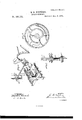
In order to enable others skilled in the art to which my invention appertains to make and use the same, I will now proceed to describe its construction and operation,referrin g to the annexed drawings, in which- Figure l is a plan view of my improved grain-rake and binder. Fig. 2 is a side or end elevation, and Fig. 3 a rear elevation, of the same. Fig. 4 is a front view of a part of the machine. Fig. 5 is a perspective view of the rake-carriage. Fig. 6 is a perspective view of a four-armed catcher used in the machine. Fig. 7 represents the twister. Fig. 8 shows a combined cog and cam-wheel used in the machine.
A represents the frame-work of the machine; B, the cutter-bar; and O the slat-platform, upon which the grain falls. The grain is carried by the rake from the platform 0 up an incline, D, and falls over projecting arms E E onto the binding-table G. At the back of the machine is a slotted or double track, H, running below, but parallel with the platform 0 and incline D, and a suitable distance above, and parallel with, said track is a bar, I, as shown in Fig. 3.
On the track H is a carriage, J, provided at each end with a stud or pin and roller, a, which projects into the slot in the track. The carriage J is supported on the track by wheels I) b at each end, and held by aroller or wheel, (1, arranged to bear against the under side of the track. In suitable bearings on the carriage is placed a rod, K, which passes under the platform 0, and is provided with a series of rake-teeth, L L, to pass up between the slats of the platform, said rod and teeth forming the rake for conveying the grain from the platform up the incline to the binding-table. Around the rod K, near its rear end, is a coilspring, 0, so arranged that its tendency is to throw and hold the teeth L down below the platform, a stop, f, attached to the rod, preventing the teeth from going down too far. On the rear end of the rod K is a lever, M, in the same plane as the rake-teeth, which lever is used to hold the teeth up when raised, by means of a spring-latch, h, entering a slot, 1;, in the upper end of the lever, said springlatch being arranged on a slotted standard, n, on the carriage J, as shown in Fig. 5.
0 represents the main driving-wheel of the machine, provided with an internal cog-gear, k, which meshes with a pinion, m, secured on a shaft, "n, and this, by means of bevel-gears p p, communicates motion to a line-shaft, P, from which both the rake and the binder are operated.
On the rear end of the shaft P is secured a toothed wheel, R, which is to be connected by an endless chain with a similar wheel, S, on the outer end of a shaft, 4", passing through, and having its hearings in, the bar I a suitable distance from its upper end. On the inner or front end of the shaft 4 is another toothed wheel, T, around which passes an endless chain, 8, and this chain passes under two idle toothed pulleys, t t, at the angle of the bent bar I, and around a toothed wheel, U, near the outer end of said bar I.
To the chain 8 is firmly fastened a crank or wrist, c, which extends into a vertically-slotted standard, V, on the rake-carriage J.
As the rake is carrying the grain from the outer end of the platform, the teeth L are held in upright position by the lever M, having been caught upon or by the spring-latch h entering the slot '0' therein. In this position the rake moves along the platform, and up the incline, carrying the grain with it, the carriage moving upon the double or slotted track H. As the carriage approaches the upper end of said track the latch h is withdrawn by means of a stationary finger, w, attached to the bar I. The spring a would then at once throw the rake-teeth down below the slats of the incline, but at the same time as the latch h is being withdrawn, the lower end of the lever M comes against another finger, .90, also attached to said bar 1, so that as the carriage continues to advance or ascend to the top of the incline, the rake-teeth are throw'n'forward so as to push the grain over the top of the incline D and upon the arms E, over which it slides down onto the binding-table.
The rake then commences to descend, and as soon as the lever M clears the finger x the spring 6 turns the rake-teeth over and below the surface of the incline. WVhen the rakecarriage J arrives near the outer end of the track a springhook, y, catches upon a pin, 2, projecting from the lever M, and gradually lifts the same into a vertical position, thereby raising the rake-teeth, so that when the rod K is at the extreme outer end the teeth will be in proper position for work, they being then held by the spring-latch h having entered the slot 1' in the upper end of the lever M. As soon as the grain has been deposited on the binding-table G a vertically-standing rake, W, moves forward from under the arms E and pushes the entire bundle past the verticallyoperating needle Y.
The rake W is composed of vertical teeth at tached to a horizontal frame or head provided with rollers a), upon which it moves on the binding-table. The rake-head is further provided with avstud and roller, b working'in a slot, d, in the table to guide the movement of the rake back and forth. To the back of the rake W, in the center, is pivoted one end of a lever, Z, the other end of which is pivoted to the frame-work of the machine. To this lever Zis attached an arm, A, which has its end bent outward, and provided with a roller, 0 and this roller bears against a mum), formed on the side of a large wheel, B, the arm A being actuated by means of aspring, h, as shown in Fig. 1; As the wheel B revolves, the cam f, at the proper time, actnates the arm A, so as to move the rake W forward the requisite distance; and, as soon as the cam passes off from the roller e, the spring h at once draws the rake back to its former position. The arm A is guided in its movement by a stud, with roller 6 working in a slot, 70, in the table G. The wheel B is rotated by means of a pinion, W, on the end of the shaft 1?, meshing with cogs a formed on the outer periphery around the inner edge of the wheel. The needle Y moves in suitable guides p attached to an arm, 0, extending over the binding-table; and the needle is operated by means of a lever, D, pivoted on top of said arm, and having its inner or rear end slotted, and fitting over a stud, 'r, on the needle. The outer or front end of the lever D is also slotted, and placed over a stud, 8 on the upper end of a bar, E, sliding vertically in suitable guides. This bar is also slotted, and passes over the axle or shaft of the wheel B, and to the bar are pivoted two arms, G G, one above and one below said wheel-shaft, and extending in opposite directions, the outer ends of said arms being slotted and placed over stationary pins or arms 15 t, as seen in Fig. 4. These arms G G are actuated by means .of a cam, 'v, on the outer or front side of the wheel B, for raising and lowering the needle at the proper times. On the periphery of the wheel B is a cogged segment, w, which meshes with a pinion, 00 on a shaft, y, at intervals or intermittently. On the inner end of the shaft y is a bevel cog-wheel, H, which gears with a corresponding pinion, (If, on a vertical shaft, N, that carries the twister. This twister consists of two L-shaped arms, I, pivoted to the upper end of the shaft b and surrounded by a collar, J, which is pressed upward by means of a spring, 01 to close the arms or jaws I I. When the collar J is pressed downward an interposed spring, 0', opens said jaws. The
collar J is surrounded by a loose ring, f pivoted in the arms ofa forked lever, K, said lever being pivoted to the frame-work under the binding-table, and its outer end is slotted and operated by one end of a crank-shaft, L, entering said slot, this shaft having a crank on each end. The crank on the outer end of .shaft L bears against the periphery of the wheel B to hold the collar J down, and in the periphery of said wheel is formed a recess, h so that when this part of the wheel gets opposite the crank on the outer end of the shaft L the spring at under the collar J will force the same upward to close the twister, the shaft L turning in its hearings to accommodate such movement.
On the inner side of the wheel B is a projecting pin, i which, once during each revolution of said wheel, strikes a four-armed wheel, M, secured on the end of a shaft, N, and thus turns said shaft one-fourth of a revolution. The shaft N, by means of gears It 70 communicates said motion to another shaft, P. On this shaft the thread-catcher is secured, which is constructed as follows: 0 O are four curved wings secured on the shaft P, andon said shaft is further secured a fourarmed wheel, R, as shown in Fig. 6. The Wings 0 are hollow, and in the end of each wing, directly opposite each arm of the wheel R, is pivoted a jaw, S, pressed by means of a spring, at, against said arm. Each jaw S is, at its inner or pivoted end, provided with an arm,p which extends through the wing O, and has a roller, 10?, upon its projecting end. The entire cord -catcl1er makes onefourth of a revolution for each revolution of the wheel B, bringing successively the four arms with their jaws in position to receive the cord, the jaws being opened by the rollers n working against a stationary cam, T, secured to the frame of the machine under the binding-table. On the intermittently rotating shaft y, which operates the twister, is a collar, 8 provided with a slot on one side, and into this slot takes a spring-pawl, t, for holding the shaft y stationary, and preventing the twister from rotating. an arm, 0- which is actuated, by means of a cam,
The spring-pawl t has w, on the inner side of the wheel B, to raise the pawl out of the notched collar just at the time when the cogged segment to is about to engage with the pinion :10 for rotating the shaft 3 and through it the twister.
When the grain drops over the arms E E down onto the binding-table, it falls on two curved arms, V V, projecting forward from the rake W, said rake then moving the grain against the cord which passes from the spool W through the needle down to the four-armed cord'catcher. After the grain is passed far enough past the needle, the needle descends and the four-armed cord-catcher turns onefourth around, opens, and passes over the point of the needle and holds the cord tight,
. while the twister starts to revolve and cuts off the cord just as it starts to revolve, when the rake W moves back and the needle-ascends with the end of the cord always held in the four-armed catcher. As the rake W conimences its return movement the curved arms V pull the sheaf back a little, sufficient to allow the cord to be twisted under.
It will be seen that the grain is first moved forward past the needle, to allow the cord to pass in to the twister, and the moment the cord is in between the jaws of the twister saidjaws close and gripe the cord, and then start the 1. The combination, with the slotted track H, of the carriage J, having rollers a, b, and d, and carrying the rake K L, and provided with the slotted standard V, the toothed wheels S and U, the idle toothed pulleys t t, and the endless chain s, provided with the crank 11, all substantially as and for the purposes herein set forth.
2. The rake K L, coiled spring 6, lever M, with sloti and projecting pin 2, and the springlatch h, in combination with the stationary fingers w w on the track H, and the springhook y on the side of the frame, all constructed and operating substantially as and for the purposes herein set forth.
3. The rake W, constructed as described, provided with curved arms V and rollers 01, and b and operated by means of the lever Z, arm A, spring 7?, roller c and cam f on the wheel B, substantially as and for the purposes herein set forth.
4. The combination of the vertical needle Y, guides 19, slotted lever D, the vertical slotted slide E, arms G G, and the cam v on the wheel B, substantially as and for the purposes herein set forth.
5. The combination of the intermittentlyrotating shaft 1?, wings O, four-armed wheel R, pivoted jaws S with springs m and arms '19, with rollers n and the stationary cam T,
all substantially as and for the purposes herein set forth.
6. The combination of the wheel B with projecting pin 1 the f'ourarmed wheel M, shaft N, gears 10 W, and the shaft P, with four-armed cord-catcher attached thereto, substantially as and for the purposes herein set forth.
7. The combination of the intermittentlyrotating shaft '2, slotted collar 8 spring-pawl 15 with arm '0 and the cam 10 on the wheel B, substantially as and for the purposes herein set forth.
In testimony that I claim the foregoing I have hereunto set my hand this 11th day of September, 1876. Y
- E. R. WHITNEY.
Witnesses:
A. M. NAUGHTON, D. M. NAUGHTON.
Publications (1)
| Publication Number | Publication Date |
|---|---|
| US185151A true US185151A (en) | 1876-12-05 |
Family
ID=2254556
Family Applications (1)
| Application Number | Title | Priority Date | Filing Date |
|---|---|---|---|
| US185151D Expired - Lifetime US185151A (en) | Improvement in grain-binders |
Country Status (1)
| Country | Link |
|---|---|
| US (1) | US185151A (en) |
-
0
- US US185151D patent/US185151A/en not_active Expired - Lifetime
Similar Documents
| Publication | Publication Date | Title |
|---|---|---|
| US185151A (en) | Improvement in grain-binders | |
| US219433A (en) | Improvement in grain-binders | |
| US188162A (en) | Improvement in grain-binders | |
| US190936A (en) | Improvement in grain-binders | |
| US107797A (en) | Daniel moeherspjt | |
| US167997A (en) | Improvement in grain-binders | |
| US269332A (en) | Grain-binding harvester | |
| US506711A (en) | Self-binding harvester | |
| US254879A (en) | lottridge | |
| US101040A (en) | Improvement in machine for picking cranberries | |
| US19958A (en) | Improvement in raking attachments to harvesters | |
| US85210A (en) | Improvement in grain-binders | |
| US468295A (en) | grieser | |
| US253705A (en) | Harvesting-machine | |
| US341131A (en) | Grain-binder | |
| US77878A (en) | Improvement in grain-binders | |
| US452980A (en) | mcdonald | |
| US378225A (en) | Grain-binder | |
| US181954A (en) | Improvement in grain-binders | |
| US260668A (en) | Mechanism | |
| US318953A (en) | Grain | |
| US240440A (en) | mclein | |
| US297357A (en) | Harvester | |
| US259328A (en) | Grain-binder | |
| US186186A (en) | Improvement in grain-binders |