US185145A - Improvement in smoke-stacks and spark-arresters - Google Patents
Improvement in smoke-stacks and spark-arresters Download PDFInfo
- Publication number
- US185145A US185145A US185145DA US185145A US 185145 A US185145 A US 185145A US 185145D A US185145D A US 185145DA US 185145 A US185145 A US 185145A
- Authority
- US
- United States
- Prior art keywords
- smoke
- spark
- stack
- stacks
- arresters
- Prior art date
- Legal status (The legal status is an assumption and is not a legal conclusion. Google has not performed a legal analysis and makes no representation as to the accuracy of the status listed.)
- Expired - Lifetime
Links
- 210000003128 Head Anatomy 0.000 description 8
- 238000010276 construction Methods 0.000 description 6
- 238000002485 combustion reaction Methods 0.000 description 4
- 239000002184 metal Substances 0.000 description 4
- 241000282619 Hylobates lar Species 0.000 description 2
- 239000003818 cinder Substances 0.000 description 2
- 230000003292 diminished Effects 0.000 description 2
- 239000000428 dust Substances 0.000 description 2
- 230000000694 effects Effects 0.000 description 2
- 230000000266 injurious Effects 0.000 description 2
- 239000000314 lubricant Substances 0.000 description 2
- 230000004048 modification Effects 0.000 description 2
- 238000006011 modification reaction Methods 0.000 description 2
- 230000003472 neutralizing Effects 0.000 description 2
Images
Classifications
-
- B—PERFORMING OPERATIONS; TRANSPORTING
- B01—PHYSICAL OR CHEMICAL PROCESSES OR APPARATUS IN GENERAL
- B01F—MIXING, e.g. DISSOLVING, EMULSIFYING OR DISPERSING
- B01F35/00—Accessories for mixers; Auxiliary operations or auxiliary devices; Parts or details of general application
- B01F35/45—Closures or doors specially adapted for mixing receptacles; Operating mechanisms therefor
- B01F35/451—Closures or doors specially adapted for mixing receptacles; Operating mechanisms therefor by rotating them about an axis parallel to the plane of the opening
Definitions
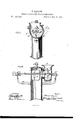
- Figure 1 of the drawings is a re1. resentation of a side view, part sectional, of my smokestack and spark-arrester.
- Fig. 2 is a central vertical sectional view of the same.
- This invention relates to devices attached to the smoke-stacks of steanrengines for arresting and extinguishing sparks; and it consists, mainly, in the employment of a rotating fan and discharging-receiver, which together operate to extinguish said sparks. It also consists in making the shaft of said fan hollow, so that air may pass through the same and cool it. It also consists in making cross-perforations through the arms which support said shaft, for the same purpose. It also consists in various subsidiary devices, arrangements, and combinations, hereinafter particularly set forth.
- A designates the stack-head of a'steam-engine. Said stack-head is closed at the top, but has a side outlet, B, near its upper end, through which the products of combustion pass.
- 0 designates a cylindrical casing, having a flaring mouth on its circumference, and provided with an annular flange, 0, whereby it is swiveled upon or within a similar flange, b, surrounding outlet B, and forming part of smoke-stack head A.
- Casing 0 receives and discharges the sparks, which pass up through the smoke-stack and opening B.
- a pipe may be attached to the flaring mouth 0 of said casing or receiver; but this is not always necessarygis the fan, hereinafter described, in conjunction with said casing, will extinguish all the sparks that pass up through the smoke-stack.
- F designates two upwardly-curving metal arms, which are secured by their lower ends to smoke-stack head A, on opposite sides thereof, and are provided at their upper ends with clips or supportingblocks 1?, which bear sleeves or cylindrical bearings F
- sleeves or cylindrical bearings rotates a hollow shaft, G, whichpa-sses through stack-head A and easing or receiver 0, and is provided with a rotating fan, H, inside of said casing.
- Said shaft is also provided with adjustable stop-collars I, which prevent it from passing too far longitudinally in either direction through said cylindrical bearings, and with a fixed belt-wheel or pulley, J, whereby it is rotated.
- the power may be applied through a belt from the driving-shaft of the engine.
- each supporting-arm F is preferably made hollow, for the sake of lightness.
- the upper part of each of said supporting-arms is transversely perforated at f f, to allow the passage of air through it, and thus cool it when heated.
- the hollow construction of shaft G answers the same purpose.
- the friction between said shaft and its bearings may also be diminished by'the use of lubricants or anti-friction metal.
- the air-admitting construction described is also useful in neutralizing the injurious effects of the great heat communicated to the smoke-stack and its attachments by the continually-ascending currents of the products of combustion.
- Opening B may be closed at will by means of a sliding valve or cut-oft plate, K, which conforms to the interior face ofstack-head A,
- crank or belt wheel may be substituted
- a gear-wheeler its equivalent may be substituted for the pulleyor belt-wheel on fan-shaft G.
- Variousother modifications may be made without departing from the spirit and scope ofmy'invention.
- stack-head A having opening B, substantially as and for thepurposes set forth.
Description
J'. TAYLOR. SMOKE-STACK AND SPARK-ARRESTER. N o 1 8 5 1 4 5 Q Pate nte d D e c. 5,. 18 76.
INVENTOR. 0%5073 ATTORN'EYS.
THE GRAPHIC CO-N-Y- WITNESSES JAMES TAYLOR, or NEVADA, OHIO.
IMPROVEMENT IN SMOKE-STACKS AND SPARK-ARRESTERS.
Specification forming part of Letters Patent No. 185,145, dated December 5, 1876; application filed October 28, 1876.
To all whom "it may concern:
Be it known that I, JAMES TAYLOR, of Nevada, in the county of Wyandot and State of Ohio, have invented a new and valuable Improvement in Smoke-Stacks and Spark-Arresters; and I do hereby declare that the following is a full, clear, and exact description of the construction and operation of the same, reference being had to the annexed drawings, making a part of this specification, and to the letters and figures of reference marked thereon.
Figure 1 of the drawings is a re1. resentation of a side view, part sectional, of my smokestack and spark-arrester. Fig. 2 is a central vertical sectional view of the same.
This invention relates to devices attached to the smoke-stacks of steanrengines for arresting and extinguishing sparks; and it consists, mainly, in the employment of a rotating fan and discharging-receiver, which together operate to extinguish said sparks. It also consists in making the shaft of said fan hollow, so that air may pass through the same and cool it. It also consists in making cross-perforations through the arms which support said shaft, for the same purpose. It also consists in various subsidiary devices, arrangements, and combinations, hereinafter particularly set forth.
In the annexed drawings, A designates the stack-head of a'steam-engine. Said stack-head is closed at the top, but has a side outlet, B, near its upper end, through which the products of combustion pass. 0 designates a cylindrical casing, having a flaring mouth on its circumference, and provided with an annular flange, 0, whereby it is swiveled upon or within a similar flange, b, surrounding outlet B, and forming part of smoke-stack head A. Casing 0 receives and discharges the sparks, which pass up through the smoke-stack and opening B. As indicated in dotted lines, Fig. 1, it may be turned up or down at any angle desired, and there locked by means of a clamping-00L lar, D, which surrounds flanges b and c. Said collar is divided transversely at opposite points, and is provided at these openings with screw-tapped lugs d d d 61. Through lugs d d, on opposite sides of one of these openings, passes a short screw, 6, which merely serves to hold the sections of said collar together.
Through the opposite lugs, d 01, passes the screw-threaded end of an adjusting-rod, E, which has a small head orthumb-piece, E. By turning this rod in one direction, the sections of collar D are drawn closely together, clamping casing or receiver 0 in the position which it then occupies; By turning it in the other direction, said collar is loosened, so that said casing or discharging-receiver may be turned into any other position desired.
If preferred, a pipe may be attached to the flaring mouth 0 of said casing or receiver; but this is not always necessarygis the fan, hereinafter described, in conjunction with said casing, will extinguish all the sparks that pass up through the smoke-stack.
F designates two upwardly-curving metal arms, which are secured by their lower ends to smoke-stack head A, on opposite sides thereof, and are provided at their upper ends with clips or supportingblocks 1?, which bear sleeves or cylindrical bearings F In said sleeves or cylindrical bearings rotates a hollow shaft, G, whichpa-sses through stack-head A and easing or receiver 0, and is provided with a rotating fan, H, inside of said casing. Said shaft is also provided with adjustable stop-collars I, which prevent it from passing too far longitudinally in either direction through said cylindrical bearings, and with a fixed belt-wheel or pulley, J, whereby it is rotated. The power may be applied through a belt from the driving-shaft of the engine. The lower part of each supporting-arm F is preferably made hollow, for the sake of lightness. The upper part of each of said supporting-arms is transversely perforated at f f, to allow the passage of air through it, and thus cool it when heated. The hollow construction of shaft G answers the same purpose. The friction between said shaft and its bearings may also be diminished by'the use of lubricants or anti-friction metal. The air-admitting construction described is also useful in neutralizing the injurious effects of the great heat communicated to the smoke-stack and its attachments by the continually-ascending currents of the products of combustion.
The sparks, passing into casing or receiving-chamber G, are dashed against the inner face thereof by fan H until they are entirely for said bevel-pinion.
extinguished, when they escape in the form of cinders and dust from outlet 0;
Opening B may be closed at will by means of a sliding valve or cut-oft plate, K, which conforms to the interior face ofstack-head A,
and which is operatedby acrank, L, on an uprightshaft, M, that passes upward through the top of stack-head A. .Said shaft is provided, above said stackhead, with .a beveL V -pinion,ll, whereby it receives partial rotary motion through suitable gearing adapted to" be operated by the engineer or other attendant.
A crank or belt wheel may be substituted Also, a gear-wheeler its equivalent may be substituted for the pulleyor belt-wheel on fan-shaft G. Variousother modifications may be made without departing from the spirit and scope ofmy'invention.
What I claim as new, and desire to secure by Letters Patent, is r '1. In a spark arrester and extinguisher, the combination of a rotating fan with a casing or spark-receiver,surrounding the same, and with V a smoke-stack head, opening into said casing, the opening being closed at will by a sliding valve or cutofiplate, which: conforms to'the interior face of the smoke-stack, substantially as set forth.
2. In a spark-arrester, thesp'ark-receiver G, r
provided with an annular flange, c, in combination with the smoke-stack, having flange b V and clamping-collar D, divided. transversely, and provided with screw-tapped lugs d d and screw 'e,whereby the spark-receiver is circuin- V ierentially'turned and held in any desired po-' sition, substantially as described, and for the purpose set forth.
3. In a spark-'arrest'er, the hollow shaft G, 7 provided with stop-collars I I, in combination with the perforated supportingarins FF, hav
ing clips F1 13 and sleeves F substantially as described, and for the purpose set forth.
1 V r 4. In a sparkearrester, the combination of cut-off or valve K with crank L,.shaft M, and
stack-head A, having opening B, substantially as and for thepurposes set forth.
In testimony that I claim the above I have hereunto subscribed my name in the presence of two witnesses.
' JAMES TAYLOR.
Witnesses:
JOHN F. ACKER, Jr., (L'H. MOEWEN.
Publications (1)
| Publication Number | Publication Date |
|---|---|
| US185145A true US185145A (en) | 1876-12-05 |
Family
ID=2254550
Family Applications (1)
| Application Number | Title | Priority Date | Filing Date |
|---|---|---|---|
| US185145D Expired - Lifetime US185145A (en) | Improvement in smoke-stacks and spark-arresters |
Country Status (1)
| Country | Link |
|---|---|
| US (1) | US185145A (en) |
Cited By (1)
| Publication number | Priority date | Publication date | Assignee | Title |
|---|---|---|---|---|
| US2877724A (en) * | 1954-07-07 | 1959-03-17 | Sanicom Company Inc | Draft inducers for boilers |
-
0
- US US185145D patent/US185145A/en not_active Expired - Lifetime
Cited By (1)
| Publication number | Priority date | Publication date | Assignee | Title |
|---|---|---|---|---|
| US2877724A (en) * | 1954-07-07 | 1959-03-17 | Sanicom Company Inc | Draft inducers for boilers |
Similar Documents
| Publication | Publication Date | Title |
|---|---|---|
| DE1557157A1 (en) | Device for cleaning exhaust gas using an electrostatic precipitator | |
| US185145A (en) | Improvement in smoke-stacks and spark-arresters | |
| US229207A (en) | William m | |
| US768255A (en) | Spark-arrester. | |
| US934479A (en) | Spark-arrester. | |
| US214676A (en) | Improvement in smoke-condenser and spark-extinguisher | |
| US787454A (en) | Ventilating and air-cooling mechanism. | |
| US374987A (en) | peichaed | |
| US134796A (en) | Improvement in flue-blasts for steam fire-engines | |
| US114846A (en) | Improvement in spark-arresters | |
| US374562A (en) | John h | |
| US227272A (en) | Smoke-stack | |
| US944043A (en) | Chimney cowl or ventilator. | |
| US1322768A (en) | Spark-arrester | |
| US1175870A (en) | Spark-arrester and smoke-purifier. | |
| US145596A (en) | Improvement in spark-arresters | |
| US260564A (en) | Hermann hahn | |
| US572558A (en) | To the | |
| US997761A (en) | Spark-arrester. | |
| US876417A (en) | Spark-arrester. | |
| US1125727A (en) | Spark-arrester. | |
| US246048A (en) | veeity | |
| US972637A (en) | Fume-arrester and smoke-purifier. | |
| US604264A (en) | Thawing apparatus | |
| US819079A (en) | Fan-blower. |