US185122A - Improvement in elevated railways - Google Patents
Improvement in elevated railways Download PDFInfo
- Publication number
- US185122A US185122A US185122DA US185122A US 185122 A US185122 A US 185122A US 185122D A US185122D A US 185122DA US 185122 A US185122 A US 185122A
- Authority
- US
- United States
- Prior art keywords
- girder
- wheels
- car
- improvement
- rails
- Prior art date
- Legal status (The legal status is an assumption and is not a legal conclusion. Google has not performed a legal analysis and makes no representation as to the accuracy of the status listed.)
- Expired - Lifetime
Links
- 229910000831 Steel Inorganic materials 0.000 description 4
- XEEYBQQBJWHFJM-UHFFFAOYSA-N iron Chemical compound [Fe] XEEYBQQBJWHFJM-UHFFFAOYSA-N 0.000 description 4
- 239000000203 mixture Substances 0.000 description 4
- 230000000630 rising Effects 0.000 description 4
- 239000010959 steel Substances 0.000 description 4
- 229910000754 Wrought iron Inorganic materials 0.000 description 2
- 230000001808 coupling Effects 0.000 description 2
- CWYNVVGOOAEACU-UHFFFAOYSA-N fe2+ Chemical compound [Fe+2] CWYNVVGOOAEACU-UHFFFAOYSA-N 0.000 description 2
- 230000005484 gravity Effects 0.000 description 2
- 229910052742 iron Inorganic materials 0.000 description 2
- 230000004301 light adaptation Effects 0.000 description 2
- 239000000463 material Substances 0.000 description 2
Images

Classifications
-
- B—PERFORMING OPERATIONS; TRANSPORTING
- B61—RAILWAYS
- B61B—RAILWAY SYSTEMS; EQUIPMENT THEREFOR NOT OTHERWISE PROVIDED FOR
- B61B13/00—Other railway systems
- B61B13/04—Monorail systems
Definitions
- My improvement consists, rst, in a girder for elevated railways constructed with vertical and horizontal projecting anges to adapt it to support a car projecting laterally on one side only of the said girder, so that by. a duplication of parts a single girder may be made to support on its respective sides cars moving in opposite directions.
- My improvement consists, secondly, in a combination of rails and wheels, the former being above and on the side of the girder, and the latterI consisting of wheels with horizontal axes to rest on the upper and lower rails, and of wheels having vertical axes to resist the lateral strain of the overhung car.
- M y invention consists, thirdly, in constructing an elevated-railway girder hollow, so that it may serve as a pneumatic tube.
- the engine and boiler are so placed as to come as much as possible over the supportingway. They are made compact, so as to occupy but little width, the longitudinal room being abundant, while in other directions space cannot be readily spared.
- Figure I is a transverse sectional V.View through the girder, and showing the eTid elevation of one carriage and a transverse sectionof the other.
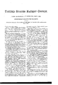
- Fig. 2 is a partial side elevation, and part longitudinal vertical section.
- the column A has a form to obtain the lightness consistent with the re- 'lhe height will vary with the position and purpose. In cities the height would be sufficient to enable the ordinary traffic to pass beneath it at the crossings. In country districts so great a height in some cases might not be necessary.
- a long tube, the interior ot' which is hollow, as shown in cross-section, and may be :of such form as to render it available as a tube for pneumatic transport.
- the girder B Upon the sides ot' the girder B are projecting flanges b b, which support the rails b b', on which traverse the principal wheels c c of the car.
- On the upper part of the girder are rising flanges b b, which form rails on which traverse the upper supportingwheels c c of the car.
- the permanent way is so contrived, and the carriages are so constructed and hung, that the former answers for two tracks to be traversed by carriages going in opposite directions. rIhis subserves a number of purposes, especially saving ot' room in thoroughtares, and saving of' cost of permanent way.
- the girder B may be made of several sections bolted together. rIhe sections may have a joint in a vertical or in a horizontal plane. rlhe tubular interior may consist of one, two, or more chambers to afford opportunity jfor pneumatic dispatch in two dierent directions simultaneously. The divisional piece is shown in dotted lines in Fig. l.
- the feet ot' the timber posts in the ground may be embedded in a mass of concrete, which will harden and form a base to prevent lateral swaying.
- the tubular girder may be used as a watermain for town, or a gas-main for towns, or for sewerage or drainage purposes for high levels.
- the girder-tubes may be Wrought or cast. In either case thestructure possesses the important qualification of combined strength and lightness in the greatest possible degree the material admits of, in addition to its adaptation to furnish, by itsV interior, additional means of transit. y
- the supporting-posts or trestle-work may be wrought-iron tubes, the ends having iron blocks cast thereon.
- the tube itself may have sliding couplings at thejoints to allow for expansion and contraction from change of temperature.
- Wheels z z, Fig. 1 are attached to the carriage, and run beneath the lateral rails, so as to prevent the rising of the car, and its consequent running from the track.
- a Fig. 2 is a side View ofa portion of the permanent way, and one of the cars in position.
- the girder B is supported by diagonal braces from the pillar A.
- the three sets oi' wheels are seen in side elevation.
- the upper wheels c are shown running upon the top flanges b of the girder, and the horizontally-rotating wheel c" running against the side ofthe said flange.
- the carriage is driven by a steam-engine.
- the weight of the engine and boiler is disposed as nearly as possible over the wheels c. rlhe kind I prefer to use is one of my own invention.
- the said engine is the subject-matter of United States Patent No. 108,718, issued to me October 25, 1870, and need not be particularly described in this place.
- r1 ⁇ he pitman is connected at its upper end to the piston-head, and at its lower end to the crank-axle ofthe wheel.
- the vertical form and has the usual accessories.
- the car is preferably ot' steel, for purposes ofstrength and lightness.
- the boiler is of liar necessity for lightness in this connection. llhe permanent way may be lighter if the rolling-stock be all of steel.
- the rolling-stock itself being much lighter without deterioration of strength the proportion ot' the deadweight to the freight-carrying capacity is much less.
- the amount of power required to move it is lessened, which is of especial importance in this case where the motor is required to occupy but small space, and that, perhaps, in a somewhat unusual position.
- Fig. 1 I have shown the boiler and engineat one end of the carriages.
- a girder, B for elevated railways, constructed with vertical and horizontal projecting fianges to adapt it to support a car projecting' laterally on one side only ot' the said girder, so that by a duplication ofparts a single gil-der may be made to support on its respective sides cars moving in opposite directions, substantially as described.
- a continuous tube or hollow girder in an elevated railway possessing the two functions ot a road-bed or support for independent lines for transit in opposite directions, and also as a tube for pneumatic transport, as described.
Description
FI G2.
Na.1a5,1zz.
MONTGMERY.
THE GRAPHIC CUJLY 2 Sheets-SheetZ.
tented Dc.5, 1876.
INVENT OR A quired strength.
JAMES MONTGOMERY, OE LIVINGSTON, NEW YORK.
IMPROVEMENT IN ELEVAT-ED RAILWAYS.
Spccilicationl forming part of Letters Patent No. 185, R224, dated December 5,1876; application `filed May 25,1870.
To all whom it may concern: y
Be it known that I, J AMES MONTGOMERY, of Livingston, i-n the county of Columbia and State of New York, have invented Improvements in Elevated Railways and Carri-ages therefor, ot' which the following is a specification:
My improvement consists, rst, in a girder for elevated railways constructed with vertical and horizontal projecting anges to adapt it to support a car projecting laterally on one side only of the said girder, so that by. a duplication of parts a single girder may be made to support on its respective sides cars moving in opposite directions.
i My improvement consists, secondly, in a combination of rails and wheels, the former being above and on the side of the girder, and the latterI consisting of wheels with horizontal axes to rest on the upper and lower rails, and of wheels having vertical axes to resist the lateral strain of the overhung car. y
M y invention consists, thirdly, in constructing an elevated-railway girder hollow, so that it may serve as a pneumatic tube.
'Ihe carriage is made relativelylong and narrow, so as to decrease the leverage incident to its Overhanging position.
The engine and boiler are so placed as to come as much as possible over the supportingway. They are made compact, so as to occupy but little width, the longitudinal room being abundant, while in other directions space cannot be readily spared.
Figure I is a transverse sectional V.View through the girder, and showing the eTid elevation of one carriage and a transverse sectionof the other. Fig. 2 is a partial side elevation, and part longitudinal vertical section.
Arepresents the central supporting-column, the section cutting transversely through the longitudinal girder and the foot-flange of one of the supports. The column Ahas a form to obtain the lightness consistent with the re- 'lhe height will vary with the position and purpose. In cities the height would be sufficient to enable the ordinary traffic to pass beneath it at the crossings. In country districts so great a height in some cases might not be necessary. In some cases infact, a long tube, the interior ot' which is hollow, as shown in cross-section, and may be :of such form as to render it available as a tube for pneumatic transport. Upon the sides ot' the girder B are projecting flanges b b, which support the rails b b', on which traverse the principal wheels c c of the car. On the upper part of the girder are rising flanges b b, which form rails on which traverse the upper supportingwheels c c of the car. On theinside faces of' the said ilanges b b traverse other4 car-wheels, c c, which rotate in a horizontal lplane,and act as stays to bear the lateral drag of the car due to its overhanging character, the center of gravity being outside of the line of support upon the rails b b.
' One of the wheels c is driven directly by the engine, the wheels c and c" being merelyA supporting and traversing wheels, not directly driven by the motor. r y
The permanent way is so contrived, and the carriages are so constructed and hung, that the former answers for two tracks to be traversed by carriages going in opposite directions. rIhis subserves a number of purposes, especially saving ot' room in thoroughtares, and saving of' cost of permanent way.
The girder B may be made of several sections bolted together. rIhe sections may have a joint in a vertical or in a horizontal plane. rlhe tubular interior may consist of one, two, or more chambers to afford opportunity jfor pneumatic dispatch in two dierent directions simultaneously. The divisional piece is shown in dotted lines in Fig. l.
The feet ot' the timber posts in the ground may be embedded in a mass of concrete, which will harden and form a base to prevent lateral swaying.
The tubular girder may be used as a watermain for town, or a gas-main for towns, or for sewerage or drainage purposes for high levels.
The girder-tubes may be Wrought or cast. In either case thestructure possesses the important qualification of combined strength and lightness in the greatest possible degree the material admits of, in addition to its adaptation to furnish, by itsV interior, additional means of transit. y
The supporting-posts or trestle-work may be wrought-iron tubes, the ends having iron blocks cast thereon.
The tube itself may have sliding couplings at thejoints to allow for expansion and contraction from change of temperature.
Wheels z z, Fig. 1, are attached to the carriage, and run beneath the lateral rails, so as to prevent the rising of the car, and its consequent running from the track.
A Fig. 2 is a side View ofa portion of the permanent way, and one of the cars in position.
It Will be seen that the girder B is supported by diagonal braces from the pillar A. The three sets oi' wheels are seen in side elevation. To the axle of one of the principal Wheels vc the pitman of the engine H is connected. The upper wheels c are shown running upon the top flanges b of the girder, and the horizontally-rotating wheel c" running against the side ofthe said flange.
The carriage is driven by a steam-engine. The weight of the engine and boiler is disposed as nearly as possible over the wheels c. rlhe kind I prefer to use is one of my own invention. Y
The said engine is the subject-matter of United States Patent No. 108,718, issued to me October 25, 1870, and need not be particularly described in this place.
r1`he pitman is connected at its upper end to the piston-head, and at its lower end to the crank-axle ofthe wheel.
the vertical form, and has the usual accessories.
The car is preferably ot' steel, for purposes ofstrength and lightness. There is a pecu- The boiler is of liar necessity for lightness in this connection. llhe permanent way may be lighter if the rolling-stock be all of steel. The rolling-stock itself being much lighter without deterioration of strength the proportion ot' the deadweight to the freight-carrying capacity is much less. The amount of power required to move it is lessened, which is of especial importance in this case where the motor is required to occupy but small space, and that, perhaps, in a somewhat unusual position.
In Fig. 1 I have shown the boiler and engineat one end of the carriages.
I claim- 1. A girder, B, for elevated railways, constructed with vertical and horizontal projecting fianges to adapt it to support a car projecting' laterally on one side only ot' the said girder, so that by a duplication ofparts a single gil-der may be made to support on its respective sides cars moving in opposite directions, substantially as described.
2. The described combination of rails and wheels, the former being above' and on the side of the girder, and the latter consisting of wheels with horizontal axes to rest on the upper and lower rails, and of Wheels having vertical axes to resist the lateral strain of the over-hung car, as and for the purpose described.
3. A continuous tube or hollow girder in an elevated railway possessing the two functions ot a road-bed or support for independent lines for transit in opposite directions, and also as a tube for pneumatic transport, as described.
JAMES MONTGOMERY.
Publications (1)
| Publication Number | Publication Date |
|---|---|
| US185122A true US185122A (en) | 1876-12-05 |
Family
ID=2254527
Family Applications (1)
| Application Number | Title | Priority Date | Filing Date |
|---|---|---|---|
| US185122D Expired - Lifetime US185122A (en) | Improvement in elevated railways |
Country Status (1)
| Country | Link |
|---|---|
| US (1) | US185122A (en) |
Cited By (1)
| Publication number | Priority date | Publication date | Assignee | Title |
|---|---|---|---|---|
| US4233904A (en) * | 1977-10-21 | 1980-11-18 | Waggon Union Gmbh | Asymmetrical subway vehicle |
-
0
- US US185122D patent/US185122A/en not_active Expired - Lifetime
Cited By (1)
| Publication number | Priority date | Publication date | Assignee | Title |
|---|---|---|---|---|
| US4233904A (en) * | 1977-10-21 | 1980-11-18 | Waggon Union Gmbh | Asymmetrical subway vehicle |
Similar Documents
| Publication | Publication Date | Title |
|---|---|---|
| US185122A (en) | Improvement in elevated railways | |
| US354558A (en) | Elevated railway | |
| US468841A (en) | George a | |
| US421820A (en) | Rail for elevated ways | |
| US1034840A (en) | Monorail railway. | |
| US173240A (en) | Improvement in elevated railways | |
| US1306225A (en) | Elevated kailway | |
| US157385A (en) | Improvement in endless-rope traction-railways | |
| US262126A (en) | Construction of cable railways | |
| US199901A (en) | Improvement in wire-rope railway-tubes | |
| US116059A (en) | Improvement in railways | |
| US345645A (en) | Elevated railroad | |
| US255235A (en) | babbitt | |
| US555921A (en) | Elevated railway | |
| US245876A (en) | Apparatus for moving houses | |
| US786874A (en) | Elevated railroad. | |
| US507402A (en) | Railway system | |
| US386779A (en) | Railway traction device | |
| US148238A (en) | Improvement in street-railways | |
| US1196717A (en) | Overhead railway. | |
| US415991A (en) | zipernowsky | |
| US268586A (en) | Method of propelling cars | |
| US214937A (en) | Improvement in elevated-railway car and track | |
| US466364A (en) | Elevated-street-railway car and truck | |
| US277039A (en) | Bridge |