US185120A - Improvement in belt-shifters - Google Patents
Improvement in belt-shifters Download PDFInfo
- Publication number
- US185120A US185120A US185120DA US185120A US 185120 A US185120 A US 185120A US 185120D A US185120D A US 185120DA US 185120 A US185120 A US 185120A
- Authority
- US
- United States
- Prior art keywords
- belt
- pulley
- shifters
- plate
- lever
- Prior art date
- Legal status (The legal status is an assumption and is not a legal conclusion. Google has not performed a legal analysis and makes no representation as to the accuracy of the status listed.)
- Expired - Lifetime
Links
- 238000010586 diagram Methods 0.000 description 2
- 230000004048 modification Effects 0.000 description 2
- 238000006011 modification reaction Methods 0.000 description 2
- 230000002441 reversible Effects 0.000 description 2
- 230000013707 sensory perception of sound Effects 0.000 description 2
- 230000035939 shock Effects 0.000 description 2
Images

Classifications
-
- D—TEXTILES; PAPER
- D06—TREATMENT OF TEXTILES OR THE LIKE; LAUNDERING; FLEXIBLE MATERIALS NOT OTHERWISE PROVIDED FOR
- D06F—LAUNDERING, DRYING, IRONING, PRESSING OR FOLDING TEXTILE ARTICLES
- D06F37/00—Details specific to washing machines covered by groups D06F21/00 - D06F25/00
- D06F37/30—Driving arrangements
- D06F37/36—Driving arrangements for rotating the receptacle at more than one speed
Definitions
- FREDERICK B MILES, OF PHILADELPHIA, PENNSYLVANIA, ASSIGNOR TO HIMSELF AND OSCAR O. FERRIS, OF PLACE.
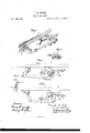
- Figure 1 is a perspective view of my improved belt-shifting device for metal-planing machines; Figs. 2 and 3, plan views, showing the device in different positions; Fig. 4., a vertical section on the line 1 2; and Fig. 5, a diagram illustrating a modification of my invention.
- A is part of the reciprocating table of a planing-machine, from the bed B of which project the two brackets D and E.
- a on the bracket E, is loosely hung a plate, G, in which is a slot, composed of two segmental parts, a and 00, both being concentric with the pivot-pin a, but the part as being more distant than the part .12 from the center of the said pin, and the two parts of the slot communicating with each other at y, where there is an abrupt step.
- the belt-shifters consist of two bell-crank levers, H and H, the lever H having a long arm, I), and a short arm, d, and the lever H a long arm, I), and short' arm d, the long arm of each lever having at its outer end an eye for the passage of the belt.
- the pivot-pins e e of the two levers have their hearings in the bracket E, and pins f f on the short arms of the two levers project through the slots in the plate G.
- the planing-machine has the usual three pulleys, M, N, and N, (shown by dotted lines,) the central pulley M being fast on the shaft and the others loose.
- Two adjustable studs, m and n, are secured to the edge of the table A, the former for striking a projection, 12, on the short arm of the lever J, and the latter for striking the projection g at the extreme end of the same arm of the lever, the longarm of which is connected to the plate G by a rod, K.
- a rod, K As seen in Fig.
- the table A has just completed its movement in the direction of the arrow, during which movement the cutting takes place, and the straight belt, owing to the vibration of the plate G on its pivot, has been moved by the shifter H from the pulley N to the fast pulley M, and the i-rossed belt from the latter pulley to the pulley N, so that the table will at once commence its course in a direction contrary to that pointed out by the arrow, and will continue this course until the stud n strikes the end of the lever J, when the moving parts will assume the position shown in Fig.
- the pins ff are within the limits of the portion .90 of the slot, which looks both levers.
- the shifting-levers when in the position Fig. 2, are within the limit of, and are locked by, the portion 0a of the slot.
- .It is only essential that the slot should consist of two segmental parts, when it is made in an intermittently-vibratin g plate, G, for which the plate shown in Fig. 5 may be substituted.
- This plate may be arranged toslidein ways, and may be actuated from studs on the table, in a manner which will readily suggest itself to those skilled in the art.
Description
F. B. MILES.
BELTSHIFTER.
Patented Dec.5,1876.
THE GRAPHIC CQ-NX UNITED STATES PATENT GFrroE.
FREDERICK B. MILES, OF PHILADELPHIA, PENNSYLVANIA, ASSIGNOR TO HIMSELF AND OSCAR O. FERRIS, OF PLACE.
IMPROVEMENT IN BELT-SHIFTERS.
Specification forming part of Letters Patent No. 185,120, dated December 5, 1876; application filed August 17, 1876.
To all whom it may concern:
Be it known that l, FREDERICK B. MILEs, of Philadelphia, Pennsylvania, have invented an Improved Belt-Shifting Device for Metal- Planing Machines, of which the following is a specification The object of my invention is to construct a cheap, simple, and efi'ective belt-shifting device for reversing the motion of a planing-machine table.
In the accompanying drawing, Figure 1 is a perspective view of my improved belt-shifting device for metal-planing machines; Figs. 2 and 3, plan views, showing the device in different positions; Fig. 4., a vertical section on the line 1 2; and Fig. 5, a diagram illustrating a modification of my invention.
A is part of the reciprocating table of a planing-machine, from the bed B of which project the two brackets D and E. To a pivot-pin, a, on the bracket E, is loosely hung a plate, G, in which is a slot, composed of two segmental parts, a and 00, both being concentric with the pivot-pin a, but the part as being more distant than the part .12 from the center of the said pin, and the two parts of the slot communicating with each other at y, where there is an abrupt step.
The belt-shifters consist of two bell-crank levers, H and H, the lever H having a long arm, I), and a short arm, d, and the lever H a long arm, I), and short' arm d, the long arm of each lever having at its outer end an eye for the passage of the belt. The pivot-pins e e of the two levers have their hearings in the bracket E, and pins f f on the short arms of the two levers project through the slots in the plate G.
The planing-machine has the usual three pulleys, M, N, and N, (shown by dotted lines,) the central pulley M being fast on the shaft and the others loose. There is also the usual pair of driving-belts, one being straight to move the table in one direction, and the other crossed to move the table in the contrary direction. Two adjustable studs, m and n, are secured to the edge of the table A, the former for striking a projection, 12, on the short arm of the lever J, and the latter for striking the projection g at the extreme end of the same arm of the lever, the longarm of which is connected to the plate G by a rod, K. As seen in Fig. 2, the table A has just completed its movement in the direction of the arrow, during which movement the cutting takes place, and the straight belt, owing to the vibration of the plate G on its pivot, has been moved by the shifter H from the pulley N to the fast pulley M, and the i-rossed belt from the latter pulley to the pulley N, so that the table will at once commence its course in a direction contrary to that pointed out by the arrow, and will continue this course until the stud n strikes the end of the lever J, when the moving parts will assume the position shown in Fig. 3, the straight belt being moved from the tight pulley M to the loose pulley N, and the crossed belt from the loose pulley Nv to the fast pulley, so that the table will at once commence its return or cutting movement. It should be understood, however, that the movement of the two belt shifters is not simultaneous. When the stud m strikes the lever J, the pin f of the shifting-lever H is the first to come under the influence of the abrupt step y at the junction of the two segmental parts of the slot in the plate G, and consequently the belt on the fast pulley will be moved clear of the same by the shifter H onto the loose pulley N before the shifter H moves the other belt onto the fast pulley. Precisely the same thing occurs when the parts are moved from the position shown in Fig. 3 to that shown in Fig. 2, the tight pulley being, in all cases, freed from the influence of one belt before it is influenced by the other belt; hence there can be no such shocks or jars when the reversal of the table takes place as would occur if the two belts exercised temporary contradictory efforts on the fast pulley.
When the shifting-levers are in the position shown in Fig. l, the pins ff are within the limits of the portion .90 of the slot, which looks both levers. In like manner the shifting-levers, when in the position Fig. 2, are within the limit of, and are locked by, the portion 0a of the slot. .It is only essential that the slot should consist of two segmental parts, when it is made in an intermittently-vibratin g plate, G, for which the plate shown in Fig. 5 may be substituted. This plate may be arranged toslidein ways, and may be actuated from studs on the table, in a manner which will readily suggest itself to those skilled in the art. The
7 two parts of the slot for receiving the pins f f of the belt-shifters will, in this case, be
straight, but out of line with each other, and
communicating at an abrupt step, 3 The results accomplished by this intermittently-reciprocating plate and its slot will be precisely the same as those due to the movement of the slotted vibrating plate G, described above.
I claim as my invention- Witnesses:
HENRY HowsoN, J r., HARRY SMITH.
Publications (1)
| Publication Number | Publication Date |
|---|---|
| US185120A true US185120A (en) | 1876-12-05 |
Family
ID=2254525
Family Applications (1)
| Application Number | Title | Priority Date | Filing Date |
|---|---|---|---|
| US185120D Expired - Lifetime US185120A (en) | Improvement in belt-shifters |
Country Status (1)
| Country | Link |
|---|---|
| US (1) | US185120A (en) |
-
0
- US US185120D patent/US185120A/en not_active Expired - Lifetime
Similar Documents
| Publication | Publication Date | Title |
|---|---|---|
| US185120A (en) | Improvement in belt-shifters | |
| US758081A (en) | Belt-shipper for pulleys. | |
| US1721956A (en) | Washing machine | |
| US3077845A (en) | Control system for a sewing machine | |
| US234802A (en) | Thomas peat | |
| US2993388A (en) | Drive mechanism | |
| US1047003A (en) | Mechanical movement. | |
| US1283625A (en) | Belt-shifting mechanism. | |
| US496000A (en) | Mechanical movement | |
| US2387283A (en) | Washing machine drive | |
| US214842A (en) | Improvement in belt-shifting mechanisms | |
| US1893038A (en) | Oscillation limit device | |
| US274094A (en) | Lebbeus b | |
| US530471A (en) | Sewing-machine | |
| US1686657A (en) | Washing machine | |
| US158173A (en) | Improvement in belt-shifters | |
| US1118059A (en) | Feed-actuating mechanism for sewing-machines. | |
| US724431A (en) | Operating means for washing-machines. | |
| US1122025A (en) | Looper-operating mechanism for sewing-machines. | |
| US148353A (en) | Improvement in belt-shifters | |
| US1001053A (en) | Automatic belt-shifter. | |
| US891788A (en) | Washing-machine. | |
| US959009A (en) | Toy. | |
| US418384A (en) | Belt-shifting device | |
| US307835A (en) | Governor for steam-engines |