US1851182A - Oven - Google Patents
Oven Download PDFInfo
- Publication number
- US1851182A US1851182A US140270A US14027026A US1851182A US 1851182 A US1851182 A US 1851182A US 140270 A US140270 A US 140270A US 14027026 A US14027026 A US 14027026A US 1851182 A US1851182 A US 1851182A
- Authority
- US
- United States
- Prior art keywords
- shelf
- oven
- handle
- same
- lever
- Prior art date
- Legal status (The legal status is an assumption and is not a legal conclusion. Google has not performed a legal analysis and makes no representation as to the accuracy of the status listed.)
- Expired - Lifetime
Links
- 230000007246 mechanism Effects 0.000 description 97
- 241000287828 Gallus gallus Species 0.000 description 21
- 230000003028 elevating effect Effects 0.000 description 12
- 230000001276 controlling effect Effects 0.000 description 6
- 238000010411 cooking Methods 0.000 description 5
- 230000008901 benefit Effects 0.000 description 3
- 230000000881 depressing effect Effects 0.000 description 3
- XEEYBQQBJWHFJM-UHFFFAOYSA-N Iron Chemical compound [Fe] XEEYBQQBJWHFJM-UHFFFAOYSA-N 0.000 description 2
- 230000009471 action Effects 0.000 description 2
- 230000005540 biological transmission Effects 0.000 description 2
- 230000000994 depressogenic effect Effects 0.000 description 2
- 230000004048 modification Effects 0.000 description 2
- 238000012986 modification Methods 0.000 description 2
- 229910000831 Steel Inorganic materials 0.000 description 1
- 230000006978 adaptation Effects 0.000 description 1
- 238000005452 bending Methods 0.000 description 1
- 235000008429 bread Nutrition 0.000 description 1
- 239000003245 coal Substances 0.000 description 1
- 229940000425 combination drug Drugs 0.000 description 1
- 230000006835 compression Effects 0.000 description 1
- 238000007906 compression Methods 0.000 description 1
- 238000010276 construction Methods 0.000 description 1
- 238000010586 diagram Methods 0.000 description 1
- 239000000945 filler Substances 0.000 description 1
- 235000013305 food Nutrition 0.000 description 1
- 235000013882 gravy Nutrition 0.000 description 1
- 229910052742 iron Inorganic materials 0.000 description 1
- 239000000696 magnetic material Substances 0.000 description 1
- 230000009347 mechanical transmission Effects 0.000 description 1
- 239000000203 mixture Substances 0.000 description 1
- 230000001105 regulatory effect Effects 0.000 description 1
- 230000000284 resting effect Effects 0.000 description 1
- 230000000717 retained effect Effects 0.000 description 1
- 230000007480 spreading Effects 0.000 description 1
- 239000010959 steel Substances 0.000 description 1
Images


Classifications
-
- F—MECHANICAL ENGINEERING; LIGHTING; HEATING; WEAPONS; BLASTING
- F24—HEATING; RANGES; VENTILATING
- F24C—DOMESTIC STOVES OR RANGES ; DETAILS OF DOMESTIC STOVES OR RANGES, OF GENERAL APPLICATION
- F24C15/00—Details
- F24C15/16—Shelves, racks or trays inside ovens; Supports therefor
Definitions
- My invention relates to improvements in ovens and more particularly has reference to and is illustrated in the accompanying drawings in its application to an automatic culinary oven, such as may be used in gas, 011,
- the socalled automatic character of the oven consists in means for regulating or adjusting the oven-shelf or bottom from the outside of the "I oven, so as to avoid the necessity of stooping or bending and peering and reaching into the oven to get at the cooking, thereby frequently burning the hands, arms, and kitchen'linen, especially in withdrawing the cooking for attention, and returning same into the oven. Frequently a roast or broil is dropped on the floor.
- an adjustable oven shelf should be projectable as well as elevatable, otherwise the same annoyances and dangers remain toa largeextent, and in providing for both'movements, the oven must remain unobstructed at all times, otherwise this loss of service will defeat the utility of the oven.
- it must be easy to operate and foolproof, requiring practically no attention.
- the mechanism should be covered to avoid possible accidents, and the mechanism of one oven should not interfere with the mechanism of any other oven in the same range or stove.
- the elevation of the shelf must be of substantial amount to permit use of the bottom of the oven and the shelf at the same time, and the projection of the shelf or bottom must be for substantially the entire depth of the same to provide fullest accessibility to the contents thereof.
- the oven should be properly lined as usual, and the shelf should be open for the circulation of heat, and should at all times be rigidly secured at all four corners to insure against tilting, canting, or wabbling.
- the oven shelf should be convertible as a broiler and pan holder for use also in a broiling oven where the pan beingconsiderably below the broiling flame will not scorch, burn, or become, incrustated, and the mechanism should be adaptable to ovens of different sizes with the least possible changes.
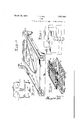
- Fig. 1 is a perspective view, parts being broken away, illustrating a suitable form of elevating and projecting mechanism, embodying an application of my invention.
- Fig.2 is a perspective view, partly-broken away, illustrating a suitable form of slide mo bearing shown in Fig. 1.
- Fig. 3 illustrates in perspective, parts being broken away, a preferred form of elevatin mechanism adapted for use at one side of the oven.
- Fig. 4 illustrates in vertical cross-section a suitable form of clutch mechanism and control handle.
- Fig. 5' is a side view ofthe lower part thereof, looking from right to left.
- Fig. 6 is a perspective view of the upper part of the clutch fork shown in Fig. 4.
- Fig. 7 illustrates in perspective part of the clutch mechanism shown in Fig. 4.
- Fig. 8 is a view looking from right to left thereat.
- Fig. 9 is a detail, partly in cross section, of the handle mechanism.
- Fig. 10 is a perspective view, parts being broken away, illustrating a modified form of shelf for lifting and sliding movement.
- Fig. 11 is a diagrammatic view of electrical connections for operating the shelf electrically.
- Fig. 12 is a perspective view, parts being broken away, and parts omitted, illustrating an arrangement for electrically projecting and elevating the shelf.
- Fig. 13 is a perspective view of gas valve locking arrangement.
- Fig. 14 is a perspective view illustrating a broiler and support therefor in combination with an adjustable oven shelf, and
- 15 and 16 indicate plates preferably of steel, and preferably of about one-sixteenth to one-eighth inch thickness which serve as the side lining of the oven, being preferably suitably secured at the top and bottom thereof in any suitable manner. These plates preferably serve as supporting means for the elevating and projecting mechanism, and also as a guide for the movement of the same.
- 17 indicates a shaft preferably behind the front frame of the oven and below the bottom thereof forward of the burner, in connection with which the elevating and sliding mechanism is preferably driven
- 18 indicates a vertical shaft at the back and at one side within the corner of the oven in connection with which the projecting mechanism is operated.
- This shaft 18 is preferably flat sided with round ends, the top and bottom being provided with suitable bearings such as 19, as shown.
- the ends of the drive shaft 17 are referably supported upon opposite walls 0 the oven and may also pass through and be additionally supported by the hanger plate or lining 16, and upon this shaft 17 are suitably mounted sleeves or tubes, which together with the shaft, control the movement of certain operating levers, as hereinafter described.
- the elevating and projecting mechanism for the shelf is for the most part duplicated preferably behind the lining and at each side of the oven, and for this reason, and to simplify the description, it will only be necessary in most instances to refer to one complete side mechanism such as illustrated. 20.
- a link 30 At the pivotal connection between the links 28 and 29, is pivotally secured a link 30, the other end of which is pivotally connected to the link 31 which is secured upon the shaft 17 so that upon rotating said shaft the links 28 and 29 are brought into alignment or pushed backwardly, as shown in the drawings, thereby raising or lowering the rack 25, which in turn rotates the pinions 24, 24 oppositely, and the arms of these pinions being pivotally connected by links to the channel guides 20, 21', raise and lower the same equally and simultaneously'.
- channel guides 20 to 21" Upon the channel guides 20 to 21" are secured base channels 32, 32, and above the same are secured other channels 33, 33.
- the angles 34, 34 upon which are mounted and equally spaced four sets of wheels or washers 35 and pinions 36 free to rotate thereon.
- the upwardly projecting edge of the channel 32 is toothed as indicated at 37 to provide a rack for engaging the pinions 36, and the oppositely projecting edge of an upper channel 38 is also provided with teeth 39, also for engaging pinions 36.
- apron 41 Upon the inner faces or sides of the upper toothed channels 38 are secured strips 40, 40, which serve as the sides of the shelf or frame which is preferably grid-like or open-work, to allow the heat to pass therethrough, and the front portion is preferably dropped down forming an apron 41, as shown, so that when the shelf is all the way down in the oven and projected entirely within the oven, the apron 41 meets .the top of the front frame at the bottom of the oven, forming a step or ledge above the bottom of the oven, the upper part of which continues back into the oven serving as a superposed oven bottom until the same has been lifted to serve as a shelf.
- pins 89 enter the holes 90 slightly" in ad-;
- said handle being pivotally secured at 92, upon the shaftor rod 81, it depresses the cup-like end 93 of the inner tube 7 8 against the action of the spring 94, the lower end of which engages the cup-like portion 93 at 95, as shown, and the upper end of which'penetrates the shaft 81 at 96, thus tending to keep the inner tube 7 8 projected upwardly against the-handle 91, but when said handle is pulled to or pushed away from the operator, its flanged base 97 overcomes the action of the spring 94 by distending the same and forcing the inner sleeve 7 8 downwardly, thereby pushing down the clutch member 7 7 and disengaging the tooth 7 9 thereof from the pinion 69, at the same time the fork 78 of said clutch member in moving down releases the cone 86, which under influence of the spring 87 allows the toothed disc 88 to engage the pinion 69, thereby locking said pinion against rotation and holding the oven shelf in its elevated position, from which it will
- the outer tube 65, 65' of the handle mechanism is provided with a handle 98, which normally extends laterally behind the lever mechanism.
- this handle 98 is gripped and pulled from the back to the right or left side around the lever mechanism.
- the handle 98 ro tates the upper part 65 of the outer tube, which is provided upon the inside with a spiral groove 99 of considerable pitch and is engaged by the end of the pin 100, secured in the rod 81, and free to move in the slot 101 of the inner tube 78, thus the rotation of the upper end 65 of the outer tube by the handle 98 depresses the same against the lower end 65' of the outer tube.
- the outer tube is formed in two sections 65, 65, to the lower of which is secured a sleeve 102, by a pin 103, or other suitable means, the inside of the upper end of the sleeve being threaded as indicated at 104, and the lower end of the upper tube 65 being threaded to engage therewith.
- This allows the upper section 65 to turn freely with respect to .the lower section 65 on fine threads of low pitch, thus not appreciably separating the sections when relatively turned, but allowing the longitudinal movement of one section to communicate said movement to the other.
- segmental pinions 107, 108 are pivoted at 109, 110, respectively to the hanger plate or lining 15, the pinion 107 meshing with the rack 111, with weighted end 111, and the pinion 108 meshing with the rack 112, both of said racks being formed with or secured to the slidable base 113, and the rack 111 being cut-away to allow for the passage of the pinion 108 through the same.
- Another segmental pinion 114 may also be mounted upon the same stud 109, or
- Figs. 10 to 12 inclusive and especially the latter, I have shown a suitable arrangement for an electrically operated mechanism for adjustslight space of about one-eighth of an inch.
- the post 18 in the back corner of the. oven is rotated.
- This st is provided with a vertically slidable earing 42, having an arm 43, pivotally connected at the opposite end to the end of the arm 44, the other endof which is pivotally connected to the cross bar 45, the ends of which are securedto the channels 34, 34, and as these channels are pushed outwardly by the rotation of the post 18, the pinions 36 riding upon the elevatable, but non-projectable, rack 37, engage the upper rack 39, cause it to travel out of the oven twice as fast and twice as far as the supporting angles 34, 34, so that when the shelf 40, 40 is projected its maximum distance out of the oven, the angles 34, 34 are still partly within the oven, but support the projected shelf half of its projected length, telescopically sliding therewith back into the oven when the rotation of the post 18 is reversed. Beneath the back of the shelf may of course be provided a suitable slot or horizontal support for carrying the weight of the levers 43, 44, and to insure the riding vertically of the bearing 42 upon the post 18, the same being of any well
- the lever 45 is secured upon the sleeve 46, rotatable upon the shaft 17, said lever 45 being pivotally connected to the lever 47, the opposite end of which is pivotally connect-ed to the slide bar 48, adapted to slide in the channel 49 of the bearing 50, shown to advantage in Fig. 2, and secured to the hanger plate 16, and to one end of the slide bar 48 is also I pivotally connected the lever 51, which in turn is pivotally connected to the lever 52, having a ring 53 at one end and a filler 54 of circular exterior form and rectangular interior form to engage the bar 18, said lever 52 being thus operatively connected to the lever 45, thereby projecting the bottom of the oven.
- Figs. 4 to 9 inclusive the clutch mechanism and handle control therefor is illustrated in a suitable form, more particular reference being had to Fig. 4, wherein 62 indicates the ing is provided with an annular groove for about one-third of its circumference to allow for the passage of the handle tube 65 which rotates about the centre shaft 17.
- split ring 66 slidably surrounds the housing as shown and covers the slot referred to, the same being penetrated by said handle tube 65, so that the handle is free to move about onethird of the circumference of the housing without exposing the interior of the housing, and to the lower portion of the said split ring is preferably secured an iron or composition counterweight 67, which counter-balances the weight of the handle, so as to keep the same normally substantially upright at all times when free to rotate within the rib 68, serving as a guide to control the path of movement of the said split ring.
- a clutch member 72 havingan elongated central slot 73, through which the shaft 17 and sleeve 46 pass, and upon opposite faces of said clutch member 72 are secured pointed teeth 74, 75, the upper end of said clutch member 72 terminating in a ring or sleeve 76 suitably secured to the outer tube 65 of the handle.
- a somewhat similar clutch member 77 is secured to the inner tube 78 of the handle and is provided at its lower end with a laterally and upwardly projected" fork 7 8, the upper end of which is shown to advantage in Fig. 6, and is also provided with a pointed tooth 79, adapted to engage the pinion 69, said clutch member 77 also having an elongated slot 80.
- the handle rod 81 Through the inner tube 78 of the handle extends the handle rod 81, the lower end of which is flattened disc-like as indicated at 82, and is suitably secured to the split ring or weight thereof 66, 67.
- a flat sided hearing or shank 84 is provided to slidably support the fiat sided stud such as hexagon 85, upon the inner end of which is a cone-like structure 86, hollowed outbeneath to receive the coiled spring 87, which normally projects the same from the inside of the housing leftwardly as shown, and upon the inner face of the cone member 86 is secured a disc 88, having an annular series of studs 89, adapted to register withholes 90, in the pinion 69, secured to the shaft 17.
- the handle or control lever normal-1y stands substantially upright at the front and at one ment of shelfand bottom, such as may be desirable for electrically operated ranges, or otherwise.
- Beneath the bottom of the oven is suitably mounted an electric motor 122, upon the ends of the shaft of which and in alignment therewith, are secured rectangular sockets 123, 123', into the ends of which may slide rectangular pins 124, 124', preferably of non-magnetic material, the other ends of which are secured'to a round softiron core, longitudinally slidable within the magnets 125, 126, 125', 126', and at the other end of said magnet cores is secured extensions 127, 127', upon the ends of which are mounted beveled 'pinions 128, 128, and opposite beveled pinions 129, 129', the ends of the shaft being suitably mounted and provided with opposite compression springs 130, 130'.
- the magnet cores referred to being of a length equal to the length of two of the magnets, such as 125, 126, will be pulled in the direction of the particular magnet of the two which may be energized. For instance, assuming" that the magnet 126 is energized, the pinion 129 will engage with the beveled pinion 131, the square end 124 sliding within the square socket123. If the magnet 125 is energized, the core will centralize therewith by moving leftwardly, causing pinion 128 to mesh withv the pinion 131, and the motor running in the meantime will rotate the vertical shaft 132 gized, and for which purpose suitable operating buttons, shown in Fig. 11, may be pressed.
- the shaft 132 is provided at the lower end 2 with a reduced portion 134, leaving a shoulder which rests upon the bracket 135 for sup port, and 136 is a.;housing which engages the shaft 132, and upon which is secured a beyeled pinion 137, which is retained by said housing in engagement with a pinion 138 upon one face of the pinion 13 9, the latter being thereby rotated and meshing with the pinion 140, upon the shaft 141, rotates the latter.
- the forward end of the shaft 141 is provided-with a spiral 142 and is mounted at the end in the frame 143, said frame slidably engaging the hanger plate '15, so as to be guided up anddown the same.
- 144 indicates the shelf or bottom supporting surface beneath and to which is secured the bearing 145 internally threade'dto engage the screw or spiral 142, so that as the latter rotates, the
- the worm 133 is provided. for lifting the shelf and is reduced at the lower end as in dicated at 134, the bracket 135 serving to support said worm.
- the frame 143 is provided at that corner with a heavy bearing 150, threaded to engage said worm, said worm and bearing being sufiiciently heavy and said bearing being sufliciently extended to pro:
- buttons 154 When vertical adjustment of the shelf is required, the'button 154 may-be depressed, allowing the current from the source of supply to pass therefrom through the magnet 125 to the motor, and when the opposite vertical movement of the shelf is required, the button 155 is depressed, allowing the current to pass therethrough and through the coil 126', to the motor, these buttons being preferably located at one side of the oven close to the front thereof.
- the electric diagram nor the mechanical transmission in connection therewith has been duplicated for the shelf, shown to advantage in Fig.
- the upper surface of the shelf preferably in grill or grid form, may be made in several sections, so that the back and front portions 160, 161, may be pivotally connected with the shelf portion 162 as shown, so as to be thrown upwardly at right angles thereto, suitable stops 163 preventing the same from moving beyond the vertical position.
- a pan such as a roasting pan
- a broiler 164 to be pivotally mounted in the tops of the upturned portions, said broiler having an axial portion 165 with a pair of discs 166 at one end thereof to rest either side of the back projecting portion 161, the front end of the shaft 165 having a flat portion 167 adapted to be seated in the rectangular opening 168, so that by pressing upon one side of the broiler 165 the same will turn in the bearings 168, 169, and due to the fiat form of the extensions 167 resting in the flat bearing 168, will normally remain horizontal.
- the upper and lower portions of the broiler may be hinged at 170 in the usual manner and may be suitably fastened at 171 in any convenient manner, from all of which it Will'be-seen that when steaks. or slices of bread have been secured in the broiler they may be raised or lowered to the flame, and may be Withdrawn from the oven for examination or turning, any drip therefrom being caught in the pan below, instead of placing the broiler in the pan and lifting the pan to the flame as usual, where it becomes incrustated and burnt, the gravy therein sometimes taking fire.
- the lifting chains at each side of the oven are preferably double and continuous, that is to say, the free ends of each chain are secured to the top 'and bottom' of a guide such as 20 or 21, engaging a segmental pinion 107 and passing over idler sprockets 179, 180, 181, or, engaging segmental pinion 108 and passing over idler sprockets 182, 180, and 181, the idlers 180 and 181 being doubled upon the same pins so as to carry both chains 117 and 117
- a guide such as 20 or 21
- engaging a segmental pinion 107 and passing over idler sprockets 179, 180, 181, or, engaging segmental pinion 108 and passing over idler sprockets 182, 180, and 181, the idlers 180 and 181 being doubled upon the same pins so as to carry both chains 117 and 117
- I claim 1 In a device of the class described, means for raising and lowering part of an oven, and in combination therewith means for independently shifting the same laterally, both of 1said means operable from the same contro 2.
- a hand lever In combination with the oven of a stove, a hand lever, means in combination therewith for raising and lowering the shelf of said oven while said shelf is entirely in or out of said oven, and also for projecting said shelf at any point of elevation.
- An oven of the class described having a shelf and unitary operating means for adjusting said shelf in either of two planes irrespective of the position of said shelf.
- a lever ivo-ted at one side thereof, a movable s elf therein, elevating and projecting mechanism within and at opposite sides of said oven, and means for connecting same to said lever so that upon the operation of said lever either said elevating or projecting mechanismwill move said shelf.
- An oven having a movable shelf and mechanism to move the same, said mechanism positively connected throughout, and adapted to move said shelf in either of two directions at an angle to each other, and a single lever outside said oven to control said movements.
- An oven of the class described having a shelf, mechanism for moving said shelf vertically or horizontally, and selective operating means for actuating either of said mechmovable shelf, mechanism for moving said shelf, hand controlling means therefor outside said oven, means for engaging and disengaging said controlling means and said mechanism, said controlling means adapted to always maintain the same predetermined position when not in use.
- An oven of the class described having a shelf, mechanisms for moving said shelf vertically or horizontally, a single drive shaft therefor, and means for operating said drive shaft.
- an adjustable shelf means for raising and lowering the same, said means adapted to project the same from and into said oven, said raising means supporting part of said projecting ⁇ means.
- lateral shift ing means including a combination of slide bars operatively connected together.
- a lever pivoted at one side thereof, a movable shelf therein, elevating and projecting mechanism within and at opposite sides of said oven,
- a lever and clutch mechanism for raising and lowering, and for sliding part of an oven, and means in combination therewith for operating one or the other each time said lever is twisted in one direction and operated while in said direction.
- An oven of the class described having a movable shelf, mechanism for moving said shelf, hand controlling means therefor outside said oven, clutchmeans for engaging and disengaging said controlling means and said mechanism.
- An oven of the class described having a shelf and mechanism for moving the same, an outside handle for operating said mechanism, and a clutch between said handle and mechamsm.
- An oven of the class described having a movable shelf, mechanism for moving said shelf, hand controlling means and a clutch therefor outside said oven, said mechanism outside the useful zone of said oven.
- An oven of the class described with an opening thereto and an adjustable shelf therein, mechanism for moving said shelf, means for operating said mechanism, and clutch meansfor connecting and disconnecting said operating mechanism.
- An oven of the classdescribed having a shelf and mechanism for moving the same, an outside handle for operating said mechanism, and a clutch between said handle and the outside of said oven. 22. An oven of the class described with an mechanism, said clutch having a housing at vertically and horizontally, and clutch means for detachably and operatively connecting said shelf and mechanism.
- an adjustable shelf In an oven of the class described, an adjustable shelf, a support for said shelf, means for raising and lowering and for projecting said support including a handle outside of said oven, and a clutch operative by said handle for connecting either said raising and lowering or said projecting means.
- An oven of the class described having a shelf and mechanism for moving the same, an outside handle for operating said 'mechanism, said mechanism including a single shaft transversely of said oven for driving said.
- said handle loosely mounted upon the outside end. of said shaft, and a clutch operative by said handle to engage the same with said mechanism.
- an adjustable shelf, a support for said shelf, means for raising and lowering and for projecting ver is twisted in one direction and operated While in said direction, said means comprising a sliding clutch, and means in combinationwith said lever for operating the same.
- An oven of the class described having a shelf and mechanism for moving the same, a single drive shaft therefor across the front and below the bottom of said oven having an upright handle at one end.
- An oven of the class described having a shelf and mechanism for moving the same, an outside handle for operating said mecha nism, and a counter-weight for returning said 10 handle to normal position when not being used.
- An oven of the class described having a shelf and mechanism for moving the same, an outside handle for operating said mechanism, said handle adapted to automatically return to an out-of-the-way position when released by the hand.
- an adjustable shelf In an oven of the class described, an adjustable shelf, a support for said shelf, means for raising and lowering and for projecting said support including a handle outside of said oven. and automatic means for returning said handle when released to its normal position.
- an adj ustable shelf In an oven of the class described, an adj ustable shelf, a support for said shelf, means for raising and lowering and for projecting said support including a handle outside of said oven, and automatic means for returning said handle when released to its normal position.
- An adjustable oven shelf control adapted when released to automatically lock the shelf in its adjusted position and return to its normal position.
- An oven of the class described having a shelf and mechanism for vertically moving the same, an outside handle for operating said mechanism, and means for automatically lockingsaid shelf in its moved position when said handle is released.
- An oven of the class described having a shelf and mechanism for moving the same, an outside handle for operating said mechanism, and means for automatically locking said shelf in its moved position and returning said handleout of the way when same is released.
- a shelf In an oven, a shelf, a plurality of pair of operatively connected arms forming supports for said shelf, a rod pivotally connected to an arm of each pair and movable toad just said shelf, means for rotating said rod to adjust said shelf, and locking means for holding said rod against rotation to secure the shelf in adjusted position.
- a combination oven-shelf and broiler support said support providing clearance for the turning of the broiler.
- An adjustable combination oven shelf and collapsible broiler support said shelf adapted to receive said collapsed support within the face of said shelf.
- a combination oven-shelf and broiler support said support providing clearance for the turning of the broiler and having a bearing adapted to hold the broiler in fixed position.
- a device of the character described embodying a shelf having supporting means, a carrier on which said shelf is mounted for projecting movement, means for raising and lowering said carrier, means for projecting said shelf on.
- said carrier in combination with a drip pan adapted to be supported by said shelf, and agrid adapted to be supported by said supporting means, said pan adapted to underlie said grid, movable therewith, and juxtaposed thereto.
- an adjustable shelf therefor, a handle upon the outside of said oven, supports for said shelf, and mechanism for adjusting the same in two positions at right angles to each other, said supports and mechanism substantially with in the walls of said oven, and hinged sections adapted to lie substantially flat with respect to said shelf and to be elevated at right angles thereto serving as a support fora broiler.
- a device of the character described embodying a shelf having supporting means, a carrier on which said shelf is mounted for projecting movement, means for raising and lowering said carrier, means for projecting said shelf on said carrier, in combination with a drip pan adapted to be supported by said shel-fand a grid adapted to be supported by said supporting means, said pan adapted to underlie said grid, movable therewith, and juxtaposed thereto irrespective of the position of said carrier.
- an adjustable shelf therefor, a handle upon the outside of said oven, supports for said shelf, and mechanism for adjusting the same in two positions at right angles to each other, said supports and mechanism substantially within the walls of said oven, and hinged sections adapted to lie substantially flat with respect to said shelf and to be elevated at rlght angles .thereto serving as a support for a broiler, and means in combination therewith for preventing the turning of said broiler therein without first disengaging the same therefrom.
- said supports and mechanism substantially within the walls. of said oven, and hinged sections adapted to lie substantially flat with respect to said shelf and to. be elevated at right angles thereto serving as a support for a roiler.
- a movable part thereof provided with a supporting rack, an under rack and a pinion thereon meshingtherewith and also meshing with said first mentioned rack, and means for moving said pinions so as to cause said movable parts to'travel in and out of'said oven.
- An oven having an adjustable shelf, guides at opposite sides thereof, toothed segments having arms pivotally secured to said guides and meshing with relation to each other, links connecting the free ends of said armsto said shelf, and operating means connecting with one of said'arms whereby said sides thereof, said mechanism at each side including a vertically reciprocating rack, pinions meshing at opposite sides thereof,
- a chamber having a movable shelf, mechanism for moving said shelf at both sides thereof, said mechanism at eachside including a vertically reciprocating rack, pinions meshing at opposite sides thereof, arms from said pinions extending crosswise to points adjacent the ends of 'saidshelf, links connecting said arms to said shelf.
- a projecting mechanism of the class described comprising a base rack, an intergaging said rack, a superposed slidable rack also engaging said pinions, means for projeeting said intermediate and superposed members, and in combination means forelevating and depressing said mechanism.
- a mov-- able part thereof provided with a supporting rack, an under rack and a pinion thereon meshing therewith and also meshing with said first mentioned rack, and means for mova support therefor and means for moving said support.
- An oven of the class described having a shelf and unitary operating means for adjusting said shelf in either of two planes.
- lateral shifting means including a combination of slide bars geared together.
- 62.111 a device of the class described, means for raising and lowering part of an oven, and in combination therewith means for shifting laterally, both of said means operable from the same control, and a clutch in combination with said control for engaging and disengaging either of said means.
- An elevating and depressing mechanism comprising vertically sliding side members, a shaft transversely thereof and lever connections between said shaft and said side members, said lever connections being adapted to move said-members vertically or laterally.
- An oven of the class described having a movable shelf and bottom, 'mechanism therefor, an outside control for moving same, a single shaft for driving said mechanism, a selective transmission connectable thereto,
- An elevating and depressing mecha- 5 nism comprising vertically sliding side members, a shaft transversely thereof and lever connections between said shaft and said side members, said lever connections being adapted to operate said mechanism when said shaft 1 is rotated, and in combination therewith a projecting mechanism, and a lever for operating both of said mechanisms.
- An oven of the class described having a movable shelf and bottom, mechanism therefor, an outside control for moving same,
- An adjustable oven shelf control adapted when released to automatically lock the shelf in its adjusted position and return to its normal position.
- An oven of the class described having a shelf and mechanism for vertically moving the same, an outside handle for operating said mechanism, and means for automatically lockin said shelf in its moved position when sai handle is released.
- An oven ofthe class described having a shelf and mechanism for moving the same, an outside handle for operating said mechanism, and means for automatically locking said shelf in its moved position and returning said handle out of the way when same is released.
- a shelf In an oven, a shelf, a plurality of pairs- I 40 of operatively connected arms forming supports for said shelf, a rod pivotally connected to an arm of each pair and movable to adjust said shelf, means for rotating said rod to adjust said shelf, and locking means for holding said rod against rotation to secure the shelf in adjusted position.
Landscapes
- Engineering & Computer Science (AREA)
- Chemical & Material Sciences (AREA)
- Combustion & Propulsion (AREA)
- Mechanical Engineering (AREA)
- General Engineering & Computer Science (AREA)
- Electric Ovens (AREA)
Description
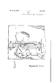
March 29, 1932. 1,851,182
OVEN
Original FiledrOct. 8, 1.926 5 Sheets-Sheet l March 29, 1932.
T. A. HILL OVEN Original Filed Oct. 8 1925 5 Sheets-Sheet March 29, 1932. l 1,851,182
OVEN
Original Filed Oct. 8, 1926 5 Sheets-Sheet 3 gvwemtoz "r. A. HILL March 29, 1932.
OVEN
5 Sheets-Sheet 4 Original Filed Oct. 8, 1926 T. A. HILL 1,851,182
OVEN
5 Sheets-Sheet 5 March 29; 1932..
gvwemtoz Original Filed Oct. 8, 1926 1 (MM b.
l 'atente Mar. 29, i932 UNITED STATES PATENT OFFICE THOMAS A. HILL, OF NEW YORK, N. Y., ASSIGNOR TO GRIFFITHA E. HILL, OF
7 NEW YORK, N. Y.
OVEN
Application filed October 8, 1926, Serial No. 140,270. Renewed January 6, 1932.
My invention relates to improvements in ovens and more particularly has reference to and is illustrated in the accompanying drawings in its application to an automatic culinary oven, such as may be used in gas, 011,
coal or electrical ranges or stoves. The socalled automatic character of the oven consists in means for regulating or adjusting the oven-shelf or bottom from the outside of the "I oven, so as to avoid the necessity of stooping or bending and peering and reaching into the oven to get at the cooking, thereby frequently burning the hands, arms, and kitchen'linen, especially in withdrawing the cooking for attention, and returning same into the oven. Frequently a roast or broil is dropped on the floor. when changing same in the oven, thus not only spoiling the cooking, but also soiling the floor, and when the broil has taken fire, as frequently occurs, the necessity of handling same at close handv subjects the handler to the great danger of inhaling the flame, which is certain and painful death, as well as the danger of spreading fire throughout the house.
Various attempts have been made to over- I come more or less ofthese dangers and annoyances, but these efforts have not heretofore been successful largely because of failure 30 to appreciate the correct nature and ramificationsof the problems involved. For instance, an adjustable oven shelf should be projectable as well as elevatable, otherwise the same annoyances and dangers remain toa largeextent, and in providing for both'movements, the oven must remain unobstructed at all times, otherwise this loss of service will defeat the utility of the oven. Furthermore, it must be easy to operate and foolproof, requiring practically no attention. The mechanism should be covered to avoid possible accidents, and the mechanism of one oven should not interfere with the mechanism of any other oven in the same range or stove. should be adaptable to present standard types of stoves or ranges Without making radical and extensive changes therein. operative frbm the outside and not interfere inside with the oven bottom, side walls or The mechanism It should be top, nor materially reduce the capacity of the oven. The shelf when adjusted should remain so at points of elevation, and should automaticallylock to prevent accidents in case the handle therefor is accidentally or prematurely released, and the handle should occupy an out-of-the-way position to which it should always automatically return when not in actual use. A multiplicity of hand levers should be avoided to prevent confusion, and a single universal hand control of simple and easy operation always ready and within convenient reach from the front of the oven should be provided, the movement of the hand lever should be logical with respect to the movement of the shelf for obvious reasons. The elevation of the shelf must be of substantial amount to permit use of the bottom of the oven and the shelf at the same time, and the projection of the shelf or bottom must be for substantially the entire depth of the same to provide fullest accessibility to the contents thereof. The oven should be properly lined as usual, and the shelf should be open for the circulation of heat, and should at all times be rigidly secured at all four corners to insure against tilting, canting, or wabbling. For purposes of universal adaptation, the oven shelf should be convertible as a broiler and pan holder for use also in a broiling oven where the pan beingconsiderably below the broiling flame will not scorch, burn, or become, incrustated, and the mechanism should be adaptable to ovens of different sizes with the least possible changes.
Without attempting to be exhaustive, these few requisites will suflice to point out some of theessential attributes of a properly constructed-automaticoven. In no previously known attempt have'half these requirements been fulfilled, but it is believed thatapplicants preferred embodiment of invention as illustrated in the accompanying drawings fairly meets all of these requirements, and more, the 7 same being more fully referred to as follows:
Fig. 1 is a perspective view, parts being broken away, illustrating a suitable form of elevating and projecting mechanism, embodying an application of my invention. Fig.2 is a perspective view, partly-broken away, illustrating a suitable form of slide mo bearing shown in Fig. 1. Fig. 3 illustrates in perspective, parts being broken away, a preferred form of elevatin mechanism adapted for use at one side of the oven. Fig. 4 illustrates in vertical cross-section a suitable form of clutch mechanism and control handle.
Fig. 5'is a side view ofthe lower part thereof, looking from right to left. Fig. 6 is a perspective view of the upper part of the clutch fork shown in Fig. 4. Fig. 7 illustrates in perspective part of the clutch mechanism shown in Fig. 4. Fig. 8 is a view looking from right to left thereat. Fig. 9 is a detail, partly in cross section, of the handle mechanism. Fig. 10 is a perspective view, parts being broken away, illustrating a modified form of shelf for lifting and sliding movement. Fig. 11 is a diagrammatic view of electrical connections for operating the shelf electrically. Fig. 12 is a perspective view, parts being broken away, and parts omitted, illustrating an arrangement for electrically projecting and elevating the shelf. Fig. 13 is a perspective view of gas valve locking arrangement. Fig. 14 is a perspective view illustrating a broiler and support therefor in combination with an adjustable oven shelf, and Fig. 15'is a diagrammatical view of the preferred lifting chain connection.
15 and 16 indicate plates preferably of steel, and preferably of about one-sixteenth to one-eighth inch thickness which serve as the side lining of the oven, being preferably suitably secured at the top and bottom thereof in any suitable manner. These plates preferably serve as supporting means for the elevating and projecting mechanism, and also as a guide for the movement of the same. 17 indicates a shaft preferably behind the front frame of the oven and below the bottom thereof forward of the burner, in connection with which the elevating and sliding mechanism is preferably driven, and 18 indicates a vertical shaft at the back and at one side within the corner of the oven in connection with which the projecting mechanism is operated. This shaft 18 is preferably flat sided with round ends, the top and bottom being provided with suitable bearings such as 19, as shown. The ends of the drive shaft 17 are referably supported upon opposite walls 0 the oven and may also pass through and be additionally supported by the hanger plate or lining 16, and upon this shaft 17 are suitably mounted sleeves or tubes, which together with the shaft, control the movement of certain operating levers, as hereinafter described.
The elevating and projecting mechanism for the shelf is for the most part duplicated preferably behind the lining and at each side of the oven, and for this reason, and to simplify the description, it will only be necessary in most instances to refer to one complete side mechanism such as illustrated. 20.
20", and 21, 21', indicate channel pieces mounted links 22, 22, which in turn are piv- L otally connected to the ends of the arms 23, 23 of the pinions 24, 24, which in turn mesh with the rack 25, slidable in bearings 26, 27, secured to the plate 16. This rack is in turn pivotally connected to the link 28, the other end of which is pivotally connected to the link 29, the other end of which is pivotally mounted in the plate 16, as shown. At the pivotal connection between the links 28 and 29, is pivotally secured a link 30, the other end of which is pivotally connected to the link 31 which is secured upon the shaft 17 so that upon rotating said shaft the links 28 and 29 are brought into alignment or pushed backwardly, as shown in the drawings, thereby raising or lowering the rack 25, which in turn rotates the pinions 24, 24 oppositely, and the arms of these pinions being pivotally connected by links to the channel guides 20, 21', raise and lower the same equally and simultaneously'.
Upon the channel guides 20 to 21" are secured base channels 32, 32, and above the same are secured other channels 33, 33. In the lower channels 32, 32 are slidably mounted the angles 34, 34 upon which are mounted and equally spaced four sets of wheels or washers 35 and pinions 36 free to rotate thereon. The upwardly projecting edge of the channel 32 is toothed as indicated at 37 to provide a rack for engaging the pinions 36, and the oppositely projecting edge of an upper channel 38 is also provided with teeth 39, also for engaging pinions 36. Upon the inner faces or sides of the upper toothed channels 38 are secured strips 40, 40, which serve as the sides of the shelf or frame which is preferably grid-like or open-work, to allow the heat to pass therethrough, and the front portion is preferably dropped down forming an apron 41, as shown, so that when the shelf is all the way down in the oven and projected entirely within the oven, the apron 41 meets .the top of the front frame at the bottom of the oven, forming a step or ledge above the bottom of the oven, the upper part of which continues back into the oven serving as a superposed oven bottom until the same has been lifted to serve as a shelf. From this it will be seen that when the oven shelf is down, the entire space within the oven is preserved and there is nothing to indicate that it is different from the ordinary oven. no mechanism being exposed. As the shelf is raised, the only moving part observable is the inwardly projecting edges of the guides 20 to 21 inclusive which travel upwardly along the front and back edges ofthe hanger plates or lining 15, 16, which are separated from the front and back of the oven by a 7 axis 17.
pins 89 enter the holes 90 slightly" in ad-;
rotate upon the housing 63. For convenience of illustration, the upper broken section of Fig. 4 is drawn at right angles to the position it would occupy with reference to the lower broken section of Fig. 4, so that when the handle 91 is thrown leftwardly, it is in fact drawn toward the operator or toward the front of the oven. When this is done, said handle being pivotally secured at 92, upon the shaftor rod 81, it depresses the cup-like end 93 of the inner tube 7 8 against the action of the spring 94, the lower end of which engages the cup-like portion 93 at 95, as shown, and the upper end of which'penetrates the shaft 81 at 96, thus tending to keep the inner tube 7 8 projected upwardly against the-handle 91, but when said handle is pulled to or pushed away from the operator, its flanged base 97 overcomes the action of the spring 94 by distending the same and forcing the inner sleeve 7 8 downwardly, thereby pushing down the clutch member 7 7 and disengaging the tooth 7 9 thereof from the pinion 69, at the same time the fork 78 of said clutch member in moving down releases the cone 86, which under influence of the spring 87 allows the toothed disc 88 to engage the pinion 69, thereby locking said pinion against rotation and holding the oven shelf in its elevated position, from which it will be seenthat the oven shelf is normally locked fromverticalmovement at all times, but by pulling or pushing upon the handle 91, the lock is disengaged, and slightly before entirely being disengaged, the pinion 69 is engaged, thereby providing for vertical adjustment of the shelf as the handle and lever mechanism is rotated about the When the handle 91 is released, the
vance of the release of the tooth 79 from the pinion 69.
The outer tube 65, 65' of the handle mechanism is provided with a handle 98, which normally extends laterally behind the lever mechanism. When it is desired to project the even shelf or the oven bottomout of the oven, this handle 98 is gripped and pulled from the back to the right or left side around the lever mechanism. In doing so the handle 98 ro tates the upper part 65 of the outer tube, which is provided upon the inside with a spiral groove 99 of considerable pitch and is engaged by the end of the pin 100, secured in the rod 81, and free to move in the slot 101 of the inner tube 78, thus the rotation of the upper end 65 of the outer tube by the handle 98 depresses the same against the lower end 65' of the outer tube. which thereby depresses the clutch member 72, causing the tooth 74 to engage the pinion 70. By rotating the handle 98 oppositely, the lower tooth 75 of the clutch member 72. is lifted into engagement with the pinion 71, and when the handle 98 stands normally rearward as explained, the pinions and 71 are free of the clutch, al-
lowing the handle to turn freely upon its bearing 17. In order to keep theclutch clear of the pinions when the handle is released, the outer tube is formed in two sections 65, 65, to the lower of which is secured a sleeve 102, by a pin 103, or other suitable means, the inside of the upper end of the sleeve being threaded as indicated at 104, and the lower end of the upper tube 65 being threaded to engage therewith. This allows the upper section 65 to turn freely with respect to .the lower section 65 on fine threads of low pitch, thus not appreciably separating the sections when relatively turned, but allowing the longitudinal movement of one section to communicate said movement to the other. Two springs are wound oppositely around the base of the upper section 65, one end of each spring engaging the tube 65, and the other end of each spring engaging the sleeve 102 as shown, thus tending to keep the upper tube 65 from rotating in either direction, the pin 100 being at about the centre of the, high pitched spiral groove, so that in turning the handle 98, one of the springs 105, 106, is Wound tighter, while the other is slightly unwound, this unbalanced condition returning the handle 98 to normal position when released. 1
In the pi -ferred modification of lifting mechanism shown in Fig. 3, segmental pinions 107, 108, are pivoted at 109, 110, respectively to the hanger plate or lining 15, the pinion 107 meshing with the rack 111, with weighted end 111, and the pinion 108 meshing with the rack 112, both of said racks being formed with or secured to the slidable base 113, and the rack 111 being cut-away to allow for the passage of the pinion 108 through the same. Another segmental pinion 114 may also be mounted upon the same stud 109, or
lower down if desired, for also engaging the rack 111, and to said pinion 114 is pivotally connected a link 115 which is pivotally conlinks 118 extend down opposite sides thereof to keep the chain centralized-on said periphery, the 'end of the chain being anchored by a pin 121. These chains at their lower end are pivotally connected to-the guide channels 20 to 21, so that by operation of the, shaft 17, the segmental gear 114 raises or lowers the rack 111, which in turn causes the segmental gears 107, 108, to rotate oppositely, raising and lowering the shelf equally and at all four corners, the link or lever 116 shown in Fig. 3 would be mounted in the same manner as link or lever 31 shown in Fig. 1.
Referring now more particularly to Figs. 10 to 12 inclusive, and especially the latter, I have shown a suitable arrangement for an electrically operated mechanism for adjustslight space of about one-eighth of an inch. For projecting the shelf, the post 18 in the back corner of the. oven is rotated. This st is provided with a vertically slidable earing 42, having an arm 43, pivotally connected at the opposite end to the end of the arm 44, the other endof which is pivotally connected to the cross bar 45, the ends of which are securedto the channels 34, 34, and as these channels are pushed outwardly by the rotation of the post 18, the pinions 36 riding upon the elevatable, but non-projectable, rack 37, engage the upper rack 39, cause it to travel out of the oven twice as fast and twice as far as the supporting angles 34, 34, so that when the shelf 40, 40 is projected its maximum distance out of the oven, the angles 34, 34 are still partly within the oven, but support the projected shelf half of its projected length, telescopically sliding therewith back into the oven when the rotation of the post 18 is reversed. Beneath the back of the shelf may of course be provided a suitable slot or horizontal support for carrying the weight of the levers 43, 44, and to insure the riding vertically of the bearing 42 upon the post 18, the same being of any well known suitable form.
For projecting the bottom of the oven, the lever 45 is secured upon the sleeve 46, rotatable upon the shaft 17, said lever 45 being pivotally connected to the lever 47, the opposite end of which is pivotally connect-ed to the slide bar 48, adapted to slide in the channel 49 of the bearing 50, shown to advantage in Fig. 2, and secured to the hanger plate 16, and to one end of the slide bar 48 is also I pivotally connected the lever 51, which in turn is pivotally connected to the lever 52, having a ring 53 at one end and a filler 54 of circular exterior form and rectangular interior form to engage the bar 18, said lever 52 being thus operatively connected to the lever 45, thereby projecting the bottom of the oven.
Also, upon the shaft 17 is another sleeve 55, which carries lever 56, the other end of which pivotally connects to the lever 57, piv 'otally-connected at its opposite end to the slide bar 58, which is pivotally connected at its opposite end to the lever 59, the opposite end of which is pivotally connected to the lever 60, the opposite end of which has a square hole 61 to engage the post 18. A similar lever 43 above'mentioned, extends inwardly from the post 18 to engage another lever similar to the lever 44, to project the shelf. \Vhen the shelf is elevated with food cooking thereon in the oven, the bottom may be brought out of the oven to arrange cooking thereon inde endently of the elevated shelf.
teferring now more particularly to Figs. 4 to 9 inclusive, the clutch mechanism and handle control therefor is illustrated in a suitable form, more particular reference being had to Fig. 4, wherein 62 indicates the ing is provided with an annular groove for about one-third of its circumference to allow for the passage of the handle tube 65 which rotates about the centre shaft 17. A
At the centre of the head 83 of the housing 63, a flat sided hearing or shank 84 is provided to slidably support the fiat sided stud such as hexagon 85, upon the inner end of which is a cone-like structure 86, hollowed outbeneath to receive the coiled spring 87, which normally projects the same from the inside of the housing leftwardly as shown, and upon the inner face of the cone member 86 is secured a disc 88, having an annular series of studs 89, adapted to register withholes 90, in the pinion 69, secured to the shaft 17.
The handle or control lever normal-1y stands substantially upright at the front and at one ment of shelfand bottom, such as may be desirable for electrically operated ranges, or otherwise. Beneath the bottom of the oven is suitably mounted an electric motor 122, upon the ends of the shaft of which and in alignment therewith, are secured rectangular sockets 123, 123', into the ends of which may slide rectangular pins 124, 124', preferably of non-magnetic material, the other ends of which are secured'to a round softiron core, longitudinally slidable within the magnets 125, 126, 125', 126', and at the other end of said magnet cores is secured extensions 127, 127', upon the ends of which are mounted beveled 'pinions 128, 128, and opposite beveled pinions 129, 129', the ends of the shaft being suitably mounted and provided with opposite compression springs 130, 130'. The magnet cores referred to being of a length equal to the length of two of the magnets, such as 125, 126, will be pulled in the direction of the particular magnet of the two which may be energized. For instance, assuming" that the magnet 126 is energized, the pinion 129 will engage with the beveled pinion 131, the square end 124 sliding within the square socket123. If the magnet 125 is energized, the core will centralize therewith by moving leftwardly, causing pinion 128 to mesh withv the pinion 131, and the motor running in the meantime will rotate the vertical shaft 132 gized, and for which purpose suitable operating buttons, shown in Fig. 11, may be pressed.
The shaft 132 is provided at the lower end 2 with a reduced portion 134, leaving a shoulder which rests upon the bracket 135 for sup port, and 136 is a.;housing which engages the shaft 132, and upon which is secured a beyeled pinion 137, which is retained by said housing in engagement with a pinion 138 upon one face of the pinion 13 9, the latter being thereby rotated and meshing with the pinion 140, upon the shaft 141, rotates the latter. The forward end of the shaft 141 is provided-with a spiral 142 and is mounted at the end in the frame 143, said frame slidably engaging the hanger plate '15, so as to be guided up anddown the same. 144 indicates the shelf or bottom supporting surface beneath and to which is secured the bearing 145 internally threade'dto engage the screw or spiral 142, so that as the latter rotates, the
shelf travels out'or into the oven. From the bearing 145 projects the pin 146 whichengages a slot 147 in a supporting bar 148, said slot 147 being of a length equal to about half the total projection of the shelf, so that as the shelf moves outwardly, the pin engages the end of the slot 147, pulling the supporting bar 148 half way out to support the shelf and likewise in returning the pin 146 strikes the opposite end of the slot 147 and moves the supporting bar 148 in with the shelf, said supporting bar having a flared end 149, engaging the side 143 of the elevating frame. The same arrangement being duplicated at the opposite side provides the necessary support at both sides of the ovenfor the slide mechanism. 4
The worm 133 is provided. for lifting the shelf and is reduced at the lower end as in dicated at 134, the bracket 135 serving to support said worm. The frame 143 is provided at that corner with a heavy bearing 150, threaded to engage said worm, said worm and bearing being sufiiciently heavy and said bearing being sufliciently extended to pro:
vide ample strength for carrying the entire Fig. 11, wherein a suitable source of poweris indicated by reference character .151, one side of which is connectedto the electric motor 122, and the other side of which passes to the button 152, which when pressed closes the circuit, allowing the current to pass through coil 125 and back to the motor, thus projecting the shelf. When the'opposite projection of theshelf is required, thebutton 153 is pressed, allowing the current-to pass from the source of supply thereto and back to the motor to coil 126. When vertical adjustment of the shelf is required, the'button 154 may-be depressed, allowing the current from the source of supply to pass therefrom through the magnet 125 to the motor, and when the opposite vertical movement of the shelf is required, the button 155 is depressed, allowing the current to pass therethrough and through the coil 126', to the motor, these buttons being preferably located at one side of the oven close to the front thereof. For convenience of illustration neither the electric diagram nor the mechanical transmission in connection therewith has been duplicated for the shelf, shown to advantage in Fig. 10, is also preferably provided with heavy ribs such as 156, 157, and 158 radiating from the heavy bearing or housing 150 to provide the necessary support, and in addition to these ribs, extra ribs such as 159 may besuitably provided inthe casing for insuring proper 14, it will be observed that the upper surface of the shelf, preferably in grill or grid form, may be made in several sections, so that the back and front portions 160, 161, may be pivotally connected with the shelf portion 162 as shown, so as to be thrown upwardly at right angles thereto, suitable stops 163 preventing the same from moving beyond the vertical position. This permits a pan, such as a roasting pan, to rest upon the shelf 162 between the upturned ends thereof, and a broiler 164: to be pivotally mounted in the tops of the upturned portions, said broiler having an axial portion 165 with a pair of discs 166 at one end thereof to rest either side of the back projecting portion 161, the front end of the shaft 165 having a flat portion 167 adapted to be seated in the rectangular opening 168, so that by pressing upon one side of the broiler 165 the same will turn in the bearings 168, 169, and due to the fiat form of the extensions 167 resting in the flat bearing 168, will normally remain horizontal. The upper and lower portions of the broiler may be hinged at 170 in the usual manner and may be suitably fastened at 171 in any convenient manner, from all of which it Will'be-seen that when steaks. or slices of bread have been secured in the broiler they may be raised or lowered to the flame, and may be Withdrawn from the oven for examination or turning, any drip therefrom being caught in the pan below, instead of placing the broiler in the pan and lifting the pan to the flame as usual, where it becomes incrustated and burnt, the gravy therein sometimes taking fire.
Referring to Fig. 15, the lifting chains at each side of the oven are preferably double and continuous, that is to say, the free ends of each chain are secured to the top 'and bottom' of a guide such as 20 or 21, engaging a segmental pinion 107 and passing over idler sprockets 179, 180, 181, or, engaging segmental pinion 108 and passing over idler sprockets 182, 180, and 181, the idlers 180 and 181 being doubled upon the same pins so as to carry both chains 117 and 117 Of course it will be understood that various modifications'may be made in the construction and arrangement of parts without departing from the spirit of the invention as claimed.
I claim 1. In a device of the class described, means for raising and lowering part of an oven, and in combination therewith means for independently shifting the same laterally, both of 1said means operable from the same contro 2. In combination with the oven of a stove, a hand lever, means in combination therewith for raising and lowering the shelf of said oven while said shelf is entirely in or out of said oven, and also for projecting said shelf at any point of elevation.
3. An oven of the class described having a shelf and unitary operating means for adjusting said shelf in either of two planes irrespective of the position of said shelf.
4. In combination with an oven having an adjustable shelf and means for raising same,
means for ro'ecting said shelf from said.
oven, part 0 said raising means being part of said pro ecting means.
5. In combination with an oven having an adjustable shelf and means for raising same,
means for projecting said shelf from said oven, all of said means substantially clear of v the opening to said oven, and operative by a single instrumentality.
6. In combination with an oven, a lever ivo-ted at one side thereof, a movable s elf therein, elevating and projecting mechanism within and at opposite sides of said oven, and means for connecting same to said lever so that upon the operation of said lever either said elevating or projecting mechanismwill move said shelf.
7. An oven having a movable shelf and mechanism to move the same, said mechanism positively connected throughout, and adapted to move said shelf in either of two directions at an angle to each other, and a single lever outside said oven to control said movements.
8. An oven of the class described having a shelf, mechanism for moving said shelf vertically or horizontally, and selective operating means for actuating either of said mechmovable shelf, mechanism for moving said shelf, hand controlling means therefor outside said oven, means for engaging and disengaging said controlling means and said mechanism, said controlling means adapted to always maintain the same predetermined position when not in use.
10. An oven of the class described having a shelf, mechanisms for moving said shelf vertically or horizontally, a single drive shaft therefor, and means for operating said drive shaft.
11. In an oven of the class described, an adjustable shelf, means for raising and lowering the same, said means adapted to project the same from and into said oven, said raising means supporting part of said projecting \means. a
12. In a device of the class described, means for raising and lowering part of an oven, and in combination therewith means for shifting same laterally, both of said means operable from the same control, said lateral shift ing means including a combination of slide bars operatively connected together.
13. In combination with an oven, a lever pivoted at one side thereof, a movable shelf therein, elevating and projecting mechanism within and at opposite sides of said oven,
and means for connecting same to said lever so that upon the operation of said lever either said elevating or projecting mechanism will move said shelf, said operation including a twist of said lever.
14. In combination with an oven, an adjusting shelf, therefor, a handle upon the outside of'said oven, supports for said shelf,
mechanism for adjusting the same in two positions at right angles to each other, said supports and mechanism substantially within the walls of said oven, and means for con necting and disconnecting said handle with said mechanism for the Vertical or longitudinal adjustment of said shelf.
15. A lever and clutch mechanism for raising and lowering, and for sliding part of an oven, and means in combination therewith for operating one or the other each time said lever is twisted in one direction and operated while in said direction.
16. In combination with an oven, shelf raising and projecting mechanism, and outside handle therefor, and a clutch adapted to connect said handle and mechanism. v
17 An oven of the class described having a movable shelf, mechanism for moving said shelf, hand controlling means therefor outside said oven, clutchmeans for engaging and disengaging said controlling means and said mechanism.
18. An oven of the class described having a shelf and mechanism for moving the same, an outside handle for operating said mechanism, and a clutch between said handle and mechamsm.
19. An oven of the class described having a movable shelf, mechanism for moving said shelf, hand controlling means and a clutch therefor outside said oven, said mechanism outside the useful zone of said oven.
20. An oven of the class described with an opening thereto and an adjustable shelf therein, mechanism for moving said shelf, means for operating said mechanism, and clutch meansfor connecting and disconnecting said operating mechanism.
21. An oven of the classdescribed having a shelf and mechanism for moving the same, an outside handle for operating said mechanism, and a clutch between said handle and the outside of said oven. 22. An oven of the class described with an mechanism, said clutch having a housing at vertically and horizontally, and clutch means for detachably and operatively connecting said shelf and mechanism. v
23. In a device of the class described, means for raising and lowering part of an oven, and in combination therewith, means for shifting same laterally, both of said means operable from the same control, and a clutch in combination with said control for engaging and disengaging either of said means.
'24:. In an oven of the class described, an adjustable shelf, a support for said shelf, means for raising and lowering and for projecting said support including a handle outside of said oven, and a clutch operative by said handle for connecting either said raising and lowering or said projecting means.
25. An oven of the class described having a shelf and mechanism for moving the same, an outside handle for operating said 'mechanism, said mechanism including a single shaft transversely of said oven for driving said.
mechanism, said handle loosely mounted upon the outside end. of said shaft, and a clutch operative by said handle to engage the same with said mechanism.
26. In combination with an oven having an adjustable shelf and means for raising same,
means for projecting said shelf from said oven, all of said means substantially clear of the opening to said oven, and operative by a single instrumentality, said instrumentality including clutch mechanism adapted to connect either said raising or projecting means therewith. j
27 A lever and clutch mechanism for raising and lowering, and for sliding part of an oven, and means in combination therewith for operating one or the other each time said lever is twisted in one direction and operated while in said direction, said means comprising a sliding clutch and means in com bination with said lever for operating the same. 28. In an oven of the class described, an adustable shelf, a support for said shelf, means for raising and lowering and for projecting ver is twisted in one direction and operated While in said direction, said means comprising a sliding clutch, and means in combinationwith said lever for operating the same.
30. An oven of the class described having a shelf and mechanism for moving the same, a single drive shaft therefor across the front and below the bottom of said oven having an upright handle at one end. I
31. In combination with an oven, shelf adjusting mechanism, an outside handle therefor, and means for automatically returning said handle to normal position immediately the same has been released.
32. An oven of the class described having a shelf and mechanism for moving the same, an outside handle for operating said mecha nism, and a counter-weight for returning said 10 handle to normal position when not being used.
33. An oven of the class described having a shelf and mechanism for moving the same, an outside handle for operating said mechanism, said handle adapted to automatically return to an out-of-the-way position when released by the hand.
34. In an oven of the class described, an adjustable shelf, a support for said shelf, means for raising and lowering and for projecting said support including a handle outside of said oven. and automatic means for returning said handle when released to its normal position.
35. In an oven of the class described, an adj ustable shelf, a support for said shelf, means for raising and lowering and for projecting said support including a handle outside of said oven, and automatic means for returning said handle when released to its normal position.
36. An adjustable oven shelf control adapted when released to automatically lock the shelf in its adjusted position and return to its normal position.
37. An oven of the class described having a shelf and mechanism for vertically moving the same, an outside handle for operating said mechanism, and means for automatically lockingsaid shelf in its moved position when said handle is released. t
38. An oven of the class described having a shelf and mechanism for moving the same, an outside handle for operating said mechanism, and means for automatically locking said shelf in its moved position and returning said handleout of the way when same is released.
39. In an oven, a shelf, a plurality of pair of operatively connected arms forming supports for said shelf, a rod pivotally connected to an arm of each pair and movable toad just said shelf, means for rotating said rod to adjust said shelf, and locking means for holding said rod against rotation to secure the shelf in adjusted position.
40. A combination oven-shelf and broiler support, said support providing clearance for the turning of the broiler.
C3 41. An oven shelf with collapsible broiler supports, and means for supporting a pan therebetween, said support adapted to be held upright at the front and back when in use.
42. An adjustable combination oven shelf and collapsible broiler support, said shelf adapted to receive said collapsed support within the face of said shelf.
43. A combination oven-shelf and broiler support, said support providing clearance for the turning of the broiler and having a bearing adapted to hold the broiler in fixed position.
44. In combination with an oven having an adjustable shelf and means for raising same, means for projecting said shelf from said oven, said shelf having collapsible means for holding a broiler in operative position.
45. A device of the character described embodying a shelf having supporting means, a carrier on which said shelf is mounted for projecting movement, means for raising and lowering said carrier, means for projecting said shelf on. said carrier, in combination with a drip pan adapted to be supported by said shelf, and agrid adapted to be supported by said supporting means, said pan adapted to underlie said grid, movable therewith, and juxtaposed thereto.
46. In combination with an oven, an adjustable shelf therefor, a handle upon the outside of said oven, supports for said shelf, and mechanism for adjusting the same in two positions at right angles to each other, said supports and mechanism substantially with in the walls of said oven, and hinged sections adapted to lie substantially flat with respect to said shelf and to be elevated at right angles thereto serving as a support fora broiler.
47. A device of the character described embodying a shelf having supporting means, a carrier on which said shelf is mounted for projecting movement, means for raising and lowering said carrier, means for projecting said shelf on said carrier, in combination with a drip pan adapted to be supported by said shel-fand a grid adapted to be supported by said supporting means, said pan adapted to underlie said grid, movable therewith, and juxtaposed thereto irrespective of the position of said carrier.
48. In combination with an oven, an adjustable shelf therefor, a handle upon the outside of said oven, supports for said shelf, and mechanism for adjusting the same in two positions at right angles to each other, said supports and mechanism substantially within the walls of said oven, and hinged sections adapted to lie substantially flat with respect to said shelf and to be elevated at rlght angles .thereto serving as a support for a broiler, and means in combination therewith for preventing the turning of said broiler therein without first disengaging the same therefrom.
49. In combination with an oven, an adjus'table shelf therefor, a handle upon the outside of said oven, supports for said shelf,
andmechanism for adjusting the same in two positions at right angles to each other, said sup rts and mechanism substantially within t e walls of said oven, and hinged sections adapted to lie substantially flat with respect to said shelf and to'be elevated at right angles thereto serving as a support for a broiler, said broiler support serving with said shelf as part of the same" when folded flatly there'- 50. In combination with an oven, an adjustable shelf therefor, a handle upon the outside of said oven, supports for said shelf,
and mechanism for adjusting the same in two positions at right angles to each other, said supports and mechanism substantially within the walls. of said oven, and hinged sections adapted to lie substantially flat with respect to said shelf and to. be elevated at right angles thereto serving as a support for a roiler.
51. In combination with an oven, a movable part thereof provided with a supporting rack, an under rack and a pinion thereon meshingtherewith and also meshing with said first mentioned rack, and means for moving said pinions so as to cause said movable parts to'travel in and out of'said oven.
52. An oven having an adjustable shelf, guides at opposite sides thereof, toothed segments having arms pivotally secured to said guides and meshing with relation to each other, links connecting the free ends of said armsto said shelf, and operating means connecting with one of said'arms whereby said sides thereof, said mechanism at each side including a vertically reciprocating rack, pinions meshing at opposite sides thereof,
' arms from said pinions extending crosswise to pointsadjacent the ends of said shelf, and connections from said shelf to said arms.
55. A chamber having a movable shelf, mechanism for moving said shelf at both sides thereof, said mechanism at eachside including a vertically reciprocating rack, pinions meshing at opposite sides thereof, arms from said pinions extending crosswise to points adjacent the ends of 'saidshelf, links connecting said arms to said shelf.
56; A projecting mechanism of the class described comprising a base rack, an intergaging said rack, a superposed slidable rack also engaging said pinions, means for projeeting said intermediate and superposed members, and in combination means forelevating and depressing said mechanism.
57 In-combination with an oven, a mov-- able part thereof provided with a supporting rack, an under rack and a pinion thereon meshing therewith and also meshing with said first mentioned rack, and means for mova support therefor and means for moving said support.
' 58. An oven of the class described with an mediate slidable member having pinions enmeans for engaging said segments, links con nected at the other ends of said levers and to said shelf, link connection to said means,
' a drive shaft and lever secured thereto and also connected to said last mentioned link connection, and means for operating said mechanism for moving said shelf at both sides thereof, said mechanism at each side including a vertically reciprocating rack, pinions meshing at opposite sides thereof, arms from said pinions extending crosswise to points adjacent the ends of said shelf, links connecting said arms to said shelf, a pair of links pivoted together at adjacent ends, the free end of one link pivoted to said rack, the free end of the other link pivoted to-a stationary part of said chamber, and means for moving the adjoining ends of said links transversely.
60. An oven of the class described having a shelf and unitary operating means for adjusting said shelf in either of two planes.
61. In a device of the class described, means for raising and lowering part of an oven, and in combination therewithmeans for shifting laterally, both of said means operable from the same control, said lateral shifting means including a combination of slide bars geared together.
62.111 a device of the class described, means for raising and lowering part of an oven, and in combination therewith means for shifting laterally, both of said means operable from the same control, and a clutch in combination with said control for engaging and disengaging either of said means.
63. An elevating and depressing mechanism comprising vertically sliding side members, a shaft transversely thereof and lever connections between said shaft and said side members, said lever connections being adapted to move said-members vertically or laterally.
64. An oven of the class described having a movable shelf and bottom, 'mechanism therefor, an outside control for moving same, a single shaft for driving said mechanism, a selective transmission connectable thereto,
an outside handle and means in combination therewith for connecting same to said selective mechanism. j
65. An elevating and depressing mecha- 5 nism comprising vertically sliding side members, a shaft transversely thereof and lever connections between said shaft and said side members, said lever connections being adapted to operate said mechanism when said shaft 1 is rotated, and in combination therewith a projecting mechanism, and a lever for operating both of said mechanisms.
66. An oven of the class described having a movable shelf and bottom, mechanism therefor, an outside control for moving same,
a single shaft for driving said mechanism, a
selective transmission connectable thereto, an
outside handle and means in combination therewith for connecting same to said selective mechanism, said means operative from the grip of said control.
67. An adjustable oven shelf control adapted when released to automatically lock the shelf in its adjusted position and return to its normal position. i
68. An oven of the class described having a shelf and mechanism for vertically moving the same, an outside handle for operating said mechanism, and means for automatically lockin said shelf in its moved position when sai handle is released.
69. An oven ofthe class described having a shelf and mechanism for moving the same, an outside handle for operating said mechanism, and means for automatically locking said shelf in its moved position and returning said handle out of the way when same is released.
70. In an oven, a shelf, a plurality of pairs- I 40 of operatively connected arms forming supports for said shelf, a rod pivotally connected to an arm of each pair and movable to adjust said shelf, means for rotating said rod to adjust said shelf, and locking means for holding said rod against rotation to secure the shelf in adjusted position.
In testimony whereof I hereunto aflix my signature. 5o THOMAS A. HILL.
Priority Applications (1)
| Application Number | Priority Date | Filing Date | Title |
|---|---|---|---|
| US140270A US1851182A (en) | 1926-10-08 | 1926-10-08 | Oven |
Applications Claiming Priority (1)
| Application Number | Priority Date | Filing Date | Title |
|---|---|---|---|
| US140270A US1851182A (en) | 1926-10-08 | 1926-10-08 | Oven |
Publications (1)
| Publication Number | Publication Date |
|---|---|
| US1851182A true US1851182A (en) | 1932-03-29 |
Family
ID=22490497
Family Applications (1)
| Application Number | Title | Priority Date | Filing Date |
|---|---|---|---|
| US140270A Expired - Lifetime US1851182A (en) | 1926-10-08 | 1926-10-08 | Oven |
Country Status (1)
| Country | Link |
|---|---|
| US (1) | US1851182A (en) |
Cited By (2)
| Publication number | Priority date | Publication date | Assignee | Title |
|---|---|---|---|---|
| US3059634A (en) * | 1960-01-20 | 1962-10-23 | Susan B Brinkman | Power operated oven rack |
| US20140239788A1 (en) * | 2013-02-22 | 2014-08-28 | General Electric Company | Appliance and a rack assembly for the same |
-
1926
- 1926-10-08 US US140270A patent/US1851182A/en not_active Expired - Lifetime
Cited By (3)
| Publication number | Priority date | Publication date | Assignee | Title |
|---|---|---|---|---|
| US3059634A (en) * | 1960-01-20 | 1962-10-23 | Susan B Brinkman | Power operated oven rack |
| US20140239788A1 (en) * | 2013-02-22 | 2014-08-28 | General Electric Company | Appliance and a rack assembly for the same |
| US8936333B2 (en) * | 2013-02-22 | 2015-01-20 | General Electric Company | Appliance and a rack assembly for the same |
Similar Documents
| Publication | Publication Date | Title |
|---|---|---|
| US11925293B2 (en) | Stove with a height-adjustable grill grate | |
| US2812706A (en) | Electrical broiler | |
| US3059634A (en) | Power operated oven rack | |
| US2114697A (en) | Broiler | |
| US1851182A (en) | Oven | |
| US2127146A (en) | Adjustable broiler for ranges | |
| US1974830A (en) | Rack or slide for cooking stoves or the like | |
| US2027124A (en) | Broiler for gas ranges | |
| US1998343A (en) | Cooking range and stove | |
| US2919691A (en) | Mechanism for adjusting the height of racks in range ovens | |
| US2331707A (en) | Top and bottom fired broiler | |
| KR101479422B1 (en) | Charcoal roaster | |
| US2218961A (en) | Gas range construction | |
| KR102169100B1 (en) | Grilled table | |
| US2633840A (en) | Auxiliary oven | |
| US2133835A (en) | Stove | |
| US3011850A (en) | Power operating adjustable broiler for cooking ranges | |
| US1533256A (en) | Adjustable shelf for ovens | |
| US2054327A (en) | Cooking stove or range | |
| US2355230A (en) | Broiler unit | |
| US2047979A (en) | Drawer type broiler | |
| US2204381A (en) | Broiler construction | |
| US2480250A (en) | Shelf elevating device for cooking or broiling ovens | |
| US1586738A (en) | Cooking apparatus | |
| US2130168A (en) | Oven construction |