US1850737A - Ventilating-louver for windows - Google Patents
Ventilating-louver for windows Download PDFInfo
- Publication number
- US1850737A US1850737A US431613A US43161330A US1850737A US 1850737 A US1850737 A US 1850737A US 431613 A US431613 A US 431613A US 43161330 A US43161330 A US 43161330A US 1850737 A US1850737 A US 1850737A
- Authority
- US
- United States
- Prior art keywords
- panel
- bracket
- brackets
- channel
- holder
- Prior art date
- Legal status (The legal status is an assumption and is not a legal conclusion. Google has not performed a legal analysis and makes no representation as to the accuracy of the status listed.)
- Expired - Lifetime
Links
Images
Classifications
-
- E—FIXED CONSTRUCTIONS
- E06—DOORS, WINDOWS, SHUTTERS, OR ROLLER BLINDS IN GENERAL; LADDERS
- E06B—FIXED OR MOVABLE CLOSURES FOR OPENINGS IN BUILDINGS, VEHICLES, FENCES OR LIKE ENCLOSURES IN GENERAL, e.g. DOORS, WINDOWS, BLINDS, GATES
- E06B7/00—Special arrangements or measures in connection with doors or windows
- E06B7/02—Special arrangements or measures in connection with doors or windows for providing ventilation, e.g. through double windows; Arrangement of ventilation roses
- E06B7/04—Special arrangements or measures in connection with doors or windows for providing ventilation, e.g. through double windows; Arrangement of ventilation roses with ventilation wings
- E06B7/06—Special arrangements or measures in connection with doors or windows for providing ventilation, e.g. through double windows; Arrangement of ventilation roses with ventilation wings with one ventilation wing only
Definitions
- This invention is for improvements in or relating to windows, and'has for its object to provide an improved construction of ventilating louver of the kind which is used in conjunction with a sliding window, being situated at that end of the path of movement fromwhich the sliding window moves when it is being opened.
- the louver whichis generallysomewhat inclined to the plane of the window, overlaps part of the path of .movement of the window so that with a small amount of openingof the window, a tortuous path is provided which gives ventilation without draught.
- the present invention comprises a ventilating louver of the kind above described,
- a ventilating louver of the type described comprises two brackets which are adapted to be secured on opposite sidesofthe window frame, and which are of open angle section facing one another to 1 provide sure,
- each bracket may be provided at its outer end with an upstanding lugto constitute an abutment for the outer edge of the panel, with o-rwithout a resilient packing interposed "between the ipanel and the lug, and with or without means for maintaining said packing in compression.
- the upper edge- may bemounted in a metal channel which is secured to the window frame,
- the bracket or the channel is provlded with a recess to accommodate apart of the channel or of the bracket respectively,
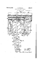
- Figure 1 is an elevation of two adjacent louvers mounted on the side of a vehicle'with certain parts broken away, 7
- Flgure 2 is a .section through a panel on the line 22of Figure 1,
- Figure 3 is asectionthrough a bracket on the line8'3 of Figure 1,
- Figure 4 is a perspectiveview of; a bracket,
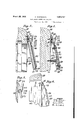
- Flgure 5 is a section similar. to Figure 2 of a modification, and
- F'gurefi is an elevation partly in section-- rail 10 and thepillars 11. Thesebrackets, preferably, take the form :of sheet metal stainpings of steel, so as to ensureiadequate strength with economyin manufacture.
- the bracket 12 which is situated between the two windows isof rectangularchannel section, see especially Figure 4 with a flange l3 directed outwardly from each lip of the channel.
- the depth of the channel is progressivelyv decreased as shown at 14 and the flanges 13 are inclined to the general plane of the body part of the channel.
- the sloping portion 14 of the base of the channel merges into a portion 15 which lies in the same plane as the inclined portions of the flanges, and said inclined portions are secured to the cant-rail 10 by screws 16 so that the bracket is inclined outwardly away. from the cant-rail at a suitable angle, say 1520, as shown in Figure 3.
- the flanges 13 are extended beyond the channel portion and their end portions are turned up at right anglestothe flanges to form lugs 17. These upturned lugs are about the same length as the depth of the channel. lVhen this bracket is thus mounted on the cant-rail, the open side of the channel faces the side of the vehiole;
- a further support for the bracket is provided by a screw 18 passing through it near its lower end and screwed into the pillar 11.
- a distance sleeve 19 surrounds the screw and constitutes an abutment against which the bracket is drawn by the screwing in of the said .screw.
- a recess 20 is formed in the base of the channel of such a shape as to engage theliead of the screw 18 squarely when it is screwed in at right-angles to the plane of the pillar 11.
- this bracket provides on each side of it a surface on the flange 13 on to which a panel 21 is laid, and a surface on the side wall 22 of the channel against which the ed of the panel 21 can abut.
- the lug 1 provides an abutment for the lower edge of the panel, and there is provided on this abutment a resilient packing, such as a block of rubber 23, against which the panel is pressed so as to maintain the packing in compression. 1
- a series of brackets of this type are provided for the various windows of the vehicle, and at the two ends the brackets are similar exce t that one flange 13 is omitted.
- One end brac et is shown at 24 in Figure 1.
- the panels 21 are preferably of sheet glass, and the upper edge of each sheet is mounted in a metal holder which extends throughout the full ength of the sheet, any suitable packing 25 being interposed as is usual.
- the holder is formed in two separate parts 26, 27.
- the part 26 is shaped to provide a gutter 28 and one limb 29 of a channel to receive the upper edge of the glass panel and is secured to the cant-rail 10 by screws 43.
- the other part 27 is a metal strlp which is pressed out to provide the other limb 30 of said channel and a.
- the part 27 of the holder is screwed on to the cant-rail 10 by screws 33, and it will be appreciated that the location of this part determines the location of the part 26 and, therefore, of the lower edge of the panel which is pressed against the resilient acking' 23.
- the part 26 of the channel is of such a length that it overlaps the brackets 12 but the part 27 is made in separate strips and recesses 34, see especially Figure 4, are provided in the flanges 13 of the brackets to accommodate the parts of the ends of said strips which lie in the same plane as the portion 15 of the bracket. These recesses serve to locate the holder and the panel in the desired position on the bracket when assembling the Whole device.
- cover-plates 35 which may be nickelplated or otherwise made of pleasin ap earance, can be secured to each brac keth 'a pair of screws 36 engaging the bracket.
- y convenient locking means may be provided at the back of the base of the channel-porti on of the bracket, such as a locking-plate 37 the upper edge of which is held in place by a lip 38 depressed out of the channel.
- the cover-plates 35 may be in the form of flat plates, in the case of double-sided brackets, although preferably they are provided with an overhanging lip 39 to conceal the lower end of the bracket.
- coverplate for an end bracket such as 24, may be provided with a side wall of triangular shape, as shown at 40 in Figure 6 and hereinafter referred to, to conceal the side of the bracket and close thegap between the bracket and the pillar 11.
- Strips of packing 41 are arranged alon the side edges of the panel 21, and between t ese stri s and the strip 25 corner pieces 42 of pac in'g'are provided.
- the packing is shown as projecting beyond the coverplates 35. This has been done in order to show the packing clearly; generally the packing will be concealed.
- the upper end of the panel is received in a metal channel 44 which is made in one piece comprising the gutter 28 and the two limbs 29, 30.
- This channel is secured to the cantrail 10 by screws similarly to'the part 26 of the two-part channel illustrated in Figures 1-3, and it will be appreciated that suitably shaped recesses are provided in its rear Wall to accommodate the upper ends of the brackets.
- Figure 6 shows a device according to the invention applied to a door 45 of a vehicle.
- the brackets 12 i are shaped and fixed in position as hereinbefore described with reference to Figures 1 4, and the upper end of the panel is mounted in a metal channel.
- the panel is held in position by a cover-plate which, is of ornamental cise constructional details described as they can be varied without departing from the in-' vention as defined'by the appended claims.
- a ventilating louver of the kind described the combination of a panel, two supporting brackets therefor which are adapted to be secured on opposite sides of a windowframe and which have surfaces on each bracket arranged to be engaged by a face and an edge of the panel respectively when the panel is laid on the brackets, a lug on the outer end of each bracket arranged to constitute an abutment for the outer longitudinal.
- a resilient packing interposed between the panel and said lug, and a holder made of substantially non-resilient material which is arranged to be secured to the window-frame and comprises a channel to receive the inner longitudinal edge of the panel, which holder is so positioned as to press the panel against the resilient packing I aforesaid.
- brackets and holder having interlocking parts which serve to locate the holder and the panel in the desired position on the brackets.
- a ventilating louver of the kind described the combination of a panel, supporting brackets therefor, which panel and supporting brackets are independent of one another, and a saparate holder for maintaining thepanel in place but permitting ready removal thereof, which holder comprises two channels whereof one is'shaped to constitute a gutter extending lengthwise of the panel and the other to receive one edge of the panel.
- porting fbrackets are independent of one another, and .a separate holder formaintaining the panel; in place but, permitting ready reinoval thereof, --whichholder is arranged to besecured to a window-frame and isformed by two separate parts whereof one part is Shaped to form .a gutter and to provide one side limb of a channel in which'an edge of the panel isreceived and the other part is shaped to provide the other limb ofthe channel and hasa projection arranged to enter a recess in the first-rnentioned part for locating purposes.
- a ventilating louver of the kind de scribed comprising in combinationa glass panel, two supporting brackets therefor in the form, of sheetmetal stampings, .a holder formed with'a channel to receive an edge of the panel, and cover-plates detachably'mounted on said brackets for the purpose set forth.
- a ventilating louver of the kind described comprising in combination a glass panel, two sheet metal supporting brackets therefor each havinga lug to constitute an abutment for the lower longitudinal edge of V the panel and a surface on which the panel rests, a two-part holder whereof one part is shaped to provide a gutter extending lengthwise of the panel and the other part has interlocking engagement'with the brackets and I laid on said bottom walls from the front of thelouver between the said side walls of the Y brackets, an abutment on each bracket for the outer longitudinal edge of the panel, a separate resilient packing interposed between the panel and said abutment,- and a metal channel in which the opposite longitudinal edge of the glass panel is received, which metal channel is secured to the window frame in such a position as to press the panel against said resilient packing.
- a ventilating louver of the kind described the combination of .a panel, a supporting bracket therefor which is situated at one end of the panel and is spaced away from the window'frame so that agap is left between the end of the panel and the front face of the window, and a cover mounted on said bracket and provided with aside wall to close said gap, for the purpose specified,
- each bracket adjacent to its lower and outer end whereby said bracket is attached to the window frame and spaced away from-the frame, a rectangular panel laid between the two brackets, a bottom wall along the length of each bracket, which bottom walls underlie the panel adjacent to the two opposed side edges thereof, a side wall on each bracket for preventing movement of the panel between the brackets, means for clamping the panel down against the bottom walls of the brackets, said means comprising cover plates removably attached one to each bracket and overlying the panel adjacent to the two opposed side edges thereof, a holder attached to the window frame and engaging the upper longitudinal edge of the panel, and lugs on the brackets engaging the bottom longitudi- 2b nal edge of the panel.
Description
March 22, 1932. A WATKINSON 1,350,737
VENTILATING LOUVER FOR WINDOWS Filed Feb. 26, 1930 2 Sheets-Sheet 1 z Fig.1. 3 10 March 22, 1932. WATKINSON 1,850,737
VENTILATING LOUVER FOR WINDOWS Filed Feb. 26, 1950 2 Sheets-Sheet 2' Patented 'Mar. 22,1 1932:
rssam UNITEDJSTATESI PATEN-r QTFEICE.
ARTHUR WATKINSON, or WEMBLEY, ENGLAnn, ASSIGNOR 'rornoxnrr, LAYCOGK & p
in'place on the window-frame andthe panel. '25
WATKINSON' LII'III'IED, OF LONDGN, ENGLANIQ'ABRITISH COMPANY VENTILATING-LOUVER roe wnvnows Application filed Fe bruary 26, 1930, Serial No. 431,613, and in Great Britain March 12,1929.
This invention is for improvements in or relating to windows, and'has for its object to provide an improved construction of ventilating louver of the kind which is used in conjunction with a sliding window, being situated at that end of the path of movement fromwhich the sliding window moves when it is being opened. The louverwhichis generallysomewhat inclined to the plane of the window, overlaps part of the path of .movement of the window so that with a small amount of openingof the window, a tortuous path is provided which gives ventilation without draught. Windows "fitted with such louvers :are customarily used on vehicles, but
it will be appreciated that their use is not thus limited.
'The present invention. comprises a ventilating louver of the kind above described,
comprising a panel and supporting brackets, whereinithep-anel and its supporting brackets are independent of one another and so constructed that the supports can be mounted subsequently detachably secured to them.
According'to a'further feature of this invention, a ventilating louver .of the type described comprises two brackets which are adapted to be secured on opposite sidesofthe window frame, and which are of open angle section facing one another to 1 provide sure,
faces on each bracket to engage a'face and an edge ofthe panel respectivelywhen the panel is laid on the brackets. i
According to another feature of the invention each bracket may be provided at its outer end with an upstanding lugto constitute an abutment for the outer edge of the panel, with o-rwithout a resilient packing interposed "between the ipanel and the lug, and with or without means for maintaining said packing in compression.
When a louver according to the present inventionis-provided with a glass panel, the upper edge-may bemounted in a metal channel which is secured to the window frame,
and is so positioned as to press the panel against the resilient packing. aforesaid at the outer end ofithe brackets. f
According to a further featureof the vention, the bracket or the channel is provlded with a recess to accommodate apart of the channel or of the bracket respectively,
invention, there is provided a gutter which extends lengthwise of the panel- There will now be described with reference to the accompanying drawings, a particular, construction of ventilating, louver embody ing the above-mentioned principal features of the invention, and also certain-other novel details, it being understood, however, that this description is given merely by way of an example of the present invention.
In the drawings Figure 1 is an elevation of two adjacent louvers mounted on the side of a vehicle'with certain parts broken away, 7
Figure 3 is asectionthrough a bracket on the line8'3 of Figure 1,
Figure 4 is a perspectiveview of; a bracket,
Flgure 5 is a section similar. toFigure 2 of a modification, and
F'gurefi is an elevation partly in section-- rail 10 and thepillars 11. Thesebrackets, preferably, take the form :of sheet metal stainpings of steel, so as to ensureiadequate strength with economyin manufacture.
The bracket 12 which is situated between the two windows isof rectangularchannel section, see especially Figure 4 witha flange l3 directed outwardly from each lip of the channel. At the upper end'of the bracket, the depth of the channel is progressivelyv decreased as shown at 14 and the flanges 13 are inclined to the general plane of the body part of the channel. The sloping portion 14 of the base of the channel merges into a portion 15 which lies in the same plane as the inclined portions of the flanges, and said inclined portions are secured to the cant-rail 10 by screws 16 so that the bracket is inclined outwardly away. from the cant-rail at a suitable angle, say 1520, as shown in Figure 3. At the lower end of the bracket, the flanges 13 are extended beyond the channel portion and their end portions are turned up at right anglestothe flanges to form lugs 17. These upturned lugs are about the same length as the depth of the channel. lVhen this bracket is thus mounted on the cant-rail, the open side of the channel faces the side of the vehiole;
A further support for the bracket is provided by a screw 18 passing through it near its lower end and screwed into the pillar 11. A distance sleeve 19 surrounds the screw and constitutes an abutment against which the bracket is drawn by the screwing in of the said .screw. Preferably, a recess 20 is formed in the base of the channel of such a shape as to engage theliead of the screw 18 squarely when it is screwed in at right-angles to the plane of the pillar 11.
It will be seen that this bracket provides on each side of it a surface on the flange 13 on to which a panel 21 is laid, and a surface on the side wall 22 of the channel against which the ed of the panel 21 can abut. Also, the lug 1 provides an abutment for the lower edge of the panel, and there is provided on this abutment a resilient packing, such as a block of rubber 23, against which the panel is pressed so as to maintain the packing in compression. 1 A series of brackets of this type are provided for the various windows of the vehicle, and at the two ends the brackets are similar exce t that one flange 13 is omitted. One end brac et is shown at 24 in Figure 1.
The panels 21 are preferably of sheet glass, and the upper edge of each sheet is mounted in a metal holder which extends throughout the full ength of the sheet, any suitable packing 25 being interposed as is usual. In the construction shown in Figures 13, the holder is formed in two separate parts 26, 27. The part 26 is shaped to provide a gutter 28 and one limb 29 of a channel to receive the upper edge of the glass panel and is secured to the cant-rail 10 by screws 43. The other part 27 is a metal strlp which is pressed out to provide the other limb 30 of said channel and a.
In order to secure the panel in position and to enhance the appearance of the whole device, cover-plates 35 which may be nickelplated or otherwise made of pleasin ap earance, can be secured to each brac keth 'a pair of screws 36 engaging the bracket. y convenient locking means may be provided at the back of the base of the channel-porti on of the bracket, such as a locking-plate 37 the upper edge of which is held in place by a lip 38 depressed out of the channel. The cover-plates 35 may be in the form of flat plates, in the case of double-sided brackets, although preferably they are provided with an overhanging lip 39 to conceal the lower end of the bracket. Similarly, the coverplate for an end bracket, such as 24, may be provided with a side wall of triangular shape, as shown at 40 in Figure 6 and hereinafter referred to, to conceal the side of the bracket and close thegap between the bracket and the pillar 11.
Strips of packing 41 are arranged alon the side edges of the panel 21, and between t ese stri s and the strip 25 corner pieces 42 of pac in'g'are provided. In Figure 1, the packing is shown as projecting beyond the coverplates 35. This has been done in order to show the packing clearly; generally the packing will be concealed.
In the modification illustrated in Figure 5, the upper end of the panel is received in a metal channel 44 which is made in one piece comprising the gutter 28 and the two limbs 29, 30. This channel is secured to the cantrail 10 by screws similarly to'the part 26 of the two-part channel illustrated in Figures 1-3, and it will be appreciated that suitably shaped recesses are provided in its rear Wall to accommodate the upper ends of the brackets. I
Figure 6 shows a device according to the invention applied to a door 45 of a vehicle. In this construction, the brackets 12 i are shaped and fixed in position as hereinbefore described with reference to Figures 1 4, and the upper end of the panel is mounted in a metal channel. The panel is held in position by a cover-plate which, is of ornamental cise constructional details described as they can be varied without departing from the in-' vention as defined'by the appended claims.
I claim: 1. Ina ventilating louver of the kind described, the combination of a panel, two supporting brackets therefor which are adapted to be secured on opposite sides of a windowframe and which have surfaces on each bracket arranged to be engaged by a face and an edge of the panel respectively when the panel is laid on the brackets, a lug on the outer end of each bracket arranged to constitute an abutment for the outer longitudinal.
edge of the panel, a resilient packing interposed between the panel and said lug, and a holder made of substantially non-resilient material which is arranged to be secured to the window-frame and comprises a channel to receive the inner longitudinal edge of the panel, which holder is so positioned as to press the panel against the resilient packing I aforesaid.
2. In a ventilating louver of the kind described, the combination of a panel, supporting brackets therefor, which panel and supporting brackets are independent of one another, and a separate holder for maintain,
ing the panel in place but permitting ready, removal thereof, which holder comprises a channelto receive one edge of the panel;
said brackets and holder having interlocking parts which serve to locate the holder and the panel in the desired position on the brackets.
3. In a ventilating louver of the kind described, the combination of a panel, supporting brackets therefor, which panel and supporting brackets are independent of one another, and a saparate holder for maintaining thepanel in place but permitting ready removal thereof, which holder comprises two channels whereof one is'shaped to constitute a gutter extending lengthwise of the panel and the other to receive one edge of the panel.
4. In a ventilatinglouver of the kind described,the combination of a panel, supporting brackets therefor, which'panel and sup:
. porting fbracketsare independent of one another, and .a separate holder formaintaining the panel; in place but, permitting ready reinoval thereof, --whichholder is arranged to besecured to a window-frame and isformed by two separate parts whereof one part is Shaped to form .a gutter and to provide one side limb of a channel in which'an edge of the panel isreceived and the other part is shaped to provide the other limb ofthe channel and hasa projection arranged to enter a recess in the first-rnentioned part for locating purposes.
5. A ventilating louver of the kind de scribed, comprising in combinationa glass panel, two supporting brackets therefor in the form, of sheetmetal stampings, .a holder formed with'a channel to receive an edge of the panel, and cover-plates detachably'mounted on said brackets for the purpose set forth.
6. A ventilating louver of the kind described, comprising in combination a glass panel, two sheet metal supporting brackets therefor each havinga lug to constitute an abutment for the lower longitudinal edge of V the panel and a surface on which the panel rests, a two-part holder whereof one part is shaped to provide a gutter extending lengthwise of the panel and the other part has interlocking engagement'with the brackets and I laid on said bottom walls from the front of thelouver between the said side walls of the Y brackets, an abutment on each bracket for the outer longitudinal edge of the panel, a separate resilient packing interposed between the panel and said abutment,- and a metal channel in which the opposite longitudinal edge of the glass panel is received, which metal channel is secured to the window frame in such a position as to press the panel against said resilient packing.
8. In a ventilating louver of the kind described, the combination of .a panel, a supporting bracket therefor which is situated at one end of the panel and is spaced away from the window'frame so that agap is left between the end of the panel and the front face of the window, and a cover mounted on said bracket and provided with aside wall to close said gap, for the purpose specified,
9. The combination in a ventilating louver of the kind described of two support brackets spaced apart and attached to the window frame at their upper. ends, which brackets extend outwards and downwards away from;
the frame below their attachment to it, a support for each bracket adjacent to its lower and outer end whereby said bracket is attached to the window frame and spaced away from-the frame, a rectangular panel laid between the two brackets, a bottom wall along the length of each bracket, which bottom walls underlie the panel adjacent to the two opposed side edges thereof, a side wall on each bracket for preventing movement of the panel between the brackets, means for clamping the panel down against the bottom walls of the brackets, said means comprising cover plates removably attached one to each bracket and overlying the panel adjacent to the two opposed side edges thereof, a holder attached to the window frame and engaging the upper longitudinal edge of the panel, and lugs on the brackets engaging the bottom longitudi- 2b nal edge of the panel.
In testimony whereof I afiix my signature.
ARTHUR WVATKINSON.
Applications Claiming Priority (1)
| Application Number | Priority Date | Filing Date | Title |
|---|---|---|---|
| GB1850737X | 1929-03-12 |
Publications (1)
| Publication Number | Publication Date |
|---|---|
| US1850737A true US1850737A (en) | 1932-03-22 |
Family
ID=10891952
Family Applications (1)
| Application Number | Title | Priority Date | Filing Date |
|---|---|---|---|
| US431613A Expired - Lifetime US1850737A (en) | 1929-03-12 | 1930-02-26 | Ventilating-louver for windows |
Country Status (1)
| Country | Link |
|---|---|
| US (1) | US1850737A (en) |
Cited By (1)
| Publication number | Priority date | Publication date | Assignee | Title |
|---|---|---|---|---|
| US2746373A (en) * | 1953-10-02 | 1956-05-22 | Mary E Bergsten | Window guard and ventilator |
-
1930
- 1930-02-26 US US431613A patent/US1850737A/en not_active Expired - Lifetime
Cited By (1)
| Publication number | Priority date | Publication date | Assignee | Title |
|---|---|---|---|---|
| US2746373A (en) * | 1953-10-02 | 1956-05-22 | Mary E Bergsten | Window guard and ventilator |
Similar Documents
| Publication | Publication Date | Title |
|---|---|---|
| US4282919A (en) | Interior storm window | |
| US2321554A (en) | Supplementary sash and frame for window openings | |
| US2826282A (en) | Horizontal sliding window structure and frame therefor | |
| US2869187A (en) | Sliding type window construction | |
| US2270978A (en) | Light-tight shade construction | |
| US2386380A (en) | Tropical louver construction | |
| US2283009A (en) | Sliding window construction | |
| US2193852A (en) | Window construction | |
| US1850737A (en) | Ventilating-louver for windows | |
| US2338192A (en) | Closure device for handholes or openings | |
| US2204769A (en) | Windshield frame | |
| US3222734A (en) | Storm window and screen installation for existing standard window frame structure | |
| US3605341A (en) | Portable sliding windows for automobiles | |
| US2304640A (en) | Window regulator | |
| US2226833A (en) | Bulletproof glass mounting unit | |
| US2635523A (en) | Ventilator sash unit | |
| US2915119A (en) | Automobile window screen | |
| US2615515A (en) | Window screen for automobiles | |
| US2435008A (en) | Storm window ventilating and cleanout opening | |
| US2274824A (en) | Window ventilator wing | |
| US2126167A (en) | Panel mounting | |
| US2192651A (en) | Weather stripping and the like | |
| US2034849A (en) | Visor nested in recess of header panel | |
| US2236615A (en) | Wind deflector | |
| US1813768A (en) | Window shade mounting |