US1850177A - Fire alarm system - Google Patents
Fire alarm system Download PDFInfo
- Publication number
- US1850177A US1850177A US339032A US33903229A US1850177A US 1850177 A US1850177 A US 1850177A US 339032 A US339032 A US 339032A US 33903229 A US33903229 A US 33903229A US 1850177 A US1850177 A US 1850177A
- Authority
- US
- United States
- Prior art keywords
- relay
- circuit
- armature
- switch
- code
- Prior art date
- Legal status (The legal status is an assumption and is not a legal conclusion. Google has not performed a legal analysis and makes no representation as to the accuracy of the status listed.)
- Expired - Lifetime
Links
Images

Classifications
-
- G—PHYSICS
- G08—SIGNALLING
- G08B—SIGNALLING OR CALLING SYSTEMS; ORDER TELEGRAPHS; ALARM SYSTEMS
- G08B26/00—Alarm systems in which substations are interrogated in succession by a central station
Definitions
- the present invention relates in general to signaling systems but is more particularly concerned with a signaling system adaptable for use as a fire alarm system; and the principal object, broadly stated, is the provision of a fire alarm system of the type suitable for use in rural communities or small towns ⁇ A further object is the provision of a simple re alarm system that is inexpensive in construction, that will operate efficiently at all times, and in addition require a minimum amount of maintenance.
- Another object resides in the utilization of a comparatively slow operating sound producing apparatus such as a siren which may be mounted at a centrally located point in a community, together with a plurality of fastoperating fire alarm pull boxes scattered throughout the district for operating the siren.
- a system is provided wherein there are a number of separate lines with a plurality of fire alarm pull boxes arranged on each linen and with each box on the line arranged so that it will rapidly transmit a particular single-digit' code to the exchange apparatus. This single-digit code is automatically translated at the exchange into a comparatively slow two-digit code in order to operate the siren.
- An important feature of the invention resides in the means whereby the fire alarm box transmits a single-digit code only once and this is translated into a two-digit code by the exchange apparatus and repeated any desired number of times on the siren.
- Fig. 1 should be placed to the left of Fig. 2 and Fig. 3 immediately below Fig. 2.
- Fig. 4 is a separate sheet.
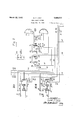
- Fig l shows a plurality of fire alarm pull boxes on a line L1 extending to the exchange apparatus and terminating in the line switch circuit LS1 individual thereto.
- a numberof keys and other apparatus shown in this figure are for testing the various lines.
- Fi 2 illustrates the station circuits SG1 and C6 individual to the fire alarm boxes #24 and #32 of Fig. l, and the code cut-oil' switch CO which determines the number of times the code is to be repeated on the siren.
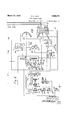
- Fig. 3 shows a code switch CS which selects the proper code of the operated iire alarm station, and the timing switch TS which controls the operation of the siren SR in accordance with the selected code.
- the group of relays shownin this ligure control the operation of both switches.
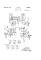
- Fig. 4 shows a modification of Fig. 1 with two sets of vline switch circuits connected to a single line, one for the odd fire alarm stations and the other for ⁇ the even fire alarm stations.
- the system disclosed in the invention com'- prises ten fire alarm lines with ten stations on each line, making a 10U-station fire alarm system.
- One of the lines L1 is shown in Fig. l having two fire alarm stations #24 and #32 connected in series therein. It will be understood, of course, that there are eight other stations on the same line.
- Another line L2 is also shown leading to the exchange. These lines terminate in keys K1, K2, etc.,
- the line L1 which it will be noted is a normally closed loop extending in series through all.
- This switch LS1 is individual to the line L1 and comprises a group of relays controlled from any re alarm box on this line.
- This switch is of well-known construction and is illustrated and described in the book Automatic Telephony Smith and Campbell, published by the Mcgraw-Hill Book Co., page 94. In general it comprises a wiper 17 which is adapted to be rotated over a plurality of bank contacts, 1 to 10, under control of a stepping magnet 16. After it has been operated it is automatically restored to normal position under the/control of the release magnet 14.
- the bank contacts of the switch correspond to the stations on the line L1; for example, if station #24 is operated the line switch will operate one step and engage its first contact because the cam at station #24 has only one tooth on it. Accordingly, the wiper 17 rests on the iirst contact to which the wire 21 is connected.
- This conductor leads into the station circuit SG1, Fig. 2. This comprises a group of relays and a lamp A1 indicating the num'- ber of the calling station. Each fire alarm station on the line and in the system has one of these station circuits individual to it.
- the relays of each station circuit provide for the storing of the alarm, selecting and starting the code to be blown on the siren, and preventing interference between alarms, Once a fire alarm station has operated, all other stations in the system are prevented from sending in an alarm until this station has finished operating, the codes of the other operated stations being stored temporarily in the relay group or station circuit SC individual to that station.
- a code-cutoil switch CO which is used for determining the number of times the siren is to be operated.
- This switch is of well-known construc- ⁇ ⁇ 5 normal position.
- the group of relays to the left of the switch CO are provided for starting the alarm and also for other purposes to be described.
- Fig. 3 two sets of switches are shown, one the code switch CS and the other the timing switch TS. These are similar in construction and operation to the code cut-off switch CO of lig. 2.
- the code switch CS determines the proper code to be blown on ⁇ the siren. This is a two-digit code which has been translated by the associated station circuit over the wires connected to the bank contacts of the code switch. One-hundred different codes can be selected on the code switch CS, although only two have been shown.
- the timing switch TS controls the code switch and provides the proper timing arrangement so that the siren can be operated properly in accordance with the operated ire alarm station code.
- the group oi relays to the left of the timing switch TS control the proper operation of the code switch and the timing switch and also pro- Vide the proper time interval between each blast of the siren and also the code.
- the siren SR is illustrated in the lower left-hand corner of this ligure and is controlled by a pair of relays. The operation of one of these relays closes they circuit to one winding of the siren motor which operates the ing such as the court house, or in such a position that it will bc heard from all fire alarm stations connected to the system.
- A'printing magnet PR is also connected in the circuit of the siren so as to print a. permanent record of the station sending in an alarm.
- Relay 5 due to the copper slug on its heel end, does not release when a series of rapid interruptions have been produced in lll) its circuit and therefore its armatures 6 and 7 operated. At the first interruption relay 10, however, falls back and closes its arma,
- the offnormal contacts 13 Upon the first operation, or rst step, of the stepping magnet 16 and the movement of the wiper 17 to the first bank contact, the offnormal contacts 13 became operated and prepared a circuit for the release magnet 14. After relays 15 and 2O have completely deenergized, a circuit is closed over a path extending froml ground on armature 9 and its back contact, armature 12 and its back contact, off-normal springs 13, through the winding of release magnet 14 to battery. The release magnet 14 operates and restores the wiper ⁇ 17 to its normal position. When the wiper reaches its normal position, the offnormal contacts 13 are opened permanently.
- Relay 25 is operated from the ground through wiper 17 and closes its armature 26 to its front contact and completes a locking circuit for itself extending from ground at armature and back contact 29, armature 26 and its front contact through the winding of the relay to battery.
- armature 27 and its front contact a circuit is completed for the station circuit lamp A6, the lighting of which thereby indicates the operation of the associated fire alarm box #32.
- relay 25 opens the chain circuit extending through conductor 44 and through all station circuits in the system, thereby preventing any other re alarm box from operating the exchange apparatus to send in a code at this time. It maybe stated at this time that the conductors 41 to 45, inclusive, extending to the top of Fig.
- Relay 35 energizes in this circuit 'and at its front Contact and armature 37 completes a locking circuit for itself extending from ground on the back contact of armal ture 29, armature 37 and its front contact, through the lower Winding of relay 35, over conductor and through the winding of relay to battery.
- Relay 50 energizes in this circuit and at the back contact of armature 48 opens the circuit through conductor 43 which was the original energizing circuit of relay 35. At the front contact of armature 48 an obvious circuit is completed through the winding of relay to ground.
- Relay 55 upon energizing, at grounded front contact of armature 56, places ground through normally operated armature 58 to conductor 46.
- the normally open back contact of armature 58 to which conductor 57 is connected extends to a similar piece of apparatus as conductor 46; in other words, to another code sender.
- Relay- 6() has its circuit normally taken through key K6 to ground. Should it happen that one code sender is not operating properly or is faulty, the key K6 is operated by an attendant, thereby releasing relay 60 and over conductor 57 connecting another code sender to the circuit.
- Relay 125 operates its armatures and places ground on armature spring 126 and its front contact over a circuit extending trom armature 127 and its front contact, wiper 163 of the code switch (JS, its irst bank contact 164 upon which the wiper is normally resting, armature 132 and its front contact, through the winding of relay 130 to the non-inductive resistance to battery.
- Relay 130 oper'ates in this circuit and at its armatures 133 and 134 prepares a circuit for the relays 135 and 140 which control the operation of the siren SR.
- relay 130 completes a locking circuit for itself, extending directly to the armature 126 to ground.
- relay 125 also completed a circuit extending over armature 111 and its back Contact through the winding of slow-to-pull-up relay 100 to battery.
- the high resistance and noninductive winding connected to battery'in parallel of relay 100 assists in making this relay slower to pull up.
- Relay 100 slowly energizes and at its front contact and armature 101 completes a circuit extending over the previously mentioned path tothe winding of relay 105 to battery. After an interval, relay 105 becomes energized and at its front Contact and armature 106 completes a circuit over the same path but extending through the armature 116 and its back contact, back contact and armature 117 of relay 115, through the winding of relay 110 to battery.
- Relay 110 energizes and at its back Contact' and armature 111 opens the circuit for relay 100.
- a circuitin parallel with the circuit of relay 110 extends from the back contact of armature 116 to the winding of the rotary ⁇ stepping magnet 150 of the timing switch TS whereupon it energizes.
- relay 100 opens the circuit of relay 105.
- Relay 105 upon falling back, at its front contact and armature 106 opens the circuit over armatures 116 and 117 of rerelay 110 and this relay falls back.
- Vhen armature 106 opens'its front contact, the circuit to the rotary stepping magnet 150, which is connected in parallel with relay 110, also be came opened and the magnet is deenergized, thereby stepping the wipers 152, 153. and 154 of the switch TS from their first bank contact or their normalposition on to the second set of bank contacts.
- relay 110 Upon the deenergization of relay 110, at armature and contact 111 it again completed a circuit for slow-to-pull-up relay 100. This relay in turn again completes the circuit of relay 105, and at front Contact of armature 106 relay 105 again completes a circuit for relay 110 and rotary stepping magnet 150 in multiple therewith. Stepping magnet 150 againenergizcs and relay 110 separates its armature from its back contact 111 to open the circuit of relay 100. Relay 100 at its armature 101 opens the circuit of relay 105.
- relay 105 Upon the deenergization of relay 105, it opens the armature 106 from its front contact to interruptthe circuit of relay 110 and the rotary stepping magnet 150. Stepping magnet 150 falls back and advances the wipers 152,
- Relay 110 upon again falling back ⁇ at its armature and back contact 111 recloses the circuit for slow-topull-up relay 100, and the cycle of operations resulting in the energization and deenergization of relays 100, 105, 110 and the rotary stepping magnet 150 continues until the wiper 154 of the timing witch TS reaches the seventh bank contact During this period while the ste ping magnet 150 was rotating the wipers otP TS over the bank contacts, the siren SR was being operated to send out a blast on its siren.
- the circuit extends over Wiper 152 from ground through the bank contacts over which this wiper is stepping, armature 133 and its front contact, through the winding of relay 140 to battery.
- the bank contacts of the code switch CS over which wiper 163 rotates lead over conductors extending to all the station circuits; the first half of this bank, conductors 1 to 10, representing the tens digit of the code, while the remaining half of the bank to which conductors 1 to 10 are attached represents the units digit of the code, so that whenever' a station circuit, in this case SCG, has been operated due to the operation of the associated fire alarm box #32, the armature springs 38 and 39'of relay 35, Fig. 2, have their front contacts closed, thereby completing a circuit extending from battery through slow-release relay 120, Fig.
- the rotary stepping magnet 150 continues to automatically interrupt itself and step the wipers 152, 153, and 154 rapldly over their bank contacts.
- a circuit is again completed from ground on armature '152.
- Relay 140 upon operating its :wn-rature 138 again starts the motor of the siren SR and sends out blasts.
- the wiper 1.53 of the timing switch reaches its bank contact 148 and the circuit i' or slow-release relay 115 is interrupted and, upon falling away, opens its armature 118to open the self-interrupting circuit of the stepping magnet 150 and at its armatures 116 and 117 again closes the automatic slow stepping operation of relays 100, 105, and 110 and stepping magnet 150.
- the timing switch TS continues to step in this manner and the siren to sound the blasts until the bank contact 156 ofthe wiper 154 is reached. Atthis time another circuit is completed from ground over Wiper 154, bank contact 156, through the winding of stepping l magnet 160 of the code switch CS to battery.
- the wiper 154 has steppedoii' of bank contact 156 the stepping magnet 160 deenergizes, advancing its wipers 162 and 163' the second step.
- the #2 bank contact connected to wiper 163 has no potential connected to it from an operated re alarm station, 'no
- the timing switch TS continues to operate under the control of relays 100, 105 and 110 and stepping magnet
- the timing switch TS is stepped fast be-l cause of the self-interrupting circuit for the magnet 150 which extends overthe wi er 153 l and relay 115, and then slow again as efore, until its wiper 154 encounters bank contact 155. At this time a circuit is again completed Ifrom ground on wiper 154, bank Contact 155,
- a short circuit for relay 1305 is completed extending over armature and front contact 128 of relay 125, through the non-inductive winding in multiple of the relay- 130 to battery.
- the other side of the winding of relay 130 extends to ,its own locking circuit at armature 136 to round at armature 126.
- Relay 130 is therey short circuited and released.
- the timing switch TS continues to step as it has before.
- the circuit for slow-release relay 120 extending to its lockingvcontact 123 and the stepping circuit for the interrupting magnet 160 extending through armature sprin s and contact 124 is interrupted, and the co e switch comes to rest.
- Relay 120 upon deenergizing, opens its contact 123 which has locked itself up, and at armature spring 122 removes the short circuit of relay 130 extending to the high resistance to battery.
- relay 120 completes the self-interrupting circuit for the .stepping magnet 16() extending from ground on the bank contacts of the code switch, wiper 162, front contact and armature 124, interrupter contacts 161, through the winding of stepping magnet 160 to battery.
- the stepping magnet continues to step the code switch CS at a comparatively fast rate of speed over its bank contacts.
- relay 120 again short circuits relay 130 over front contact and armature 128 ofrelay 125.
- Relay 130 upon deenergizing, opens the circuit extending to the siren over armatures 133 and 134 to stop the siren from sending out a blast.
- the code switch continues to step until its Wiper 163 reaches its bank contact 166.
- the code cut-oit switch CO will be operated to ⁇ rotate its wipers over the bank contacts one step over the abovetraced circuit.
- the timing switch TS has also energized relay 115 over wiper 153 and completed its locking circuit at. armature 118 to again complete the fast tact, the locking circuit for relay 120 extending through armature spring 123 is again opened, and this relay falls back and at armature 124 opens a fast self-interrupting circuit for the stepping magnet 160.
- the tim ing switch TS has reached the last bank contact rotated over by wiper 153, the circuit for slow-release relay 115 is interru ted, thereby stopping the fast operation o the stepping magnet 150.
- the code switch CS and the timing switch TS are now in a position to again sound the code of the called fire alarm station #32 in the same manner as has been previously described; the code switch CS has non7 completed four revolutions of its Wipers 162 and 163 over the bank contacts, the code of the fire alarm station #32 has been sounded four times on the siren, While the code cut-off switch CO (Fig. 2) has reached its fourth bank contact 79 on which Wiper 77 is resting. ⁇
- a circuit is 110W completed extending from ground on wiper 77, bank contact 7 9 u on Which it is now resting, through the winding of relay 70 to battery.
- re ⁇ lay 7 0 closes its armature 72 on its front contact and completes a circuit extending from ground, armature 72 and its front contact, through the resistance ⁇ 68, tothe Winding of slow-release relay 65, bank contacts upon which wiper 78 is resting, through wiper 7 8, back contact of armature 76 of the stepping magnet 75, through the Winding of this magnet tobattery.
- 2Relay 65 upon energizing, closes a locking circuit for itself over its front contact and armature 67, shunting out the resistance 68. Stepping magnet 75 thereby steps the code cut-ofi' switch over its bank contacts until the last one is reached and the circuit for the stepping magnet 75 and the slow-release relay is opened, and the code cut-off switchis nonT in normal position.
- relay 0 completes a locking circuit for itself extending from ground on front contacts and armature 66, armature 71 and its front Contact, through the Winding of relay to battery.
- ground is removed from the conductor 44 which extends over armature 28 of relay 25 of the station circuit SCG ⁇ front Contact of armature 28, back contact and armature 32, through the upper Winding of relay 35, conductor 43, to battery at armature 48.
- relay 70 completes a circuit extending from ground on armature 73 and its front contact, conductor 42, armature 36 and front contact of relay 35, through the Winding of relay 30 to battery.
- Relay 30 is thereby energized and locks up over front contact and armature 31, through the front contact and armature 27 of relay 25 to ground.
- relay 30 removes ground from the backcontact of armature 29, thereby opening the locking circuit of relays 25 and 35 which extended over their armatures 26 and 37, respectively.
- relay 25 cxtinguishes the station circuit lamp A6.
- the chain circuit extending over conductor 44 to all the station circuits in the system is again completed, so that another fire alarm call or code can be sent in.
- armatures 38 ⁇ and 39 upon deenergizing, opens the circuit of the units and tens digit extending over conductors 51 and 52 to the code switch CS.
- relay 35 opens the circuit of relay 50 with which it was energized in series from ground on armature 29.
- relay 35 opens the circuit of relay 30 and it falls back.
- Relay 50 upon deenergizing, places battery from armature 48 to its back contact on to conductor 43 in series with the relay 35 of the station circuit, which is now ready to receive another signal.
- slow-release relay 65 After slow-release relay 65 is fully re upon conductor 44, which conductor extends v in series with all the station circuits in the system.
- relay 50 opens the circuit of relay 55, and relay 55, upon restoring, opens its armature 56 from its grounded front contact to open the circuit extending ⁇ over front contact and armature 58, conductor 46, through the Winding of relay 125 to battery.
- Relay 125 decnergizes and at front contact and armature 129 the circuit of relay 120 is opened from the conductor 41.
- ground is removed from the circuit extending over armature 111 to relay 100 to prevent the further stepping of the switches. ⁇ All of the apparatus including the timing switch TS and the code switch CS has reached their normal position and are now ready to receive another call from. the fire alarm box.
- the siren has sounded the code of the fire alarm box #32 four times to arouse the community, While the printing magnet PR leaves a permanent lrecord of the call, and the illumination ofthe lamp A1 informs the at* tendant of the number of the station calling, which may be printed on a card adjacent the lamp. Hc consults a card record for the location of this fire alarm box and then dispatches the fire-fighting apparatus to the fire.
- the at; ⁇ tempt might be a mutilated code.
- the speed with which the cams 2 and 3 operate and the instant operation of the switch LS1 and the station circuit SC6 would practically eliminate this possibility.
- One or the other codes of the fire alarm boxes would be stored in the associated station circuit until the first code had been set out, when the apparatus would automatically send out that code ⁇ due to the closure of the loop circuit over conductor 44 between the station circuits.
- relay 115 extendving from ground on back contact and armature 126, first bank contactover which wiper 153 has been accidentally stepped, wiper 153, to the winding of relay 115 to battery.
- relay 115 closes its armature 118 on to its front contact and completes the automatic stepping circuit, until the wiper reaches its first contact, for stepping magnet 150 to return the switch back to its normal position.
- relay 15 As relay 5 falls back slowly, a circuit is also completed extending from ground through armature 8 and its back contact, through the winding of relay 15 to battery. Relay 15 energizes slowly and at its front contact and armature 9 completes a circuit for relay 20. In the meantime, however, the circuit of relay 5 has been opened and armature 6 has opened its front Contact, thereby opening the circuit of relay 15 and this in turn of relay 20. Relay' 20, however, does not have time to fully energize before its circuit is again opened at armatuie 6. This action prevents the possibility of sending in a false alarm.
- key K3 is restored and key K4 is operated to test for ground on the other side of the line.
- the key K4 is again restored and the key K5 operated. This places ground to the upper side of the key K5 on one side of the line and back over the other side of the line through all of the fire alarm stations on the line L1 through the lower side of key K1, K5, K4, and key K3 through the volt meter to battery B.
- the reading of the volt meter will indicate to the attendant the possibility of a short circuit out on the line.
- the key K5 is then restored to normal position as also is the key K1 after the trouble on the line has been corrected, if there has been any.
- the line L1, upon the restoration of the key K1, thereby is connected again to the line circuit LS1.
- the battery B is always normally connected in series with the volt meter V through the keys K3, K4, and K5 to ground. This gives a constant reading of the battery.
- This battery B is connected as indicated by the arrows, on one side to a source of charging current while the opposite side is connected to all the apparatus in the exchange, indicated by the battery and ground connections on the relays and various springs, which are indicated in all the figures in this manner merely for convenience. These battery and ground connections actually are connected in the exchange to the battery B.
- FIG. 4 this is a modication of Fig. 1 and can be inserted to take the place of this figure.
- one line circuit LS as in Fig. 1
- each fire alarm box is connected to a ground circuit through a normally opened spring at the fire alarm box.
- grounded impulses are sent out by the impulse springs from the oil'- normal springs which will be closed, and when the box is restored to normal position they will again open.
- the conductors 1 to 10 extending to the right of this figure from the bank contacts of the switch OLS and ELS, of which there are ten from each switch, will connect up in a similar manner as in Fig. 2 to the various station circuits SC. There will be twenty of these station circuits for each line. The twenty fire alarm boxes arranged on this line are associated with one another in such a manner that there will be an odd box between every two even boxes throughout the whole series. This is for a purpose which will be later explained.
- the series circuit of the line L3 extends from battery through relay 220 of the switch ELS through all the even-numbered fire alarm boxes in the line circuit, back through all the odd-numbered fire alarm boxes in series through the upper Winding of the diffcrential relay 200 to ground.
- the relay 200 is wound so that it remains deenergized in this circuit because current is owing through its lower winding and in series with its upper winding in a direction opposite to that flowing in its upper winding. The windings are therefore normally in opposition.
- Relay 220 will thus be normally energized or as long as there is no fire alarm being sent over the line.
- the ground at the fire alarm box #1 extending to the off-normal springs 204 also is -fed to the interrupter springs 203 and grounded impulses are, therefore, .fed over the line L3 through the lower winding of relay 200 to battery.
- the upper winding of this relay is therefore short-circuited and will have no eii'ect on its operation, and accordingly relay 200 energizes.
- At its front contact and armature 202 ground istransmitted through the upper and lower windings of relay 205 to battery.
- the lower winding of this relay is a non-inductive winding while the upper winding will be short circuited when the relay 200 restores its armature 202.
- relay 205 slow-to-release as is relay 210, for example, whichv has a copper sleeve on the heel end.
- relay 205 prepares a circuit for relay 210.
- a circuit is thereby ⁇ completed extending from ground on armature 202 and its back contact, front contact and armature 207 of relay 205, through the alternate closed contact of armature 211, throu h the winding of slow-release relay 210 to attery.
- Relay 210 energizes and at its front contact and armature 211 completes a locking circuit for itself extending to the ,front contacts and armatures 208 to ground on relay 205. Relays 205 and 210 remain in energized position during the transmission of the remaining impulses over the line circuit. Differential relay 200 will follow these interruptions in the line.
- relay 200 On the first energization of relay 200 it also closed ground on the front contacts of armature 201 and when relay 210 pulled up this ground was fed through armature 213 and its front contact through the winding of stepping magnet 217 to battery. Stepping inagnet 217 accordingly steps the ⁇ wiper 218 of the switch OLS in accordance with the energization and deenergization of relay 200 which corresponds to the interruption of the line circuit from the iire alarm box #1. After the interruptions from the fire alarm box #l have ceased, relay 200 will be deenergized and at the alternate contacts of armature 202 short circuit the upper winding of relay 205 and this relay falls slowly back.
- relay 205 removes ground from' the locking circuit of relay 210, and this relay falls backslowly, but relay 205 is already back, or falls back before relay 210 does, and a circuit is thereby completed extending from ground on armature 208 and its back contact, armature 212 and its front Contact, wiper 218 and the contact upon which it is now resting and which is associated with the code number of the odd station #1, through the conductors extending from this contact and then over the station circuit associated with the calling fire alarm box, which in this case will be similar to SG1 or SCG.
- the code of this box is then sent out by the-exchange apparatus. A short time afterward relay 210 will become com'- pletely deenergized.
- a circuit is thereby completed extending from ground on armature 208 and its back contact, armature 212 and its back contact, the off-normal springs 216, which were closed immediately upon the first step of the switch OLS and the advancement of the wiper 218 on to its first contact, and then through the winding of release relay 215 to battery.
- Release relay 215 operates and releases the wiper 218 which restores and opens the off-normal contacts 216, and the switch now is in normal position.
- Relay 235 upon energizing, at armature 236 opens a circuit extending to the wiper 243 which is associated with the even-numbered station circuit ELS. The reason for this will be later explained.
- Relay 210 of the switch OLS does not become energized because its circuit remains opened atthe back contact of armature 202 of relay 200. Grounded impulses will now be forwarded from the off-normal springs of fire alarm box #2, and over the line L3, through the Winding of relay 220 to battery. After the first impulse relay 220 retraets its armatures and at armature 221 and its alternate contact closes a circuit extending from ground through the upper and lower winding of relay 225 to battery. Relay 225, upon energizing, completes a circuit extending from ground through armature 226 and its front contact, through the winding of slowrelease relay 230 to battery. Relay 230 energizes and operates its armature 2.31.
- Relay 220 also at its armature 222 removes ground from its front contact. This is the condition of the circuit ELS after the first impulse. The remaining impulses corresponding to the code number of fire alarm box #2 are transmitted as ground impulses over the line L3 to the relay 220 which follows these impulses, energizing andv deenergizing with each impulse.
- Relay 225 due to the short circuit feature employed in its upper winding, remains energized throughout the series of impulses so as to hold the relay 230 in operated position. Accordingly, when relay 220 energizes again, a circuit is completed extending from ground on the front contact and armature 222, front contact and armature 227, to the windin of the stepping magnet 242. to battery.
- Stepping magnet 242 accordingly operates in accordance with the impulsing of the relay 220 to step the wipers 243 and 244 over the bank contacts, stopping them on contacts associated with the calling fire alarm box #2.
- relay 220 again becomes permanently energized and at its front contact and armature 221 permanently short circuits the upper winding of relay 225, thereby allowing this relay to become deenergized.
- Relay 200 is also deenergized and allows relay 205 to fall back, and this in turn opens the circuit of relay 235.
- relay 225 interrupts the circuit of slow-release relay 230 and this relay falls back after a short interval.
- release magnet 240 upon operating disengages the wi ers 243 and 244 from the bank contacts an allows them to restore to their normal position. Just before they reach their normal position, the off-normal contacts 241 are closed. The even-numbered line circuit ELS is now restored to its normal position and is ready to receive another call.
- the twenty stations on the fire alarm line vL3 are arranged in such a manner that an even-'numbered box will be always adjacent to an odd-numbered box or so that there will be no two even-numbered boxes or two odd-numbered boxes in the same vicinity. There will always be one even box and one odd box. Should it happen now that a fire occurs somewhere between an odd-numbered box and an even-numbered box and that two persons will operate box #l and box #2, for example, at the same time to send in an alarm, the code would ordinarily be mutilated. This is taken care of in this case through the operation of the switch ELS2 and its Wiper 243.
- Relay 200 operates in a similar manner and, as before, in accordance with the impulses forwarded from box #l and the wiper 218 is positioned on the corresponding contact.
- the relay 235 is energized to cut out the wiper 243.
- relay 220 again becomes permanently energized.
- Relay 225 slowly falls back and at its armature 226 opens the circuit of slow-release relay 230. After a short interval relay 230 also falls back. A circuit is thereby completed extending from ground on armature 226 and its back contact, armature 231 and its front contact, to the wiper 244.
- Relay 220 is operated over the loop circuit through all the boxes on the line and to ground from the upper winding of relay 220. Relay 220 follows the impulses from box #1 and operates relays 225, 230, and the stepping magnet 242 to position both wipers 243 and 244 on the associated bank contacts. As the relay 200 of the switch OLS has ⁇ not been operated, relay 235 is not energized.
- both wipers 243 and 244 have a circuit completed in parallel from ground on armature 226 to the conductor attached to the bank contacts upon which the wipers are resting.
- This sends in the alarm over both switches OLS and ELS and, as has been stated before, the box #1 and box #2 being in close proximity, the correct alarm is sent in, because the station circuits SC take care of only one alarm at a time, the other being temporarily stored.
- the switch OLS therefore, sends in the alarm of the box #1, which has a code that is very similar to box #2. It is, therefore, seen that due to the cross connecti on of the bank contacts of wiper 243 with the contacts of wiper 218, an alarm can be sent in regardless of the fact that there is an absence of ground at any of the fire-box stations.
- the differential relay 200 will become energized by its upper Winding being short circuited and the ground from the line fed through its lower winding to battery.
- armature 202 At the front contact and alternate' contacts of armature 202 a circuit is completed for relay 205 and at armature 209 relay 205 completes a circuit for relay 235 which operates.
- Relay 205 at armature'206 completes a circuit from ground on the front contact of its armature, through the winding of slow-acting solenoid 214 to battery. This relay operates to attract its armature very slowly and is of the dash-pot construction or any other similar slow-operating relay.
- armature 228 and its front contact relay 225 completes a circuit for a slow-operating relay, which is similar to that shown in line switch OLS, and after a ten-second interval operates the signal OA, which is the open7 alarm to inform the attendant o the condition on that line.
- While this fire alarm system has been shown in connection with a 10G-line system, it will be appreciated that this can be increased to include any number of stations, it being limited only by the capacity of the code switch CS of Fig. 3, which can be constructed as a fifty-contact switch. Similarly, the bank contacts of the line switch LS1 of Fig. 1 may be increased to twenty or more contacts, as desired, and a corresponding additional number of fire alarm stations may be placed on one line.
- the code cut-o'switch CO may also be arranged to send out the code any desired amount of times and is not limited to the sounding of the siren four times, as shown. By merely moving the conductor attached to contact 7 9 anywhere beyond this point and accessible to the wiper 7 7 the code can be sounded from one up to twenty-live times before it is cut oif.
- a permanent record in addition to the lamp signal A is also made of the code of the fire alarm box which has sent in the alarm. This is printed on the magnet PR, Fig. 3, through the medium of a roller and perforated paper tape, the code appearing as a series of dots with a space between them.
- a central exchange In a signaling system, a central exchange, a plurality of lines connected to said exchange each terminating in an automatic selector switch, signaling stations on each line having means adapted to transmit a single-digit code to the associated switch, relay storage devices associated with each station on the line and accessible to said switch for setting up a two-digit code corresponding to the station, a code switch connected to said storage devices for lselecting said two-digit code, a slow operating alarm in audible relation to all stations in the system, and a timing switch for controlling said code switch and said alarm in accordance with said two-di git code.
- a central exchange lines containing a plurality of signaling stations connected to said exchange and -terminating in automatic selector switches, means at said stations operative for transmitting a series of impulses comprising a single-digit code tothe associated automatic switch, means in said exchange for translating said single-digit code into a twodigit code corresponding to said station, means for controlling and sounding said code on an audible alarm signal a predetermined number of times, and means responsive to the cessation of said impulses from said station for automatcallly restoring said automatic switclito normal.
- a central exchange lines extending te said euhange and terminating in automatic selector switches, a plurality of signaling stations oneach line, a relay storage device corresponding to each station and accessible to one of said switches, means responsive to the transmission of a series of single-di git code impulses over a line from one of said stations for operating the associated automatic switch to select and operate the relay storage device, a code switch connected to said storage device and operative to select a two-digit code from said storage 3 transmitting a single-digit code over its line to position the associated switch on the corresponding storage device, a code switch connected to said storage device, means 1n said storage device for setting up a twodigit code on said code switch, a slow pperating signal, a timing switch controllm the operation of said code switch and said signal in accordance with said two-dlgit code, and means including said code switch for operating said signal a predetermined number of times in succession.
- a central oilice a plurality of lines extending to said ofiice .each terminating in an automatic selector switch, a plurality of stations on each line each station arranged to transmit a particular slngledigit code tothe automatic switch associated with its line, the other stations on other lines operative to transmit similar single-digit codes to their associated automatic switches, said automatic switches operative in accordance with said code to select and operate a particular relay storage device corresponding to the station, means in said storage device for translating said single-digit code into a two-digit code characteristic of the transmitting station only, an alarm signal audible to all stations in the system, and automatic means for operating and controlling said signal a predetermined number of times in accordance with said two-digit code.
- a cent-ral oilice lines each containing codey impulse signaling stations and terminating in an automatic selector switch at said oiice, alarm sounding and controlling equipment at said ofiice for transmfilting codes individual to any of said stations, means responsive to the transmission oit coded impulses from one of said stations for operating and positioning the associated switch to connect with said equipment to sound the alarm in accordance with the code of the transmitting station, means responsive to the cessation of said impulses for operating said switch to operatesaid equipment and the alarm and automatically restore said automatic switch to normal.
- a central oiiice lines containing fire reporting stations and terminating in individual automatic selector switches in said office, each station on a line arranged to transmit a particular code to its associated switch, the corresponding other stations on other lines arranged to transmit a similar code to their associated switch, alarm sounding and controlling equipment for transmitting codes individual to any station on any line, relay storage devices individual to each -station in the system and connected to said alarm sounding and controlling equipment, means responsive to the transmission of the code of one of said fire stations for operating its associated switch opposite the individual storage device, and means responsive to the subsequent cessation of the code for operating said storage device to start the controlling equipment to sound the alarm and to automatically restore the automatic switch to its normal position.
- a central oiice a plurality of lines each having fire reporting stations thereon and terminating in individual automatic selector switches, a relay storage device individual to each station, a number of said devices corresponding to all the stations on a line accessible to one of said automatic switches, means at one of said stations operative in accordance with a single code characteristic of said station to position said automatic switch opposite the associated storage device, means responsive to the cessation of said code for automatically restoring said automatic switch and operating said storage device to initiate a two-digit code characteristic of said station, a code switch connected to all of said storage devices and operable to select the two-digit code from said operated storage device, an alarm signal operated in accordance with said two-digit code, a timing switch for controlling the sounding of said code and the operation of said code switch, a code cut-ofi" switch operable to control the sounding of the code on the alarm a predetermined number of times, and means responsive to the cutting off of the alarm by the code cut-oit' switch for releasing said storage device
- aline extending to a central oiice, a plurality of fire reporting stations connected in series on said line, an automatic selector switch in said oiiice having a slow and a fast operating relay normally energized in series over said line, alarm sounding and controlling equipment accessible to said switch for transmitting a code individual to any of said stations, means at one of said fire stations for transmitting a series of code impulses over said line characteristic of said station to deenergize and energize said fast relay, said slow relay remaining energized during the transmission of the impulses, a stepping relay operated by said fast relay to position the wiper of said switch on said equipment, a pair of other slow operating relays energized in turn by said fast relay, means responsive to the cessation of said impulsesfor again permanently energizing said fast relay and in turn releasing one and then the other of said pair of slow relays, means subsequent to the release of the first of said pair of slow relays and before the last slow relay completely deenergizes for transmitting ⁇ an impulse of current
- a line extending to a central office and containing fire reporting stations each adapted to transmit a distinctive series of impulses over said line, an automatic selector switch having a slow and a fast operating relay connected in series with said line, a bank Contact on said switch asso-l ciated with each station on said line and accessible to the Wiper of the switch, fire alarm sounding and controlling equipment connected to said bank contacts for transmitting codes individual to any station, other lines and switches similarly equipped and accessible to said equipment, means responsive to impulses from one of said stations or operating said fast relay to set the switch on the corresponding bank contact, means subsequent to the cessation of said impulses for transmitting an impulse of current from said switch and over said bank contact to initiate the sounding of the alarm by said equipment, and further means responsive to the cessation of the impulses for restoring said switch to normal.
- a central office a line extending to said oilice, fire reporting sta-tions having odd stations on one side of the line and the even stations on the other side, the odd stations terminating in an automatic selector switch and the even stations in another selector switch, said line connected in a seriescircuit extending from one of said switches through all of said stations to the other switch, fire alarm sounding and controlling equipment connected to and controlled by said switches for transmitting an alarm l individual to any of said stations, means at one of said odd stations operative to control only the odd switch at one time, and means at one of said even stations operative to control only said even switch at another time to control said equipment to send in an alarm.
- a fire alarm system a plurality of odd and even ire reporting stations arranged on each side of a line extending to a central oice, the odd stations terminating in one automatic selector switch and the even stations terminating in another selector switch, fire alarm sounding and controlling equipment connected to and controlled over the bank contacts of said switches for transmitting an alarm individual to any of said stations, a differential relay in the odd switch connected in series over said line through all of said odd and even stations to a series relay in the even switch, and means at any even or odd station operative one at a time to control its associated switch to control said equipment to send in an alarm.
- a central exchange In a signaling system, a central exchange, a plurality of lines connected to said exchange each terminating in an automatic selector switch, signaling stations on each line adapted to transmit a slngle-digit code to its associated switch, relay storage devices associated with each station onvthe line and accessible to said switch for setting up a twodigit code corresponding to the station, a slow-operating alarm, a code switchv connected to said storage devices and operable to select the two-digit codes to be sounded on said slow-operating alarm, and a timing switch connected to said code switch for controlling the same at a slow speed and for controlling the sounding of an alarm on said slow alarm in accordance with said two-digit code.
- a central exchange lines extending to said exchange and terminating in individual automatic selector switches, a plurality of signaling stations on each line adapted to transmit single-digit codes to their associated switches, relay storage devices associated with each station on the line and accessible to said switch for setting up a two-digit code corresponding to the station', a code switch connected to said storage devices and operable to select the twodigit codes set up by said storage devices, a slow-operating alarm, a timing switch connected to said code switch for operating the same at a slow speed and to control said slow-V alarm signal in accordance with the code selected by said code switch and a cut-off switch :tor disconnecting said code switch after said alarm has been operated a predetermined number of times.
- a line having signaling stations thereon, an automatic selector switch connected to said line having a line relay normally energized thereover, means by said line relay, means at any of said sta- ⁇ tions for transmitting impulses over said line to operate said line relay, circuit connections extending from said line relay and said first Y slow relay for operating said switch, alarm sounding equipment selectable by said switch for transmitting an alarm characteristic of the transmitting station, means responsive to the cessation of the impulses from the station for releasing all of said relays, circuit connections completed by the release of said first relay and before said second relay restores for initiating the operation of said alarm sounding equipment, and other circuit con nections for releasing said switch controlled by both of said slow relays when said second slow relay releases.
- a line having signaling stations thereon, an automatic selector switch connected to said line having a line relay for controlling the operation and release of said switch, means at any station for transmitting impulses over said line to operate said relay to control said switch, alarm controlling equipment selectable by said switch for transmitting an alarm individual to the station ⁇ meansV responsive to the cessation of the impulses from said station for restoring said relay to normal, and means controlled by the restoration of said line relay for initiating the operation of said alarm sounding equipment and for releasing said switch. 18.
- a line having.
- an automatic ⁇ selector switch having a line relay connected to said line, a first and a second slow-operating relay in said switch controlled in succession
Description
March 22, 1932. o. c. LEVY 1,850,177
FIRE ALARM SYSTEM I Filed Feb. 11, 1929 4 Sheets-Sheet l L S -l REM/a si ,Qualif/3 scar' C'. Lau? March 22, 1932.A o, c. LEVY FIRE ALARM SYSTEM 4 sheets-shea 2 Filed Feb. ll, 1929 r MR M8 mm kwik mi; E
lim-21T- saar C'. LEE
Fi1ed Feb. 11, 1929 4 sheets-sheet s March 22, 1932. o. c, LEVY FIRE ALARM SYSTEM Filed Feb. 11, 1929 4 Sheets-Sheet 4 Patented Mar. 22, 1932 UNITED STATES PATENT OFFICE OSCAR C. LEVY, OF CHICAGO, ILLINOIS, ASSIGNOR, BY MESNE ASSIGNMENTS, TO AS- SOCIATED ELECTRIC LABORATORIES, INC., OF CHICAGO, ILLINOIS, A CORPORATION Fran ALARM SYSTEM:
Application led February 11, 1929. Serial No. 389,032;
The present invention relates in general to signaling systems but is more particularly concerned with a signaling system adaptable for use as a fire alarm system; and the principal object, broadly stated, is the provision of a lire alarm system of the type suitable for use in rural communities or small towns` A further object is the provision of a simple re alarm system that is inexpensive in construction, that will operate efficiently at all times, and in addition require a minimum amount of maintenance.
Another object resides in the utilization of a comparatively slow operating sound producing apparatus such as a siren which may be mounted at a centrally located point in a community, together with a plurality of fastoperating fire alarm pull boxes scattered throughout the district for operating the siren. In accordance with the above object, a system is provided wherein there are a number of separate lines with a plurality of fire alarm pull boxes arranged on each linen and with each box on the line arranged so that it will rapidly transmit a particular single-digit' code to the exchange apparatus. This single-digit code is automatically translated at the exchange into a comparatively slow two-digit code in order to operate the siren.
An important feature of the invention resides in the means whereby the fire alarm box transmits a single-digit code only once and this is translated into a two-digit code by the exchange apparatus and repeated any desired number of times on the siren.
The above lobjects and others not specifically mentioned, but which will be apparent later on, will be fully set forth hereinafter in the specification, which, taken together with the drawings, constitutes a preferred embodiment of the invention and illustrates by means of the usual circuit diagrams suilicient of the apparatus employed in a 100- station or 10-line fire alarm system so as to enable any one skilled in the art to clearly understand the invention.
In the drawings which comprise four y sheets, Fig. 1 should be placed to the left of Fig. 2 and Fig. 3 immediately below Fig. 2. Fig. 4 is a separate sheet.
Fig l shows a plurality of fire alarm pull boxes on a line L1 extending to the exchange apparatus and terminating in the line switch circuit LS1 individual thereto. A numberof keys and other apparatus shown in this figure are for testing the various lines.
Fig. 3 shows a code switch CS which selects the proper code of the operated iire alarm station, and the timing switch TS which controls the operation of the siren SR in accordance with the selected code. The group of relays shownin this ligure control the operation of both switches.
Fig. 4 shows a modification of Fig. 1 with two sets of vline switch circuits connected to a single line, one for the odd fire alarm stations and the other for `the even fire alarm stations.
A brief general description of the apparatus disclosed in the system, together with its operation, will now be given in connection with the drawings.
The system disclosed in the invention com'- prises ten fire alarm lines with ten stations on each line, making a 10U-station fire alarm system. One of the lines L1 is shown in Fig. l having two lire alarm stations # 24 and #32 connected in series therein. It will be understood, of course, that there are eight other stations on the same line. Another line L2 is also shown leading to the exchange. These lines terminate in keys K1, K2, etc.,
for a purpose which will be described later these teeth wlll be rotated in the path of the lo CAB UJI
With the key K1 in normal position, the line L1, which it will be noted is a normally closed loop extending in series through all.
the re alarm boxes on this line, connects to the line circuit and switch LS1. This switch LS1 is individual to the line L1 and comprises a group of relays controlled from any re alarm box on this line. This switch is of well-known construction and is illustrated and described in the book Automatic Telephony Smith and Campbell, published by the Mcgraw-Hill Book Co., page 94. In general it comprises a wiper 17 which is adapted to be rotated over a plurality of bank contacts, 1 to 10, under control of a stepping magnet 16. After it has been operated it is automatically restored to normal position under the/control of the release magnet 14. The bank contacts of the switch correspond to the stations on the line L1; for example, if station # 24 is operated the line switch will operate one step and engage its first contact because the cam at station # 24 has only one tooth on it. Accordingly, the wiper 17 rests on the iirst contact to which the wire 21 is connected. This conductor leads into the station circuit SG1, Fig. 2. This comprises a group of relays and a lamp A1 indicating the num'- ber of the calling station. Each fire alarm station on the line and in the system has one of these station circuits individual to it. The relays of each station circuit provide for the storing of the alarm, selecting and starting the code to be blown on the siren, and preventing interference between alarms, Once a lire alarm station has operated, all other stations in the system are prevented from sending in an alarm until this station has finished operating, the codes of the other operated stations being stored temporarily in the relay group or station circuit SC individual to that station.
To the right in Fig. 2 is shown a code-cutoil switch CO, which is used for determining the number of times the siren is to be operated. This switch is of well-known construc-` `5 normal position. The group of relays to the left of the switch CO are provided for starting the alarm and also for other purposes to be described.
In Fig. 3 two sets of switches are shown, one the code switch CS and the other the timing switch TS. These are similar in construction and operation to the code cut-off switch CO of lig. 2. The code switch CS determines the proper code to be blown on` the siren. This is a two-digit code which has been translated by the associated station circuit over the wires connected to the bank contacts of the code switch. One-hundred different codes can be selected on the code switch CS, although only two have been shown. The timing switch TS controls the code switch and provides the proper timing arrangement so that the siren can be operated properly in accordance with the operated ire alarm station code. The group oi relays to the left of the timing switch TS control the proper operation of the code switch and the timing switch and also pro- Vide the proper time interval between each blast of the siren and also the code. The siren SR is illustrated in the lower left-hand corner of this ligure and is controlled by a pair of relays. The operation of one of these relays closes they circuit to one winding of the siren motor which operates the ing such as the court house, or in such a position that it will bc heard from all fire alarm stations connected to the system. A'printing magnet PR is also connected in the circuit of the siren so as to print a. permanent record of the station sending in an alarm.
A detailed description of the operation of the system Will now be given, it being assumed that there is a fire in close proximity to fire alarm pull box # 32 and that a person has operated the handle on the pull box to send in the alarm. Upon release of the handle, the cam operates in a direction indicated by the arrow and interrupts the contacts 3 six times. This produces a series of six interruptions in the line circuit L1, extending over the closed contacts of the key K1 to the line circuit LS1. The relays 5 and 10 of the line switch LS1 are connected in series with this circuit; relay 5, it being noted, is normally held energized in series together with relay 10 when none of the ten lire alarm boxes on the line circuit L1 have been operated. Relay 5, due to the copper slug on its heel end, does not release when a series of rapid interruptions have been produced in lll) its circuit and therefore its armatures 6 and 7 operated. At the first interruption relay 10, however, falls back and closes its arma,
for the purpose of rendering this relay alsomore slow acting. After the first tooth on the cam ofthe fire alarm box station # 32 has operated the contacts 3, the circuit of the line -Ll is again closed and relay 10 is again energized. A circuit is now completed for the stepping magnet 16 of the switch LS1, from ground on front contact of armature 6, armature 8 and its front Contact, armature 11 and its front contact through the winding of stepping magnet 16 to battery. The resistance connected to battery in parallel with magnet 16 is for the purpose of preventing sparking at the contacts of armature 8. Accordingly the wiper 17 of the switch is stepped into engagement with its first bank contact, which in this case is connected to the conductor 21. The remaining impulses from the cam of the station # 32 operate the spring 3 in a similar manner to energize and deenergize relay 10 to repeat the impulses from ground on armature 6 to the stepping magnet 16.
When the last impulse has been sent over the line circuit L1, the wiper 17 will be resting upon contact # 6 connected to the conductor 22, and the relay 10 again becomes energized and remains in this position. At the back contact of armature8 the circuit for relay 15 is interrupted and it falls back slowly. At the front contact of armature 9 relay 15 opens the circuit of slow relay 20 and this relay also falls back slowly. In this short interval a circuit becomes closed over a path extending from ground on armature 9 at its back contact, armature 12 at its front contact, wiper 17 and the sixth bank contact, conduct-or 22, through the Winding of relay 25 to battery, at station circuit S06, Fig. 2.
Upon the first operation, or rst step, of the stepping magnet 16 and the movement of the wiper 17 to the first bank contact, the offnormal contacts 13 became operated and prepared a circuit for the release magnet 14. After relays 15 and 2O have completely deenergized, a circuit is closed over a path extending froml ground on armature 9 and its back contact, armature 12 and its back contact, off-normal springs 13, through the winding of release magnet 14 to battery. The release magnet 14 operates and restores the wiper` 17 to its normal position. When the wiper reaches its normal position, the offnormal contacts 13 are opened permanently.
The ground from the front contact of armature 56 extends over` conductor 46 to Fig. 3 through the winding of relay 125 to battery.
los
Relay 125 operates its armatures and places ground on armature spring 126 and its front contact over a circuit extending trom armature 127 and its front contact, wiper 163 of the code switch (JS, its irst bank contact 164 upon which the wiper is normally resting, armature 132 and its front contact, through the winding of relay 130 to the non-inductive resistance to battery. Relay 130 oper'ates in this circuit and at its armatures 133 and 134 prepares a circuit for the relays 135 and 140 which control the operation of the siren SR. At front contact and armature 136 relay 130 completes a locking circuit for itself, extending directly to the armature 126 to ground. At grounded armature and front contact 126 relay 125 also completed a circuit extending over armature 111 and its back Contact through the winding of slow-to-pull-up relay 100 to battery. The high resistance and noninductive winding connected to battery'in parallel of relay 100 assists in making this relay slower to pull up. Relay 100 slowly energizes and at its front contact and armature 101 completes a circuit extending over the previously mentioned path tothe winding of relay 105 to battery. After an interval, relay 105 becomes energized and at its front Contact and armature 106 completes a circuit over the same path but extending through the armature 116 and its back contact, back contact and armature 117 of relay 115, through the winding of relay 110 to battery.
Relay 110 energizes and at its back Contact' and armature 111 opens the circuit for relay 100. A circuitin parallel with the circuit of relay 110 extends from the back contact of armature 116 to the winding of the rotary\ stepping magnet 150 of the timing switch TS whereupon it energizes. At front Contact and armature 101 relay 100 opens the circuit of relay 105. Relay 105, upon falling back, at its front contact and armature 106 opens the circuit over armatures 116 and 117 of rerelay 110 and this relay falls back. Vhen armature 106 opens'its front contact, the circuit to the rotary stepping magnet 150, which is connected in parallel with relay 110, also be came opened and the magnet is deenergized, thereby stepping the wipers 152, 153. and 154 of the switch TS from their first bank contact or their normalposition on to the second set of bank contacts.
Upon the deenergization of relay 110, at armature and contact 111 it again completed a circuit for slow-to-pull-up relay 100. This relay in turn again completes the circuit of relay 105, and at front Contact of armature 106 relay 105 again completes a circuit for relay 110 and rotary stepping magnet 150 in multiple therewith. Stepping magnet 150 againenergizcs and relay 110 separates its armature from its back contact 111 to open the circuit of relay 100. Relay 100 at its armature 101 opens the circuit of relay 105.
Upon the deenergization of relay 105, it opens the armature 106 from its front contact to interruptthe circuit of relay 110 and the rotary stepping magnet 150. Stepping magnet 150 falls back and advances the wipers 152,
153, and 154 to the next set of/bank contacts.
Relay 110, upon again falling back` at its armature and back contact 111 recloses the circuit for slow-topull-up relay 100, and the cycle of operations resulting in the energization and deenergization of relays 100, 105, 110 and the rotary stepping magnet 150 continues until the wiper 154 of the timing witch TS reaches the seventh bank contact During this period while the ste ping magnet 150 was rotating the wipers otP TS over the bank contacts, the siren SR was being operated to send out a blast on its siren. The circuit extends over Wiper 152 from ground through the bank contacts over which this wiper is stepping, armature 133 and its front contact, through the winding of relay 140 to battery. At the front contact of armat-ure 138 of relay 140 ground is fed to the motor of the siren SR to operate it and send out a continuous blast. When the wiper 152 reaches the bank contact 157 or the sixth contact a circuit is completed extending from ground on wiper 152, bank Contact 157, armature 134 and its front contact, through the winding of relay 135 to battery. Upon energizing relay 135 places ground from its lront contact to its armature 137 to the motor of the siren. This reverses the motor and operates the siren in the reverse direction to immediately stop the sounding of the blast and prevent ythe sound from gradually dying down. When the wiper 154 reaches the seventh contact, designated 155, a circuit is completed from ground over wiper 154, bank contact 155, through the winding of stepping magnet 160 of the code switch CS, to battery. This stepping magnet energizes and when the wiper 154 steps off the bank contact 155, it deenergizes to rotate the wipers 162 and 163 of the code switch CS onto the second set of bank contacts or off of their normal position.
The bank contacts of the code switch CS over which wiper 163 rotates lead over conductors extending to all the station circuits; the first half of this bank, conductors 1 to 10, representing the tens digit of the code, while the remaining half of the bank to which conductors 1 to 10 are attached represents the units digit of the code, so that whenever' a station circuit, in this case SCG, has been operated due to the operation of the associated fire alarm box # 32, the armature springs 38 and 39'of relay 35, Fig. 2, have their front contacts closed, thereby completing a circuit extending from battery through slow-release relay 120, Fig. 3, front contact and armature 129 of relay 125, over the digit cut-of conthe switch ductor 41, armatures 38 and 39 of relay 35, Fig. 2, and then in parallel to the front contacts over conductors 51 and 52 through the bank contacts of the code switch CS; bank contact # 3 for the tens digit in the first half ofthe bank, and bank contact # 2 for the units digit in the second halt` of the bank. Battery potential from relay 120 is thereby supplied to these particular contacts in the banks of wiper 163. The remaining bank contacts are dead at this time; in other Words, there will be no potential on them. The first time the stepping magnet of the code switch CS energized and deenergizcd when the wiper 154 of the timing switch TS stepped off of its bank contact 155, the wiper 163 otn thecode switch CS engaged the first bank contact # 1.
At this time also the wiper 153 of the switch 'FS engages the bank contact 159, and ground is fcd from the bank Contact 159 over Wiper 15.23 through the winding of slow-release relay 115 to battery. Relay 115, upon energizing, closes its front contact on armature 118 and completes a circuit in parallel with relay 115 for the rotary stepping magnet 150. This circuit is self-interrupting and at its back contact and armature 151 the stepping magnet 15() opens its own circuit. At armatures and back contacts 116 and 117 relay 115 opens the circuit of slowto-pullup relays 100, 105, and relay 110 to terminate the slow, automatic stepping operation of the timing switch TS. The rotary stepping magnet 150 continues to automatically interrupt itself and step the wipers 152, 153, and 154 rapldly over their bank contacts. When the wiper 152 reaches its bank contact 149, a circuit is again completed from ground on armature '152. bank contact 149, armature 133 and its front contact, through the winding of relay 140 to battery. Relay 140 upon operating its :wn-rature 138 again starts the motor of the siren SR and sends out blasts. At the same tiinc the wiper 1.53 of the timing switch reaches its bank contact 148 and the circuit i' or slow-release relay 115 is interrupted and, upon falling away, opens its armature 118to open the self-interrupting circuit of the stepping magnet 150 and at its armatures 116 and 117 again closes the automatic slow stepping operation of relays 100, 105, and 110 and stepping magnet 150.
The timing switch TS continues to step in this manner and the siren to sound the blasts until the bank contact 156 ofthe wiper 154 is reached. Atthis time another circuit is completed from ground over Wiper 154, bank contact 156, through the winding of stepping l magnet 160 of the code switch CS to battery. When the wiper 154 has steppedoii' of bank contact 156 the stepping magnet 160 deenergizes, advancing its wipers 162 and 163' the second step. As the #2 bank contact connected to wiper 163 has no potential connected to it from an operated re alarm station, 'no
action takes place. The timing switch TS continues to operate under the control of relays 100, 105 and 110 and stepping magnet The timing switch TS is stepped fast be-l cause of the self-interrupting circuit for the magnet 150 which extends overthe wi er 153 l and relay 115, and then slow again as efore, until its wiper 154 encounters bank contact 155. At this time a circuit is again completed Ifrom ground on wiper 154, bank Contact 155,
through the winding of stepping magnet 160 of the code switch CS. When the wiper 154 steps 0H of the bank contact 155, the circuit yof the stepping magnet 160 is opened and it advances its wipers 162 and 163 on to the bank contact # 3, or the third bank contact, to which the tens conductor 51 extending from the station circuit SC6 is connected.
At this time the wiper 152 of the switch CS has reached bank contact 157 to terminate the blast on the siren which at this time has been sounded three times.` Wiper 153 also has reached the bank contact 159, thereby again completing a circuit from ground at contact 159 over the wi er 153 through the winding of relay 115 to attery. The previously described automatic comparatively fast stepping operation of the magnet 150 is again completed at armature 118 of relay 115.
When code switch CS has stepped on to its #3 bank contact due to the third operation of the stepping magnet 160, a circuit is completed extending over the following path: ground on armature 126 and its front contact, front contact and armature 127 of relay 125, wiper 163 of the code switch CS, its #3 bank contact, conductor 51, front contact and armature 38 of relay 35 (station circuit SCG, Fig. 2), conductor 41, armature 129 and the front contact of relay 125, through the winding of slow-release relay 120 to battery. Relay 120, upon energizing, operates its armatures and at armature 123 completes a locking circuit for itself extending to the wiper 162 of the code switch CS to ground at its third bank contact. At armature 122and its grounded front contacts a short circuit for relay 1305 is completed extending over armature and front contact 128 of relay 125, through the non-inductive winding in multiple of the relay- 130 to battery. The other side of the winding of relay 130 extends to ,its own locking circuit at armature 136 to round at armature 126. Relay 130 is therey short circuited and released.
At armature springs 133 and 134 the circuit for the siren extending from wipers 152 to the relays 135 and 140 is opened, preventing further operation of the siren. At the front contacts and armature 124 slow-release relay 120 completes a self-interrupting stepping circuit for the magnet 160, extending from ground 011 the first half of the ban contacts associated with wiper 162, over wlper 162, front contact and armature 124, interrupting springs 161 of the stepping magnet, through the winding of magnet 160 to battery. Stepping magnet 160 contlnues to operate at a fast rate of speed, stepping its wipers 162 and 163 over the bank' contacts. Durin this fast operation of the code switch C the timing switch TS continues to step as it has before. When the wiper 162 reaches the bank contact 167, the circuit for slow-release relay 120 extending to its lockingvcontact 123 and the stepping circuit for the interrupting magnet 160 extending through armature sprin s and contact 124 is interrupted, and the co e switch comes to rest. Relay 120, upon deenergizing, opens its contact 123 which has locked itself up, and at armature spring 122 removes the short circuit of relay 130 extending to the high resistance to battery.
At this time a circuit is also completed extending from ground on armature 126 and its front contact, front contact and armature 127 of relay 125, wiper 163 of the code switch CS, bank contact 165 upon which this wiper is resting, armature 132 and its front contact of relay 125, through the winding of relay 130, and through the non-inductive resistance to battery. Relay 130 operates and at its front contact and armature 136 again cornpletes a locking circuit for itself extending through armature 126 to ground. This operation causes the interval between the tens and units digit of the code, and at front contact and armatures 133- and 134 relay 130 again prepares a circuit extending to the siren SR.
The cycle of operations previously described, resulting in the operation of the timing switch TS, the operation and the cutting oil" of the blast on the siren, and the stepping of the code switch CS. all take place, as becre, in connection with the stepping of the code switch over the tens digit, but in this case the stepping of the code switch CS takes place in the second half of its bank associated with the wiper 163 to which the conductors leading to the units digits of the code are. connected. When the wiper 163 encounters the :#:2 bank contact to which conductor 52 is connected, the timing switch TS has made one complete revolution and the siren has been operated to send out two blasts, the code now having been sent ont on the siren consisting of first three blasts, ay short interval, and now two blasts; this, it will be remembered, being the code of the operated fire alarm pull box # 32.
When the wiper 163 of the code switch CS reaches the second bank contact of the'units digit to which the conductor 52 is connected, the circuit for slow-release relay 120 will lagain be completed. This circuit, it will be remembered, extends from battery through the winding of slow-release relay 120, front contact and armature 129, conductor 41, armature and front contact 39 of relay 35 (Fig. 2), back over conductor 52, to the bank contact of the code switch CS, through wiper 163, armature 127 and its front contact, front contact and armature 126 of relay 125 to ground. Relay 120, upon energizing, closes its locking contact 123 to ground on the bank contacts of the code switch upon which wiper 162 is resting. At frontcontact and armature 124 relay 120 completes the self-interrupting circuit for the .stepping magnet 16() extending from ground on the bank contacts of the code switch, wiper 162, front contact and armature 124, interrupter contacts 161, through the winding of stepping magnet 160 to battery. The stepping magnet continues to step the code switch CS at a comparatively fast rate of speed over its bank contacts. At ground and front contact 122 relay 120 again short circuits relay 130 over front contact and armature 128 ofrelay 125. Relay 130, upon deenergizing, opens the circuit extending to the siren over armatures 133 and 134 to stop the siren from sending out a blast. The code switch continues to step until its Wiper 163 reaches its bank contact 166. This completes a circuit extending from ground on armature 126 and its front contact, front contact and armature 127 of relay 125, wiper 163 of the code switch, bank contact 166, conductor 47, front contact and armature 121 of relay 120, conductor 47 2), through the winding of the stepping magnet of the code cut-oit switch CO to battery. The stepping magnet 75 energizes over this circuit and when the wiper 163 of the code switch `CS steps oli' of contacts 166-this stepping magnet 75 deenergizes, thereby advancing the wipers 77 and 78 of the code cut-off switch CO one step.
Each time that the code signal of the lire alarm box # 32 has been sounded on the siren SR and the code switch CS has made one revolution, the code cut-oit switch CO will be operated to`rotate its wipers over the bank contacts one step over the abovetraced circuit. By this action the timing switch TS has also energized relay 115 over wiper 153 and completed its locking circuit at. armature 118 to again complete the fast tact, the locking circuit for relay 120 extending through armature spring 123 is again opened, and this relay falls back and at armature 124 opens a fast self-interrupting circuit for the stepping magnet 160. When the tim ing switch TS has reached the last bank contact rotated over by wiper 153, the circuit for slow-release relay 115 is interru ted, thereby stopping the fast operation o the stepping magnet 150.
The code switch CS and the timing switch TS are now in a position to again sound the code of the called lire alarm station # 32 in the same manner as has been previously described; the code switch CS has non7 completed four revolutions of its Wipers 162 and 163 over the bank contacts, the code of the fire alarm station # 32 has been sounded four times on the siren, While the code cut-off switch CO (Fig. 2) has reached its fourth bank contact 79 on which Wiper 77 is resting.`
A circuit is 110W completed extending from ground on wiper 77, bank contact 7 9 u on Which it is now resting, through the winding of relay 70 to battery. Upon energizing, re` lay 7 0 closes its armature 72 on its front contact and completes a circuit extending from ground, armature 72 and its front contact, through the resistance` 68, tothe Winding of slow-release relay 65, bank contacts upon which wiper 78 is resting, through wiper 7 8, back contact of armature 76 of the stepping magnet 75, through the Winding of this magnet tobattery. 2Relay 65, upon energizing, closes a locking circuit for itself over its front contact and armature 67, shunting out the resistance 68. Stepping magnet 75 thereby steps the code cut-ofi' switch over its bank contacts until the last one is reached and the circuit for the stepping magnet 75 and the slow-release relay is opened, and the code cut-off switchis nonT in normal position.
At the time relay7 70 is energized and relay 65 pulls up, relay 0 completes a locking circuit for itself extending from ground on front contacts and armature 66, armature 71 and its front Contact, through the Winding of relay to battery. At the back contact of armature 72 ground is removed from the conductor 44 which extends over armature 28 of relay 25 of the station circuit SCG` front Contact of armature 28, back contact and armature 32, through the upper Winding of relay 35, conductor 43, to battery at armature 48. Before relay 35 falls back, however, relay 70 completes a circuit extending from ground on armature 73 and its front contact, conductor 42, armature 36 and front contact of relay 35, through the Winding of relay 30 to battery. Relay 30 is thereby energized and locks up over front contact and armature 31, through the front contact and armature 27 of relay 25 to ground. Upon operating, relay 30 removes ground from the backcontact of armature 29, thereby opening the locking circuit of relays 25 and 35 which extended over their armatures 26 and 37, respectively. At front contact and armature 27 relay 25 cxtinguishes the station circuit lamp A6. At back contact and armature 28 the chain circuit extending over conductor 44 to all the station circuits in the system is again completed, so that another fire alarm call or code can be sent in. At armatures 38` and 39 relay 35, upon deenergizing, opens the circuit of the units and tens digit extending over conductors 51 and 52 to the code switch CS. At front contact and armature 37 relay 35 opens the circuit of relay 50 with which it was energized in series from ground on armature 29. At front contact and armature 36 relay 35 opens the circuit of relay 30 and it falls back. Relay 50, upon deenergizing, places battery from armature 48 to its back contact on to conductor 43 in series with the relay 35 of the station circuit, which is now ready to receive another signal.
After slow-release relay 65 is fully re upon conductor 44, which conductor extends v in series with all the station circuits in the system.
At front contact of armature 48 relay 50 opens the circuit of relay 55, and relay 55, upon restoring, opens its armature 56 from its grounded front contact to open the circuit extending `over front contact and armature 58, conductor 46, through the Winding of relay 125 to battery. Relay 125 decnergizes and at front contact and armature 129 the circuit of relay 120 is opened from the conductor 41. At the front contact of armature 126 ground is removed from the circuit extending over armature 111 to relay 100 to prevent the further stepping of the switches.` All of the apparatus including the timing switch TS and the code switch CS has reached their normal position and are now ready to receive another call from. the fire alarm box.
The siren has sounded the code of the fire alarm box # 32 four times to arouse the community, While the printing magnet PR leaves a permanent lrecord of the call, and the illumination ofthe lamp A1 informs the at* tendant of the number of the station calling, which may be printed on a card adjacent the lamp. Hc consults a card record for the location of this lire alarm box and then dispatches the fire-fighting apparatus to the fire.
Should another fire alarm box, such as #24, on the same line with #32 attempt to make a call at the same instant as box # 32, the at;` tempt might be a mutilated code. However, the speed with which the cams 2 and 3 operate and the instant operation of the switch LS1 and the station circuit SC6 would practically eliminate this possibility. One or the other codes of the fire alarm boxes would be stored in the associated station circuit until the first code had been set out, when the apparatus would automatically send out that code` due to the closure of the loop circuit over conductor 44 between the station circuits.
Should it happen that the wipers 152, 153, and 154 of the Vtiming switch TS be accidentally stepped off their normal position, a circuit will be completed for relay 115 extendving from ground on back contact and armature 126, first bank contactover which wiper 153 has been accidentally stepped, wiper 153, to the winding of relay 115 to battery. Upon energizing, relay 115 closes its armature 118 on to its front contact and completes the automatic stepping circuit, until the wiper reaches its first contact, for stepping magnet 150 to return the switch back to its normal position. If the Wipers of the code switch CS are accidentally moved from their normal position, gro-und will be on the first bank contact of' wiper 162 over the wiper 162, armature 131 and its back Contact, back contact of armature 161 to the winding of stepping magnet 160 to battery. This magnet will operate to step the switch back to its normal position so that wiper 163 will be on bank contact 164 and open this circuit. This automatic action of both switches prevents any possibility of sending out awrong code or .a mutilated code.
Considering now the operation of the line circuit LS1, Fig. 1, it will be remembered that slow-release relay 5, which is energized in series with relay-10 over the line circuit extending through all the'fire alarm boxes, remains energizing during the time of the 0peration of any fire alarm box and also when the box has been restored to normal. In case the line L1 should be accidentally opened due to a break in the line or for some other reason, relays 5 and 10 would deenergize, relay 5 a short time after relay 10. At armature 7 an obvious circuit would be completed by relay 5 for the alarm signal A1, which may be a loud ringing bell, for example. This calls the attention of the attendant at the exchange to a` faulty line. As relay 5 falls back slowly, a circuit is also completed extending from ground through armature 8 and its back contact, through the winding of relay 15 to battery. Relay 15 energizes slowly and at its front contact and armature 9 completes a circuit for relay 20. In the meantime, however, the circuit of relay 5 has been opened and armature 6 has opened its front Contact, thereby opening the circuit of relay 15 and this in turn of relay 20. Relay' 20, however, does not have time to fully energize before its circuit is again opened at armatuie 6. This action prevents the possibility of sending in a false alarm.
In Fig. 1, it will be remembered, the line L1 extended through a key K1 before terminating in the line circuit LS1. Each line in the system has such a key, key K2 being shown connected to line L2 and line circuit LS2. Should the attendant at the exchange desire to test any line for grounds or short circiuts, he operates the key K1, for example. This action disconnects the line circuit LS1 from the line L1 and transfers it over to the testing circuit. The attendant then operates the key K3 to test for grounds. This connects one side of the line in series with the volt meter and the battery B to the accidental ground somewhere on this side of the line. The reading on the volt meter will indicate to the attendant a possible ground leak or ground circuit on one side of the line. key K3 is restored and key K4 is operated to test for ground on the other side of the line. This closes the circuit from the battery B through the volt meter, through the key K3, K4, and K1 out on to the other side of the The line and indicates to the attendant by the reading of the volt meter the condition on this side of the line. The key K4 is again restored and the key K5 operated. This places ground to the upper side of the key K5 on one side of the line and back over the other side of the line through all of the fire alarm stations on the line L1 through the lower side of key K1, K5, K4, and key K3 through the volt meter to battery B. The reading of the volt meter will indicate to the attendant the possibility of a short circuit out on the line. The key K5 is then restored to normal position as also is the key K1 after the trouble on the line has been corrected, if there has been any. The line L1, upon the restoration of the key K1, thereby is connected again to the line circuit LS1.
It will be noted that the battery B is always normally connected in series with the volt meter V through the keys K3, K4, and K5 to ground. This gives a constant reading of the battery. This battery B, it should be understood, is connected as indicated by the arrows, on one side to a source of charging current while the opposite side is connected to all the apparatus in the exchange, indicated by the battery and ground connections on the relays and various springs, which are indicated in all the figures in this manner merely for convenience. These battery and ground connections actually are connected in the exchange to the battery B.
Referring now to Fig. 4, this is a modication of Fig. 1 and can be inserted to take the place of this figure. In this case, instead of one line circuit LS as in Fig. 1, there will be two line circuits, OLS and ELS, and in place of there being ten fire alarm boxes on one line there will be twenty, divided into odd and even sets, the odd fire alarm boxes # 1, #3, and #5 being connected in series on one side of the line and the even-numbered fire alarm boxes # 2, #4, and #6 being connected in series on the other side of the line.
vIl() The odd-numbered fire alarm boxes are arranged on one side of the line and normally associated with the line circuit OLS, while the even-numbered boxes on the line are normally associated with the line circuit ELS. In this manner it will be noted that the evennumbered boxes on the line, of which there are ten, will operate the line switch OLS,
while the odd-numbered boxes, of which there are also ten, will operate the line circuit ELS. The line switch circuits are of the saine general construction as the line circuit LS of Fig. 1. The oddand even-numbered fire alarm boxes on the line are of the same general construction as the boxes shown in Fig. 1 with this except-ion: each fire alarm box is connected to a ground circuit through a normally opened spring at the fire alarm box. When the handle of the fire alarm box is oil?- normal or operated, grounded impulses are sent out by the impulse springs from the oil'- normal springs which will be closed, and when the box is restored to normal position they will again open. For example, in box #l when the fire alarm box is operated and during the interval when the impulses are being transmitted or the cam is operating the impulse springs, ground will be placed on one side of the line away from the line circuit. These springs will be closed during the time the impulses are sent and opened immediately after the last impulse.
The conductors 1 to 10 extending to the right of this figure from the bank contacts of the switch OLS and ELS, of which there are ten from each switch, will connect up in a similar manner as in Fig. 2 to the various station circuits SC. There will be twenty of these station circuits for each line. The twenty fire alarm boxes arranged on this line are associated with one another in such a manner that there will be an odd box between every two even boxes throughout the whole series. This is for a purpose which will be later explained.
The series circuit of the line L3 extends from battery through relay 220 of the switch ELS through all the even-numbered fire alarm boxes in the line circuit, back through all the odd-numbered fire alarm boxes in series through the upper Winding of the diffcrential relay 200 to ground. The relay 200, however, is wound so that it remains deenergized in this circuit because current is owing through its lower winding and in series with its upper winding in a direction opposite to that flowing in its upper winding. The windings are therefore normally in opposition. Relay 220 will thus be normally energized or as long as there is no fire alarm being sent over the line.
Assume now that there is a fire in close proxiinity of fire alarm box # 1. This, it will be noted, is an odd-numbered box. The person noting the ire will pull the lever on the box and release it to send out a series of interruptions corresponding to that station. Immediately preceding the opening of the impulse spring 203 the shunt springs or olf-normal springs :#:204 are closed. This permits the ground connected to these springs to be sent over the remaining odd-numbered boxes on this line and back over the even-numbered boxes on this line over line L3 to the Winding of relay 220 to battery. This ground circuit, it will be observed, prevents the relay 220 from releasing its armature and maintains it in energized position. The ground at the fire alarm box # 1 extending to the off-normal springs 204 also is -fed to the interrupter springs 203 and grounded impulses are, therefore, .fed over the line L3 through the lower winding of relay 200 to battery. The upper winding of this relay is therefore short-circuited and will have no eii'ect on its operation, and accordingly relay 200 energizes. At its front contact and armature 202 ground istransmitted through the upper and lower windings of relay 205 to battery. The lower winding of this relay is a non-inductive winding while the upper winding will be short circuited when the relay 200 restores its armature 202. The result of this action is to render the relay 205 slow-to-release as is relay 210, for example, whichv has a copper sleeve on the heel end. At the front contact of armature 207 relay 205 prepares a circuit for relay 210. At the first break or first impulse mature 202, and short circuiting the upper winding of relay 205 to render this relay slow acting so that it will not fall back when the circuit of the differential relay 200 is opened. A circuit is thereby` completed extending from ground on armature 202 and its back contact, front contact and armature 207 of relay 205, through the alternate closed contact of armature 211, throu h the winding of slow-release relay 210 to attery. Relay 210 energizes and at its front contact and armature 211 completes a locking circuit for itself extending to the ,front contacts and armatures 208 to ground on relay 205. Relays 205 and 210 remain in energized position during the transmission of the remaining impulses over the line circuit. Differential relay 200 will follow these interruptions in the line.
On the first energization of relay 200 it also closed ground on the front contacts of armature 201 and when relay 210 pulled up this ground was fed through armature 213 and its front contact through the winding of stepping magnet 217 to battery. Stepping inagnet 217 accordingly steps the `wiper 218 of the switch OLS in accordance with the energization and deenergization of relay 200 which corresponds to the interruption of the line circuit from the iire alarm box # 1. After the interruptions from the fire alarm box #l have ceased, relay 200 will be deenergized and at the alternate contacts of armature 202 short circuit the upper winding of relay 205 and this relay falls slowly back. At the front contact of armature 208 relay 205 removes ground from' the locking circuit of relay 210, and this relay falls backslowly, but relay 205 is already back, or falls back before relay 210 does, and a circuit is thereby completed extending from ground on armature 208 and its back contact, armature 212 and its front Contact, wiper 218 and the contact upon which it is now resting and which is associated with the code number of the odd station # 1, through the conductors extending from this contact and then over the station circuit associated with the calling fire alarm box, which in this case will be similar to SG1 or SCG. The code of this box is then sent out by the-exchange apparatus. A short time afterward relay 210 will become com'- pletely deenergized. A circuit is thereby completed extending from ground on armature 208 and its back contact, armature 212 and its back contact, the off-normal springs 216, which were closed immediately upon the first step of the switch OLS and the advancement of the wiper 218 on to its first contact, and then through the winding of release relay 215 to battery. Release relay 215 operates and releases the wiper 218 which restores and opens the off-normal contacts 216, and the switch now is in normal position. During the transmission of the impulses and when relay 205 is energized, a circuit is also completed extending from ground on front contacts of armature 209 through the winding of relay 235 to battery. Relay 235, upon energizing, at armature 236 opens a circuit extending to the wiper 243 which is associated with the even-numbered station circuit ELS. The reason for this will be later explained.
Assume now that, for example, even-numbered box # 2 of the line L3 had been operated instead of box # 1. This is of the same construction as box # 1 except that its ground circuit extending from the off -normal sprin gs is fed in the other direction over the line circuit to differential relay 200. Relay 200 energizes as before but remains held up, with its upper winding short circuited, and at front contact of armature 202 completes a circuit through both windings of relay 205. At front contact of armature 209 ground is extended to relay 235 to the winding thereof to battery. Relay 235 energizes and `opens the circuit of the wiper 243 at armature spring 236 so as to disconnect the wiper 243. Relay 210 of the switch OLS does not become energized because its circuit remains opened atthe back contact of armature 202 of relay 200. Grounded impulses will now be forwarded from the off-normal springs of fire alarm box # 2, and over the line L3, through the Winding of relay 220 to battery. After the first impulse relay 220 retraets its armatures and at armature 221 and its alternate contact closes a circuit extending from ground through the upper and lower winding of relay 225 to battery. Relay 225, upon energizing, completes a circuit extending from ground through armature 226 and its front contact, through the winding of slowrelease relay 230 to battery. Relay 230 energizes and operates its armature 2.31. Relay 220 also at its armature 222 removes ground from its front contact. This is the condition of the circuit ELS after the first impulse. The remaining impulses corresponding to the code number of fire alarm box # 2 are transmitted as ground impulses over the line L3 to the relay 220 which follows these impulses, energizing andv deenergizing with each impulse. Relay 225, however, due to the short circuit feature employed in its upper winding, remains energized throughout the series of impulses so as to hold the relay 230 in operated position. Accordingly, when relay 220 energizes again, a circuit is completed extending from ground on the front contact and armature 222, front contact and armature 227, to the windin of the stepping magnet 242. to battery. Stepping magnet 242 accordingly operates in accordance with the impulsing of the relay 220 to step the wipers 243 and 244 over the bank contacts, stopping them on contacts associated with the calling fire alarm box # 2. After the series of impulses has ceased, relay 220 again becomes permanently energized and at its front contact and armature 221 permanently short circuits the upper winding of relay 225, thereby allowing this relay to become deenergized. Relay 200 is also deenergized and allows relay 205 to fall back, and this in turn opens the circuit of relay 235. At the front contact of armature 226 relay 225 interrupts the circuit of slow-release relay 230 and this relay falls back after a short interval. This lallows enough time for a circuit to be completed extending from ground on armature 226 and its back contact, armature 231 and its front contact, to wiper 244. Wiper 243 is not included in this circuit because relay 235 is energized at this time. Ground is fed over wiper 244 and out over the contact and conductor associated with this contact to the station circuit, such as SCG, associated with the calling even-numbered station # 2, and the exchange apparatus operates to send out the code. After an -interval when relay 230 has deenergized a circuit is completed again extending from ground on armature 226 and its back contact` armature 231 and its back contact, to the offnormal springs 241 which were closed the instant the wiper 244 had taken its first step under the control of the stepping magnet 242,
thence through the winding of release magnet 240 to battery. Release magnet 240, upon operating disengages the wi ers 243 and 244 from the bank contacts an allows them to restore to their normal position. Just before they reach their normal position, the off-normal contacts 241 are closed. The even-numbered line circuit ELS is now restored to its normal position and is ready to receive another call.
The twenty stations on the lire alarm line vL3 are arranged in such a manner that an even-'numbered box will be always adjacent to an odd-numbered box or so that there will be no two even-numbered boxes or two odd-numbered boxes in the same vicinity. There will always be one even box and one odd box. Should it happen now that a fire occurs somewhere between an odd-numbered box and an even-numbered box and that two persons will operate box #l and box # 2, for example, at the same time to send in an alarm, the code would ordinarily be mutilated. This is taken care of in this case through the operation of the switch ELS2 and its Wiper 243. With both box #l and #2 operated there will be ground from the off-normal springs of each box fed both ways on the line away from the `exchange apparatus. Interrupted ground through the interrupter springs 203 of box #l and the interrupter springs of box # 2 is fed forward over both sides of the line L3, box #l sending ground interruptions to the differential relay 200, while box' #2 sends ground interruptions to the relay 220. Relay 220 operates and follows the impulses sent over the line from box # 2 to ground through the off-normal springs. The stepping magnet 242 is thereby operated un- Vder the control of the relay 220 to rotate the wipers 243 and 244 on to the bank contacts corresponding to the number of impulses received from box # 2. Relay 200 operates in a similar manner and, as before, in accordance with the impulses forwarded from box #l and the wiper 218 is positioned on the corresponding contact. At armature 209 the relay 235 is energized to cut out the wiper 243. After the impulses have ceased, relay 220 again becomes permanently energized. Relay 225 slowly falls back and at its armature 226 opens the circuit of slow-release relay 230. After a short interval relay 230 also falls back. A circuit is thereby completed extending from ground on armature 226 and its back contact, armature 231 and its front contact, to the wiper 244.
As two stations simultaneously send in an alarm, it will be obvious that only one of them can be effective. This is taken care of, it will be remembered, by referring to Fig. 2,
wherein the loop circuit over conductor 44 extendingin series toall the station circuits will be opened by the relay such as 25 which is operated first, the other circuits being `would have no effect upon differential relay 200 because its upper winding would* not be short-circuited and this winding would still be in opposition with the lower winding. Relay 220, however, is operated over the loop circuit through all the boxes on the line and to ground from the upper winding of relay 220. Relay 220 follows the impulses from box # 1 and operates relays 225, 230, and the stepping magnet 242 to position both wipers 243 and 244 on the associated bank contacts. As the relay 200 of the switch OLS has` not been operated, relay 235 is not energized. Consequently both wipers 243 and 244 have a circuit completed in parallel from ground on armature 226 to the conductor attached to the bank contacts upon which the wipers are resting. This sends in the alarm over both switches OLS and ELS and, as has been stated before, the box # 1 and box # 2 being in close proximity, the correct alarm is sent in, because the station circuits SC take care of only one alarm at a time, the other being temporarily stored. The switch OLS, therefore, sends in the alarm of the box # 1, which has a code that is very similar to box # 2. It is, therefore, seen that due to the cross connecti on of the bank contacts of wiper 243 with the contacts of wiper 218, an alarm can be sent in regardless of the fact that there is an absence of ground at any of the fire-box stations.
If the line circuit L3 becomes permanently grounded, due to some fault thereon, the differential relay 200 will become energized by its upper Winding being short circuited and the ground from the line fed through its lower winding to battery. At the front contact and alternate' contacts of armature 202 a circuit is completed for relay 205 and at armature 209 relay 205 completes a circuit for relay 235 which operates. Relay 205 at armature'206 completes a circuit from ground on the front contact of its armature, through the winding of slow-acting solenoid 214 to battery. This relay operates to attract its armature very slowly and is of the dash-pot construction or any other similar slow-operating relay. After an interval4say, at least ten seconds-its contact closes and a circuit is completed for the signal GA which operates and informs the attendant at the exchange of the grounded condition of the line circuit. This ten-second interval for the operation of between the stations or between the station and the exchange, relay 220 which is normally energized in series over the line L3 will be deenergized. At its armature 221 it closes a circuit for relay 225 and this relay, upon energizing, at its armature 226 completes the circuit for slow-release relay 230 and this relay, upon energizing, attracts its armature 231, but without eiiiect. At armature 228 and its front contact relay 225 completes a circuit for a slow-operating relay, which is similar to that shown in line switch OLS, and after a ten-second interval operates the signal OA, which is the open7 alarm to inform the attendant o the condition on that line.
When any of these faults on the line have been repaired, the relays of the line switch OLS or ELS, which may be operated in accordance with the particular faults occurring on the line, will be restored to their normal position and the alarm will cease to operate;
While this fire alarm system has been shown in connection with a 10G-line system, it will be appreciated that this can be increased to include any number of stations, it being limited only by the capacity of the code switch CS of Fig. 3, which can be constructed as a fifty-contact switch. Similarly, the bank contacts of the line switch LS1 of Fig. 1 may be increased to twenty or more contacts, as desired, and a corresponding additional number of fire alarm stations may be placed on one line. The code cut-o'switch CO may also be arranged to send out the code any desired amount of times and is not limited to the sounding of the siren four times, as shown. By merely moving the conductor attached to contact 7 9 anywhere beyond this point and accessible to the wiper 7 7 the code can be sounded from one up to twenty-live times before it is cut oif.
Summarizing, it may be stated that it requires one-lilith to one and one-half seconds to send in an alarm from a lire alarm box, thereby greatly obviating the possibility of interference between any two adjacent boxes sending in an alarm for the same ire. After the alarm is sent in it is stored in the station circuit SO and the siren SR operates and actually requires from four to seven minutes to send the complete cycle of codes four times. It is very unlikely that two boxes will send in a fire alarm code associated with its respective boxes at the same time. This would naturally result in a mutilated code. There is no possibility, however, of mutilating a code when two boxes on two separate lines send in at the same time.
A permanent record in addition to the lamp signal A is also made of the code of the lire alarm box which has sent in the alarm. This is printed on the magnet PR, Fig. 3, through the medium of a roller and perforated paper tape, the code appearing as a series of dots with a space between them.
In addition to this, it may be desirable to arrange all the lamps associated with the corresponding ire alarm boxes upon a map of the community or -town, thereby showing instantly not only the number of the calling fire alarm box but also its location and the location of the nearest fire station. This is an advantageous arrangement, as .it eliminates the possibility of error due to reading a signal of the lamp associated with the calling iire alarm station and then consulting the record or cards for its location in the system, thereby saving considerable time in sending out the ire alarm apparatus to the fire. While there may be any number of varia-v tions in adapting this system to a ire alarm system by those skilled in the art, and, as it is applicable to any kind of signaling system, it is not desired to be limited to the exact embodiment of the invention as illustrated and described, but only by the extent of the appended claims. What is claimed is: 1. In a signaling system, a central exchange, a plurality of lines connected to said exchange each terminating in an automatic selector switch, signaling stations on each line having means adapted to transmit a single-digit code to the associated switch, relay storage devices associated with each station on the line and accessible to said switch for setting up a two-digit code corresponding to the station, a code switch connected to said storage devices for lselecting said two-digit code, a slow operating alarm in audible relation to all stations in the system, and a timing switch for controlling said code switch and said alarm in accordance with said two-di git code. p
2. In a signaling system, a central exchange, lines containing a plurality of signaling stations connected to said exchange and -terminating in automatic selector switches, means at said stations operative for transmitting a series of impulses comprising a single-digit code tothe associated automatic switch, means in said exchange for translating said single-digit code into a twodigit code corresponding to said station, means for controlling and sounding said code on an audible alarm signal a predetermined number of times, and means responsive to the cessation of said impulses from said station for automatcallly restoring said automatic switclito normal..
3. In a slgnalng system, a central exchange, lines extending te said euhange and terminating in automatic selector switches, a plurality of signaling stations oneach line, a relay storage device corresponding to each station and accessible to one of said switches, means responsive to the transmission of a series of single-di git code impulses over a line from one of said stations for operating the associated automatic switch to select and operate the relay storage device, a code switch connected to said storage device and operative to select a two-digit code from said storage 3 transmitting a single-digit code over its line to position the associated switch on the corresponding storage device, a code switch connected to said storage device, means 1n said storage device for setting up a twodigit code on said code switch, a slow pperating signal, a timing switch controllm the operation of said code switch and said signal in accordance with said two-dlgit code, and means including said code switch for operating said signal a predetermined number of times in succession.
5. In a signaling system, a central oilice, a plurality of lines extending to said ofiice .each terminating in an automatic selector switch, a plurality of stations on each line each station arranged to transmit a particular slngledigit code tothe automatic switch associated with its line, the other stations on other lines operative to transmit similar single-digit codes to their associated automatic switches, said automatic switches operative in accordance with said code to select and operate a particular relay storage device corresponding to the station, means in said storage device for translating said single-digit code into a two-digit code characteristic of the transmitting station only, an alarm signal audible to all stations in the system, and automatic means for operating and controlling said signal a predetermined number of times in accordance with said two-digit code.
6. In a signaling system, a cent-ral oilice, lines each containing codey impulse signaling stations and terminating in an automatic selector switch at said oiice, alarm sounding and controlling equipment at said ofiice for transmfilting codes individual to any of said stations, means responsive to the transmission oit coded impulses from one of said stations for operating and positioning the associated switch to connect with said equipment to sound the alarm in accordance with the code of the transmitting station, means responsive to the cessation of said impulses for operating said switch to operatesaid equipment and the alarm and automatically restore said automatic switch to normal.
7, In a tire alarm system, a central oiiice, lines containing fire reporting stations and terminating in individual automatic selector switches in said office, each station on a line arranged to transmit a particular code to its associated switch, the corresponding other stations on other lines arranged to transmit a similar code to their associated switch, alarm sounding and controlling equipment for transmitting codes individual to any station on any line, relay storage devices individual to each -station in the system and connected to said alarm sounding and controlling equipment, means responsive to the transmission of the code of one of said fire stations for operating its associated switch opposite the individual storage device, and means responsive to the subsequent cessation of the code for operating said storage device to start the controlling equipment to sound the alarm and to automatically restore the automatic switch to its normal position.
8. In a fire alarm system, a central oiice, a plurality of lines each having fire reporting stations thereon and terminating in individual automatic selector switches, a relay storage device individual to each station, a number of said devices corresponding to all the stations on a line accessible to one of said automatic switches, means at one of said stations operative in accordance with a single code characteristic of said station to position said automatic switch opposite the associated storage device, means responsive to the cessation of said code for automatically restoring said automatic switch and operating said storage device to initiate a two-digit code characteristic of said station, a code switch connected to all of said storage devices and operable to select the two-digit code from said operated storage device, an alarm signal operated in accordance with said two-digit code, a timing switch for controlling the sounding of said code and the operation of said code switch, a code cut-ofi" switch operable to control the sounding of the code on the alarm a predetermined number of times, and means responsive to the cutting off of the alarm by the code cut-oit' switch for releasing said storage device, code switch, timing switch and code cut-oli switch back to normal position.
9. In a fire alarm system, a central oiiice,
Aas
a plurality of lines extending to said office and terminating in automatic selector switches, a plurality of re reporting stations on each line, each station corresponding to a particular position of the associated automatic switch, a plurality of relay storage devices one for each station in the system, there being a number of said devices connected to said switch and corresponding to the stations on the line connected to the switch', means at a fire station operative to position the switch on a particular storage device corresponding to said station, means responsive to the restoration of the operative means of said fire station for operating said storage device and automatically releasing said switch to normal, means for controlling the sounding of an alarm signal and for preventing any other alarm' signal from being sounded upon the operation of said storage device, means operative at another fire station on the same line to position the switch on a different storage device, and means in said storage device for storing said signal in said device until the first storage device has been released after the alarm has been sounded a predetermined number of times.
10. In a fire alarm system, aline extending to a central oiice, a plurality of fire reporting stations connected in series on said line, an automatic selector switch in said oiiice having a slow and a fast operating relay normally energized in series over said line, alarm sounding and controlling equipment accessible to said switch for transmitting a code individual to any of said stations, means at one of said fire stations for transmitting a series of code impulses over said line characteristic of said station to deenergize and energize said fast relay, said slow relay remaining energized during the transmission of the impulses, a stepping relay operated by said fast relay to position the wiper of said switch on said equipment, a pair of other slow operating relays energized in turn by said fast relay, means responsive to the cessation of said impulsesfor again permanently energizing said fast relay and in turn releasing one and then the other of said pair of slow relays, means subsequent to the release of the first of said pair of slow relays and before the last slow relay completely deenergizes for transmitting` an impulse of current to said equipment to sound and control the alarm signal, and means responsive to the subsequent release of the last of said pair of slow relays for restoring said switch to normal position.
11. In a fire alarm system, a line extending to a central office and containing fire reporting stations each adapted to transmit a distinctive series of impulses over said line, an automatic selector switch having a slow and a fast operating relay connected in series with said line, a bank Contact on said switch asso-l ciated with each station on said line and accessible to the Wiper of the switch, fire alarm sounding and controlling equipment connected to said bank contacts for transmitting codes individual to any station, other lines and switches similarly equipped and accessible to said equipment, means responsive to impulses from one of said stations or operating said fast relay to set the switch on the corresponding bank contact, means subsequent to the cessation of said impulses for transmitting an impulse of current from said switch and over said bank contact to initiate the sounding of the alarm by said equipment, and further means responsive to the cessation of the impulses for restoring said switch to normal.
l2. In a iire alarm system, a central office, a line extending to said oilice, fire reporting sta-tions having odd stations on one side of the line and the even stations on the other side, the odd stations terminating in an automatic selector switch and the even stations in another selector switch, said line connected in a seriescircuit extending from one of said switches through all of said stations to the other switch, fire alarm sounding and controlling equipment connected to and controlled by said switches for transmitting an alarm l individual to any of said stations, means at one of said odd stations operative to control only the odd switch at one time, and means at one of said even stations operative to control only said even switch at another time to control said equipment to send in an alarm.
13. In a fire alarm system, a plurality of odd and even ire reporting stations arranged on each side of a line extending to a central oice, the odd stations terminating in one automatic selector switch and the even stations terminating in another selector switch, fire alarm sounding and controlling equipment connected to and controlled over the bank contacts of said switches for transmitting an alarm individual to any of said stations, a differential relay in the odd switch connected in series over said line through all of said odd and even stations to a series relay in the even switch, and means at any even or odd station operative one at a time to control its associated switch to control said equipment to send in an alarm.
14. In a signaling system, a central exchange, a plurality of lines connected to said exchange each terminating in an automatic selector switch, signaling stations on each line adapted to transmit a slngle-digit code to its associated switch, relay storage devices associated with each station onvthe line and accessible to said switch for setting up a twodigit code corresponding to the station, a slow-operating alarm, a code switchv connected to said storage devices and operable to select the two-digit codes to be sounded on said slow-operating alarm, and a timing switch connected to said code switch for controlling the same at a slow speed and for controlling the sounding of an alarm on said slow alarm in accordance with said two-digit code.
15. In a signaling system, a central exchange, lines extending to said exchange and terminating in individual automatic selector switches, a plurality of signaling stations on each line adapted to transmit single-digit codes to their associated switches, relay storage devices associated with each station on the line and accessible to said switch for setting up a two-digit code corresponding to the station', a code switch connected to said storage devices and operable to select the twodigit codes set up by said storage devices, a slow-operating alarm, a timing switch connected to said code switch for operating the same at a slow speed and to control said slow-V alarm signal in accordance with the code selected by said code switch and a cut-off switch :tor disconnecting said code switch after said alarm has been operated a predetermined number of times.
16. In a signaling system, a line having signaling stations thereon, an automatic selector switch connected to said line having a line relay normally energized thereover, means by said line relay, means at any of said sta-` tions for transmitting impulses over said line to operate said line relay, circuit connections extending from said line relay and said first Y slow relay for operating said switch, alarm sounding equipment selectable by said switch for transmitting an alarm characteristic of the transmitting station, means responsive to the cessation of the impulses from the station for releasing all of said relays, circuit connections completed by the release of said first relay and before said second relay restores for initiating the operation of said alarm sounding equipment, and other circuit con nections for releasing said switch controlled by both of said slow relays when said second slow relay releases.
In witness whereof I hereunto subscribe my name this 6th day of Februar ,A. D. 1929.
OSCAR LEVY.
at any of said stations for transmitting imy pulses over said line to operate said line relay, a slow-operating relay in said switch controlled by said line relay, circuit connections controlled by said line and said slow relay for operating and releasing said switch, alarm sounding equipment accessible to said switch for transmitting an alarm individual to the station, and means responsive to the cessation of the impulses from said station for restoring both of said relays to their normal condition, for initiating the operation of said alarm sounding equipment to sound the alarm and for releasing said automatic switch to normal.
17. In a signaling system, a line having signaling stations thereon, an automatic selector switch connected to said line having a line relay for controlling the operation and release of said switch, means at any station for transmitting impulses over said line to operate said relay to control said switch, alarm controlling equipment selectable by said switch for transmitting an alarm individual to the station` meansV responsive to the cessation of the impulses from said station for restoring said relay to normal, and means controlled by the restoration of said line relay for initiating the operation of said alarm sounding equipment and for releasing said switch. 18. In a signaling system, a line having.
signaling stations thereon, an automatic` selector switch having a line relay connected to said line, a first and a second slow-operating relay in said switch controlled in succession
Priority Applications (1)
| Application Number | Priority Date | Filing Date | Title |
|---|---|---|---|
| US339032A US1850177A (en) | 1929-02-11 | 1929-02-11 | Fire alarm system |
Applications Claiming Priority (1)
| Application Number | Priority Date | Filing Date | Title |
|---|---|---|---|
| US339032A US1850177A (en) | 1929-02-11 | 1929-02-11 | Fire alarm system |
Publications (1)
| Publication Number | Publication Date |
|---|---|
| US1850177A true US1850177A (en) | 1932-03-22 |
Family
ID=23327175
Family Applications (1)
| Application Number | Title | Priority Date | Filing Date |
|---|---|---|---|
| US339032A Expired - Lifetime US1850177A (en) | 1929-02-11 | 1929-02-11 | Fire alarm system |
Country Status (1)
| Country | Link |
|---|---|
| US (1) | US1850177A (en) |
Cited By (1)
| Publication number | Priority date | Publication date | Assignee | Title |
|---|---|---|---|---|
| US2487130A (en) * | 1946-06-20 | 1949-11-08 | Teletype Corp | Signaling system |
-
1929
- 1929-02-11 US US339032A patent/US1850177A/en not_active Expired - Lifetime
Cited By (1)
| Publication number | Priority date | Publication date | Assignee | Title |
|---|---|---|---|---|
| US2487130A (en) * | 1946-06-20 | 1949-11-08 | Teletype Corp | Signaling system |
Similar Documents
| Publication | Publication Date | Title |
|---|---|---|
| US1957672A (en) | Telephone system | |
| US1814524A (en) | Remote control system | |
| US1850177A (en) | Fire alarm system | |
| US2233282A (en) | Telephone system | |
| US1805726A (en) | Automatic telephone system | |
| US1509691A (en) | Multioffice telephone system | |
| US1575140A (en) | Telephone-exchange system | |
| US1910867A (en) | Automatic concentration system | |
| US1510124A (en) | wicks | |
| US1277440A (en) | Telephone-exchange system. | |
| USRE15068E (en) | blessing | |
| US1196876A (en) | Automatic telephone and supervisory system. | |
| US2350873A (en) | Automatic switching telephone system | |
| US2359625A (en) | Telephone system | |
| US1256087A (en) | Telephone-exchange system. | |
| US1492655A (en) | Telephone system | |
| US1576884A (en) | Telephone system | |
| US2413001A (en) | Communication system | |
| US1127467A (en) | Telephone-exchange system. | |
| US1291587A (en) | Two-wire party-line lock-out telephone system. | |
| US1284996A (en) | Semi-automatic telephone-exchange system. | |
| US2161218A (en) | Rural line repeater | |
| US1204884A (en) | Semi-automatic telephone-exchange system. | |
| US1332222A (en) | Automatic telephone system | |
| US1197185A (en) | Telephone-exchange system. |