US1850163A - Rail joint connection - Google Patents
Rail joint connection Download PDFInfo
- Publication number
- US1850163A US1850163A US476581A US47658130A US1850163A US 1850163 A US1850163 A US 1850163A US 476581 A US476581 A US 476581A US 47658130 A US47658130 A US 47658130A US 1850163 A US1850163 A US 1850163A
- Authority
- US
- United States
- Prior art keywords
- fish
- rail
- plates
- rails
- joint connection
- Prior art date
- Legal status (The legal status is an assumption and is not a legal conclusion. Google has not performed a legal analysis and makes no representation as to the accuracy of the status listed.)
- Expired - Lifetime
Links
Images
Classifications
-
- E—FIXED CONSTRUCTIONS
- E01—CONSTRUCTION OF ROADS, RAILWAYS, OR BRIDGES
- E01B—PERMANENT WAY; PERMANENT-WAY TOOLS; MACHINES FOR MAKING RAILWAYS OF ALL KINDS
- E01B11/00—Rail joints
- E01B11/02—Dismountable rail joints
- E01B11/08—Angle fishplates
Definitions
- the ordinary fish-plates of rail joint connections have supporting surfaces with a comparatively steep inclination relative to the bearing surface of the rail base, the corresponding surface of the rail having the same inclination.
- the upperpart of the fish plate can approach the web of the rail, even if the fastening bolts of the rail joint connection are screwed absolutely tight, whereas thelower part moves away from the rail web or inversely.
- the rail 1 has surfaces '2 and 3 extending parallel or approximately parallel to the bearing surface 4 of the rail.
- the rails to be connected at the joint faces have supporting surfaces for the fish plates, which surfaces extend parallel or approximately parallel to the bearing face of I ,2 andagainst the web .6 of the two rails.
- each rail web two fish-plates are provided, one of which bears immovably against the webs and a bearing surface of the rails and has slide surfaces having thesame inclination in angles open towards the outer side and formed by these surfaces, whereas the other fish-plate engages like a wedge in the open angle and comes into intimate contact through tightening of the bolts, on the one hand with the in clined slide surfaces and on the other hand with the other bearing surface of the rails,
- both a vertical as also a horizontal pressing on of all elements of the rail joint connection and a perfect, both vertical, as also lateral and angular: immovabilityof both fish plates is attained.
- the fish-plates and the rails may be produced by the ordinaryrolling process without any re-fashioning work, as has to be performed on the known rails and fish-plates.
- FIG. 1 shows in end elevation the preferred form of construction.
- n 1 i Fig.2 isa similar view toFig. 1 showing the second form of construction.
- h is a similar view toFig. 1 showing the second form of construction.
- the fish-plates 5 bear against the surfaces They each have two inclined slide surfaces 7 and 8, which form with the surfaces 3 of the rails angles open towards the outer side.
- the fish-plates 9 engage wedge-like in the open angle of the fish-plates 5 and bear', on
- the fish-plates 5 and 9 may evidently extend over the entire length of the connection on both sides of the rails. It is, however, also possible to subdivide one of the fish-plates at the middle or to provide only "single short sections of the same at the points of the connection through which the nut bolts extend, it being supposed that then the other continuous fish-plate possesses sufiici'ent resistance.
- a rail joint connection comprising the combination of a rail having on the lower surface of 'its head and the upper side of its 'foot bearing surfaces extending substantially parallel to the rail base and merging into the web of the rail, with two fish-plates on either side of the rail webQ-the inner one of each pair of fish-plates bearing rigidly against theweb and one of the bearing surfaces of the rail and having slide surfaces of similar inclination in angle open towa d the outer side formed by the slide surfaces and the other supporting surface, whereas the outer fish plate engages like a wedge into said open angle and comes by tightening of the nut bolts into intimate contacton the one hand with said inclined slide surfaces and on the other hand with 'the'other bearing surface of the rail, a vertical and also a horizontal pressing on of all elements ofthe connection at the joint and a vertical, lateral and angular immovability of both fish-plates lbeing obtained by the tightening of the nut olts.
Description
March 22, 1932. G. Y SEBOODT RAIL JOINT CONNECTION Filed Aug. 20, 1930 Patented Mar. 22, 1932 UN ITE -D STAT ES iiAfrsurorl-" cs GUSTAVE YSEBOODI, OF SOHAEERBEEK-IBRUSSELQ BELGIUM Application filed August 20, 1930, Serial No.
The ordinary fish-plates of rail joint connections have supporting surfaces with a comparatively steep inclination relative to the bearing surface of the rail base, the corresponding surface of the rail having the same inclination.
The mass of the material rendered necessary by this steep inclination in the lower part of the rail head has only little value as regards the resistance of the rail, for on the one hand these inclined surfaces extend over the entire length of the rail and on the other hand are situated too near the axis of the centre of gravity.
Moreover through these inclined surfaces the upperpart of the fish plate can approach the web of the rail, even if the fastening bolts of the rail joint connection are screwed absolutely tight, whereas thelower part moves away from the rail web or inversely.
The angular displacement increases however as soon as the bolts loosen but slightly, wherefrom results arounding of the faces of the fish-plates, even with comparatively new rails, at the running of trains on the tracks, and consequently a premature wear of rail and connection at the joint which,
even when screwed tight, offer sufficient resistance neither in vertical nor horizontal direction.
By the connection at the joint according to the invention these objections are overcome, .1 the rail 1 has surfaces '2 and 3 extending parallel or approximately parallel to the bearing surface 4 of the rail.
in that the rails to be connected at the joint faces have supporting surfaces for the fish plates, which surfaces extend parallel or approximately parallel to the bearing face of I ,2 andagainst the web .6 of the two rails.
the rail base and merge into the web of the rail.
Moreover, on both sides of each rail web two fish-plates are provided, one of which bears immovably against the webs and a bearing surface of the rails and has slide surfaces having thesame inclination in angles open towards the outer side and formed by these surfaces, whereas the other fish-plate engages like a wedge in the open angle and comes into intimate contact through tightening of the bolts, on the one hand with the in clined slide surfaces and on the other hand with the other bearing surface of the rails,
fixing bolts when in service, not only the life I 476,581, and in Germanyjugust 21, 1929.
so that by tightening the fixing bolts, both a vertical as also a horizontal pressing on of all elements of the rail joint connection and a perfect, both vertical, as also lateral and angular: immovabilityof both fish plates is attained. I By removing thepossibility of an angular shifting of position of the fish-plates, even in the event of a slight loosening of the 00 of the rails and fish-plates is considerably prolonged, but a great saving is efiected because with rails of the same weight such a connection at the joint renders it possible to very-considerably increase the resistance of the rails, owing to better distribution of the mass of material of therails relative to the axis of the centre of gravity and conversely to considerably reduce the weight of the rails for the same resistance thereof. The fish-plates and the rails may be produced by the ordinaryrolling process without any re-fashioning work, as has to be performed on the known rails and fish-plates.
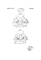
, T'wo embodiments of the invention are illustratedby way of example in the accompanying drawings in which .Fig. 1 shows in end elevation the preferred form of construction. n 1 i Fig.2 isa similar view toFig. 1 showing the second form of construction. h
In the form of construction shown in Fig.
The fish-plates 5 bear against the surfaces They each have two inclined slide surfaces 7 and 8, which form with the surfaces 3 of the rails angles open towards the outer side. The fish-plates 9 engage wedge-like in the open angle of the fish-plates 5 and bear', on
The form of construction shown in Fig. 2 difiers from that which has just been described only in that the fish-plates 5 bear against the web 6 and the lower surfaces 3, the fish-plates 9 however against the upper surfaces 2 of the rails 6.
On the left hand portion of Fig, 2 is shown that the surfaces 11 and 12 extend as in Fig;
1, i. e. perpendicularly to the web 6, so that they move the one towards the other when the nut bolts 10 are being tightened.
On the right hand port-ion of the Fig; 2 is shown that the surfaces 11 and 12 extend parallel to the surfaces 7 and 8 of the fish-plates, so that at the tightening of the nut bolts 10 no approaching takes place; the interval between both surfaces may therefore be kept very small.
The fish- plates 5 and 9 according to both forms of construction may evidently extend over the entire length of the connection on both sides of the rails. It is, however, also possible to subdivide one of the fish-plates at the middle or to provide only "single short sections of the same at the points of the connection through which the nut bolts extend, it being supposed that then the other continuous fish-plate possesses sufiici'ent resistance.
I claim A rail joint connection comprising the combination of a rail having on the lower surface of 'its head and the upper side of its 'foot bearing surfaces extending substantially parallel to the rail base and merging into the web of the rail, with two fish-plates on either side of the rail webQ-the inner one of each pair of fish-plates bearing rigidly against theweb and one of the bearing surfaces of the rail and having slide surfaces of similar inclination in angle open towa d the outer side formed by the slide surfaces and the other supporting surface, whereas the outer fish plate engages like a wedge into said open angle and comes by tightening of the nut bolts into intimate contacton the one hand with said inclined slide surfaces and on the other hand with 'the'other bearing surface of the rail, a vertical and also a horizontal pressing on of all elements ofthe connection at the joint and a vertical, lateral and angular immovability of both fish-plates lbeing obtained by the tightening of the nut olts.
In testimony whereof I aflix my signature.
GUSTAVE YSEBOODT.
Applications Claiming Priority (1)
| Application Number | Priority Date | Filing Date | Title |
|---|---|---|---|
| DE1850163X | 1929-08-21 |
Publications (1)
| Publication Number | Publication Date |
|---|---|
| US1850163A true US1850163A (en) | 1932-03-22 |
Family
ID=7745970
Family Applications (1)
| Application Number | Title | Priority Date | Filing Date |
|---|---|---|---|
| US476581A Expired - Lifetime US1850163A (en) | 1929-08-21 | 1930-08-20 | Rail joint connection |
Country Status (1)
| Country | Link |
|---|---|
| US (1) | US1850163A (en) |
-
1930
- 1930-08-20 US US476581A patent/US1850163A/en not_active Expired - Lifetime
Similar Documents
| Publication | Publication Date | Title |
|---|---|---|
| US1850163A (en) | Rail joint connection | |
| US4448350A (en) | Railroad track stress transfer apparatus | |
| US4940183A (en) | Arrangement for fastening rails | |
| US2419701A (en) | Rail brace | |
| US2147342A (en) | Expansible rail joint | |
| US1186737A (en) | Rail-joint. | |
| US1858759A (en) | Rail joint connection | |
| US1804056A (en) | Rail joint connection | |
| US1227742A (en) | Rail-joint. | |
| US1854361A (en) | Rail joint | |
| US986899A (en) | Rail-joint and rail-fastener. | |
| US1171423A (en) | Rail-joint. | |
| US625676A (en) | hevner | |
| US1429935A (en) | Rail joint | |
| US1182620A (en) | Rail appliance. | |
| US688321A (en) | Railway-frog. | |
| US1005583A (en) | Rail-joint. | |
| US1007724A (en) | Rail connection. | |
| US1215003A (en) | Rail-joint. | |
| US1572368A (en) | Angle bar for railroad rails | |
| US1268464A (en) | Fastening of railway-rails to sleepers. | |
| US1208698A (en) | Rail-joint. | |
| US1775382A (en) | Rail-joint bar | |
| US1355078A (en) | Rail-fastening | |
| US578789A (en) | Railroad-rail joint |