US1850156A - Electric fluid heater - Google Patents
Electric fluid heater Download PDFInfo
- Publication number
- US1850156A US1850156A US353718A US35371829A US1850156A US 1850156 A US1850156 A US 1850156A US 353718 A US353718 A US 353718A US 35371829 A US35371829 A US 35371829A US 1850156 A US1850156 A US 1850156A
- Authority
- US
- United States
- Prior art keywords
- casing
- tubes
- heater
- walls
- heating
- Prior art date
- Legal status (The legal status is an assumption and is not a legal conclusion. Google has not performed a legal analysis and makes no representation as to the accuracy of the status listed.)
- Expired - Lifetime
Links
Images
Classifications
-
- F—MECHANICAL ENGINEERING; LIGHTING; HEATING; WEAPONS; BLASTING
- F24—HEATING; RANGES; VENTILATING
- F24H—FLUID HEATERS, e.g. WATER OR AIR HEATERS, HAVING HEAT-GENERATING MEANS, e.g. HEAT PUMPS, IN GENERAL
- F24H1/00—Water heaters, e.g. boilers, continuous-flow heaters or water-storage heaters
- F24H1/10—Continuous-flow heaters, i.e. heaters in which heat is generated only while the water is flowing, e.g. with direct contact of the water with the heating medium
- F24H1/101—Continuous-flow heaters, i.e. heaters in which heat is generated only while the water is flowing, e.g. with direct contact of the water with the heating medium using electric energy supply
- F24H1/102—Continuous-flow heaters, i.e. heaters in which heat is generated only while the water is flowing, e.g. with direct contact of the water with the heating medium using electric energy supply with resistance
Definitions
- 'i5 a water heater which shall be cheap in construction and efficient in operation, and which inay serve either as a circulation heater toi' a stand boiler or as a semi-instantaneous heater for quickly supplying relatively sinall quantities of hot water.
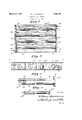
- Figure 2 is an end view thereof, partly in section, and partly in elevation
- Figure 3 is a side elevation of one of the heating elements, parts being' broken away, and one oi the end walls of the casing being shown in section;
- Figure l is a. view partially in side elevation and partially in section of the heating coil itself, and the support tl erefor.
- niy iinproved heater is preferably formed oi sheet inetal and is of relatively shallow rectangular shape.
- lt coinprises a sheet l bent as shown in Figure 2, to torni top,
- bottoni and side walls the top and bottoni walls preferably being ilat, as shown.
- a flanged end plate 2 having flanges 3 welded or otherwise secured to the edges of th-e body portion l. rllhiis, a. completely closed casing or box is formed.
- top and bottoin walls of t-he casing are stayed or tied together and thus prevented from bulging by ineans of partition Serial No. 353,718.
- l In order to heat the liuid in its passage through the casing and around the baille plates 4, l provide a plurality ot heating units, each of which coinprises a tube 6, preterably 'iorined of copper or other good conducting inaterial.
- rEliese tubes are arranged in spaced parallel relation and are interposed between the baille plates 4, asclearly shown in Figure l.
- 'llie tubes entend through openings in the end plates 2 ot the casing and 'Je have their enos rolled over or expanded into these end plates, as indicated at Ga, in the saine inanncr as boiler tubes are set into tube sheets.
- each of the tubes 6 is preferably provided on its upper side with a longitudinal rib or lin 7.
- a longitudinal rib or lin 7. As clearly shown in Figure 2, he tubes 6 are set relatively near the bottoni oi' the casing, but out oi contact therewith, and the hns 7 extend alinost, but not entirely, to the top wall of the casing. rl ⁇ hus, when these tubes are heated, as hereinafter described, there is a tendency tor the liquid adjacent thereto to move or circulate locally and laterally, in planes transverse to the direction of flow,
- the tubes 6 t between the insulating abli arovidel with enlarged ends or heads 8a of a size to snugly it within the tubes.
- l/Vound on this siool is a heatino ⁇ coil 9 of suitable material, and the ends of this coil are brought out through the hollow center of the spool, as clearly shown in Figure e, so that the coils of the several heaters may be properly connected.v As clearly shown in Figure 1, these coils are preferably connected in series, the current entering, say, through the terminal 14 and passing successively through the coils of the several heating units through the end connections 15 and thence out through the terminal 16.
- rhe heating elements comprising the spools 8 and coils 9 are inserted in the interior of the tubes, as clearly shown in Figure 3, the coils having first been embedded and covered with a coating 10 of refractory cement of any suitable character, this cement being applied to the body of the spool until it is flush with the hea-ds 8@ thereof. in other words, the cement lills the space between the body of the spool and the interior of the tube, thus excluding air and thoroughly in sulating the heatine' coil and preventing grounding, should it become broken.
- the ends 2 of the casing are set back a slight distance from the edges of the body portion, so as to form recesses, and these recesses are preferably filled with a heat insulating cement, as indicated at 11. This not only covers and protects the connecting wires 15, but also seals the open ends of the tubes and prevents the access of air thereto.
- VThis pipe 12 is preferably located near the bottom of the casing7 and at one side thereof, and, 'as shown in Figure 1, is extended inwardly for nearly the length of the casing, and provided with a plurality of small discharge holes or openings 12a, so as to distribute the incoming liquid along the length of the first heating unit.
- An electric fluid heater comprising a closed sheet metal casing having flat top, bottom and end walls, a plurality of heating elements extending through said casing and supported by said end walls, and combined stay and battle plates parallel with and interposed between said heating elements and secured to said top and bottom walls.
- An electric iuid heater comprising a closed casing having top, bottom and end walls, a plurality of heating elements extending through said casing and supported by said end walls, armor plates parallel with and interposed between said heating elements, said battle plates being spaced alternately from opposite end walls, inlet and outlet pipes arranged to cause fluid to flow in a zig-zag course around said baffle plates and in contact with said heating elements, and means for creating, adjacent each heating element, a local circulation in planes transverse to the direction ot flow.
- An electric fluid heater comprising a closed casing having llat opposed walls and end walls, a plurality of tubular heating elements extending through said casing and supported by said end walls out of contact with said fiat opposed walls, and combinedstay and baffle plates parallel with and interposed between said heating elements, and secured to said flat opposed walls to tie the same together.
- An electric fluid heater comprising a closed casing adapted to contain the fluid to be heated and having opposite end walls, conducting tubes disposed within said casing, with their open ends extending through and set into said end walls, and insulating tubes having heating coils thereon fitting inside of said conducting tubes, said insulating tubes being of no greater length than said conducting tubes, and having unobstructed open ends.
- An electric fluid heater comprising a closed casing divided into a plurality of compartments, an electric heating element in each compartment, means for causing the fluid to be heated to flow in series through said compartments, and means for causing a local circulation in each compartment in planes transverse to the direction of flow.
- An electric fluid heater comprising a closed casing having flat opposed walls, a plurality of electric heating elements in said casing, inlet'and outlet pipes tapping said casing, and a plurality of parallel baille plates arranged to cause fluid to flow in series past all of said heating elements, the edges of said baffle plates being secured to said hat, opposed walls to brace the latter.
Description
March 22, 1932.
w. RICHARDSON 1,850,156
ELEGTR C FLUD HEATER Filed April 9, 1929 www li0 around,
Patented Mar. 22, 1932 VELLIAIJI RICHARDSON, 0F ATLANTA,
GEORGA, ASSGNOB TO GEORGE STEINGRUBER,
0F HUNTSVLLE, ALABAMA ELECTRIC FLUID HEATER Applicationv Ied April 9, 1929.
'i5 a water heater which shall be cheap in construction and efficient in operation, and which inay serve either as a circulation heater toi' a stand boiler or as a semi-instantaneous heater for quickly supplying relatively sinall quantities of hot water.
In order that the invention inay be readily understood, reference is had to the accompanying drawings, forming part of this specication, and in which Figure l is a sectional plan view of iny iinproved heater;
Figure 2 is an end view thereof, partly in section, and partly in elevation;
Figure 3 is a side elevation of one of the heating elements, parts being' broken away, and one oi the end walls of the casing being shown in section; and
Figure lis a. view partially in side elevation and partially in section of the heating coil itself, and the support tl erefor.
Referring to the drawings in detail, niy iinproved heater is preferably formed oi sheet inetal and is of relatively shallow rectangular shape. lt coinprises a sheet l bent as shown in Figure 2, to torni top,
bottoni and side walls, the top and bottoni walls preferably being ilat, as shown. lnto each end of this body structure is inserted a flanged end plate 2, having flanges 3 welded or otherwise secured to the edges of th-e body portion l. rllhiis, a. completely closed casing or box is formed.
The top and bottoin walls of t-he casing are stayed or tied together and thus prevented from bulging by ineans of partition Serial No. 353,718.
strips l, each preferably of channel shape and provided with flanges 5 welded or otherwise secured to the top and bottoni walls. These partition strins also serve as baille plates to direct the flow of fluid, as hereinafter explained, and to this end, they aie ai'- ranged in parallel relation with their ends alternately spaced from the opposite end walls of the casing so as to provide a Zig-Zag passage.
In order to heat the liuid in its passage through the casing and around the baille plates 4, l provide a plurality ot heating units, each of which coinprises a tube 6, preterably 'iorined of copper or other good conducting inaterial. rEliese tubes are arranged in spaced parallel relation and are interposed between the baille plates 4, asclearly shown in Figure l. 'llie tubes entend through openings in the end plates 2 ot the casing and 'Je have their enos rolled over or expanded into these end plates, as indicated at Ga, in the saine inanncr as boiler tubes are set into tube sheets. Other inethods of securing the tubes, as, for example, by soldering or brazing, can be employed, ii desired. ln order to assist in the circulation of the fluid and also to aid in imparting heat thereto, each of the tubes 6 is preferably provided on its upper side with a longitudinal rib or lin 7. As clearly shown in Figure 2, he tubes 6 are set relatively near the bottoni oi' the casing, but out oi contact therewith, and the hns 7 extend alinost, but not entirely, to the top wall of the casing. rl`hus, when these tubes are heated, as hereinafter described, there is a tendency tor the liquid adjacent thereto to move or circulate locally and laterally, in planes transverse to the direction of flow,
as indicated by the arrows in Figure 2. At
he liquid inay pass between nd he bottoni of the casing, and ffnns and the top oi the casing.
the saine tiine. t the tubes 6 a t between the insulating abli arovidel with enlarged ends or heads 8a of a size to snugly it within the tubes. l/Vound on this siool is a heatino` coil 9 of suitable material, and the ends of this coil are brought out through the hollow center of the spool, as clearly shown in Figure e, so that the coils of the several heaters may be properly connected.v As clearly shown in Figure 1, these coils are preferably connected in series, the current entering, say, through the terminal 14 and passing successively through the coils of the several heating units through the end connections 15 and thence out through the terminal 16.
rhe heating elements comprising the spools 8 and coils 9 are inserted in the interior of the tubes, as clearly shown in Figure 3, the coils having first been embedded and covered with a coating 10 of refractory cement of any suitable character, this cement being applied to the body of the spool until it is flush with the hea-ds 8@ thereof. in other words, the cement lills the space between the body of the spool and the interior of the tube, thus excluding air and thoroughly in sulating the heatine' coil and preventing grounding, should it become broken.
By reference to Figure 1, it will be observed that the ends 2 of the casing are set back a slight distance from the edges of the body portion, so as to form recesses, and these recesses are preferably filled with a heat insulating cement, as indicated at 11. This not only covers and protects the connecting wires 15, but also seals the open ends of the tubes and prevents the access of air thereto.
vLiquid enters the heater through a pipe 12,
adapted to be connected to any suitable source. VThis pipe 12 is preferably located near the bottom of the casing7 and at one side thereof, and, 'as shown in Figure 1, is extended inwardly for nearly the length of the casing, and provided with a plurality of small discharge holes or openings 12a, so as to distribute the incoming liquid along the length of the first heating unit.
he liquid leaves the heater through an outlet pipe 13, and this, as clearly shown in Figure 2, is set at the opposite side of the casing anda-t a point near the top thereof.
From the foregoing, it will be seen that liquid entering the casing through the orifice 12EL of the inlet pipe 12 is delivered against the first heating unit and flows thence around the baflie plates l and along and around the successive heating units until it is finally discharged through the pipe 13. lt is obvious that the liquid in its travel is brought into contact with a very large heating surface and this, combined with the local circu` lation which is set up adjacent the tubes, as hereinbefore described, results in an eX- treinely rapid heating of the liquid. rllhus, a few minutes after currentis turned on, hot water iay be drawn from the pipe 13. Otherwise, the pipes 12 and 13 may be connected to a stand boiler and will heat the same by circulation in the usual manner.
What I claim is 1. An electric fluid heater comprising a closed sheet metal casing having flat top, bottom and end walls, a plurality of heating elements extending through said casing and supported by said end walls, and combined stay and battle plates parallel with and interposed between said heating elements and secured to said top and bottom walls.
2. An electric iuid heater comprising a closed casing having top, bottom and end walls, a plurality of heating elements extending through said casing and supported by said end walls, baie plates parallel with and interposed between said heating elements, said battle plates being spaced alternately from opposite end walls, inlet and outlet pipes arranged to cause fluid to flow in a zig-zag course around said baffle plates and in contact with said heating elements, and means for creating, adjacent each heating element, a local circulation in planes transverse to the direction ot flow.
3. An electric fluid heater comprising a closed casing having llat opposed walls and end walls, a plurality of tubular heating elements extending through said casing and supported by said end walls out of contact with said fiat opposed walls, and combinedstay and baffle plates parallel with and interposed between said heating elements, and secured to said flat opposed walls to tie the same together.
4. An electric fluid heater comprising a closed casing adapted to contain the fluid to be heated and having opposite end walls, conducting tubes disposed within said casing, with their open ends extending through and set into said end walls, and insulating tubes having heating coils thereon fitting inside of said conducting tubes, said insulating tubes being of no greater length than said conducting tubes, and having unobstructed open ends.
5. An electric fluid heater comprising a closed casing divided into a plurality of compartments, an electric heating element in each compartment, means for causing the fluid to be heated to flow in series through said compartments, and means for causing a local circulation in each compartment in planes transverse to the direction of flow.
6. An electric fluid heater comprising a closed casing having flat opposed walls, a plurality of electric heating elements in said casing, inlet'and outlet pipes tapping said casing, and a plurality of parallel baille plates arranged to cause fluid to flow in series past all of said heating elements, the edges of said baffle plates being secured to said hat, opposed walls to brace the latter. 1
ln testimony whereof l affix my signature.
WILLAM RICHARDSON.
Priority Applications (1)
| Application Number | Priority Date | Filing Date | Title |
|---|---|---|---|
| US353718A US1850156A (en) | 1929-04-09 | 1929-04-09 | Electric fluid heater |
Applications Claiming Priority (1)
| Application Number | Priority Date | Filing Date | Title |
|---|---|---|---|
| US353718A US1850156A (en) | 1929-04-09 | 1929-04-09 | Electric fluid heater |
Publications (1)
| Publication Number | Publication Date |
|---|---|
| US1850156A true US1850156A (en) | 1932-03-22 |
Family
ID=23390278
Family Applications (1)
| Application Number | Title | Priority Date | Filing Date |
|---|---|---|---|
| US353718A Expired - Lifetime US1850156A (en) | 1929-04-09 | 1929-04-09 | Electric fluid heater |
Country Status (1)
| Country | Link |
|---|---|
| US (1) | US1850156A (en) |
Cited By (12)
| Publication number | Priority date | Publication date | Assignee | Title |
|---|---|---|---|---|
| US4692592A (en) * | 1984-02-23 | 1987-09-08 | Kale Hemant D | Compartmentalized electric liquid heater |
| US5872891A (en) * | 1996-05-24 | 1999-02-16 | Son; Jae S. | System for providing substantially instantaneous hot water |
| US20090317068A1 (en) * | 2008-06-24 | 2009-12-24 | Wing Yiu Yeung | Water heating apparatus |
| US20100059599A1 (en) * | 2008-09-11 | 2010-03-11 | Ray King | Closed loop heating system |
| US20100092163A1 (en) * | 2008-06-24 | 2010-04-15 | Advanced Materials Enterprises Company Limited | Water Heating Apparatus |
| US20120223065A1 (en) * | 2011-03-04 | 2012-09-06 | Ray King | Electro-thermal heating system |
| US20130037019A1 (en) * | 2010-04-21 | 2013-02-14 | Frederick Johannes Bruwer | Water heater with intermittent energy source |
| US20130315574A1 (en) * | 2011-01-27 | 2013-11-28 | Universite Montpellier 2 Science Et Techniques | Continuous heat treatment method and heating device for an electrically conductive fluid |
| US8855475B2 (en) | 2011-03-04 | 2014-10-07 | Dynacurrent Technologies, Inc. | Radiant heating system and boiler housing for use therein |
| US8933372B2 (en) | 2006-06-29 | 2015-01-13 | Dynacurrent Technologies, Inc. | Engine pre-heater system |
| US9822985B2 (en) | 2012-11-01 | 2017-11-21 | Dynacurrent Technologies, Inc. | Radiant heating system |
| US11536491B2 (en) * | 2020-03-30 | 2022-12-27 | Kurt Schramm | Electric integrated circuit water heater system |
-
1929
- 1929-04-09 US US353718A patent/US1850156A/en not_active Expired - Lifetime
Cited By (17)
| Publication number | Priority date | Publication date | Assignee | Title |
|---|---|---|---|---|
| US4692592A (en) * | 1984-02-23 | 1987-09-08 | Kale Hemant D | Compartmentalized electric liquid heater |
| US5872891A (en) * | 1996-05-24 | 1999-02-16 | Son; Jae S. | System for providing substantially instantaneous hot water |
| US8933372B2 (en) | 2006-06-29 | 2015-01-13 | Dynacurrent Technologies, Inc. | Engine pre-heater system |
| US8463117B2 (en) * | 2008-06-24 | 2013-06-11 | Advanced Materials Enterprises Company Limited | Water heating apparatus |
| US20090317068A1 (en) * | 2008-06-24 | 2009-12-24 | Wing Yiu Yeung | Water heating apparatus |
| US8346069B2 (en) * | 2008-06-24 | 2013-01-01 | Advanced Materials Enterprises Company Limited | Water heating apparatus |
| US20100092163A1 (en) * | 2008-06-24 | 2010-04-15 | Advanced Materials Enterprises Company Limited | Water Heating Apparatus |
| US9429330B2 (en) | 2008-09-11 | 2016-08-30 | Dynacurrent Technologies, Inc. | Closed loop heating system |
| US20100059599A1 (en) * | 2008-09-11 | 2010-03-11 | Ray King | Closed loop heating system |
| US20130037019A1 (en) * | 2010-04-21 | 2013-02-14 | Frederick Johannes Bruwer | Water heater with intermittent energy source |
| US20130315574A1 (en) * | 2011-01-27 | 2013-11-28 | Universite Montpellier 2 Science Et Techniques | Continuous heat treatment method and heating device for an electrically conductive fluid |
| US10082338B2 (en) * | 2011-01-27 | 2018-09-25 | Universite De Montpellier | Continuous heat treatment method for an electrically conductive fluid |
| US8855475B2 (en) | 2011-03-04 | 2014-10-07 | Dynacurrent Technologies, Inc. | Radiant heating system and boiler housing for use therein |
| US9091457B2 (en) * | 2011-03-04 | 2015-07-28 | Dynacurrent Technologies, Inc. | Electro-thermal heating system |
| US20120223065A1 (en) * | 2011-03-04 | 2012-09-06 | Ray King | Electro-thermal heating system |
| US9822985B2 (en) | 2012-11-01 | 2017-11-21 | Dynacurrent Technologies, Inc. | Radiant heating system |
| US11536491B2 (en) * | 2020-03-30 | 2022-12-27 | Kurt Schramm | Electric integrated circuit water heater system |
Similar Documents
| Publication | Publication Date | Title |
|---|---|---|
| US1850156A (en) | Electric fluid heater | |
| US1985830A (en) | Apparatus for treating fluid mediums | |
| US2673919A (en) | Fluid preheater | |
| US1699542A (en) | Radiator | |
| US1880255A (en) | Electric water heater | |
| US1617889A (en) | Electrical water heater | |
| US2175307A (en) | Electric heater | |
| US1696758A (en) | Water heater | |
| US1905439A (en) | Electric fluid heating apparatus | |
| US1920685A (en) | Electric water heater | |
| US1618735A (en) | Water heater | |
| US1446807A (en) | Electric heater for liquids | |
| US1525508A (en) | Electric water heater | |
| US2051930A (en) | Electric heating unit | |
| US2024783A (en) | Electric water heater | |
| US1563562A (en) | Electric heater | |
| US1715378A (en) | Radiator | |
| US1357019A (en) | Electrically-heated water service and system | |
| US624748A (en) | Hot-blast box | |
| US829318A (en) | Electric heater. | |
| US740303A (en) | Apparatus for heating and moistening air. | |
| US2389265A (en) | Recirculation insulated space heater | |
| US846544A (en) | Electric heater. | |
| US2396810A (en) | Water heater | |
| US1420840A (en) | Portable water heater |