US1850133A - Long distance conduit for conveying fluid at high pressure - Google Patents
Long distance conduit for conveying fluid at high pressure Download PDFInfo
- Publication number
- US1850133A US1850133A US554363A US55436331A US1850133A US 1850133 A US1850133 A US 1850133A US 554363 A US554363 A US 554363A US 55436331 A US55436331 A US 55436331A US 1850133 A US1850133 A US 1850133A
- Authority
- US
- United States
- Prior art keywords
- conduit
- fluid
- sections
- high pressure
- long distance
- Prior art date
- Legal status (The legal status is an assumption and is not a legal conclusion. Google has not performed a legal analysis and makes no representation as to the accuracy of the status listed.)
- Expired - Lifetime
Links
Images
Classifications
-
- F—MECHANICAL ENGINEERING; LIGHTING; HEATING; WEAPONS; BLASTING
- F22—STEAM GENERATION
- F22B—METHODS OF STEAM GENERATION; STEAM BOILERS
- F22B37/00—Component parts or details of steam boilers
- F22B37/02—Component parts or details of steam boilers applicable to more than one kind or type of steam boiler
- F22B37/10—Water tubes; Accessories therefor
- F22B37/14—Supply mains, e.g. rising mains, down-comers, in connection with water tubes
-
- Y—GENERAL TAGGING OF NEW TECHNOLOGICAL DEVELOPMENTS; GENERAL TAGGING OF CROSS-SECTIONAL TECHNOLOGIES SPANNING OVER SEVERAL SECTIONS OF THE IPC; TECHNICAL SUBJECTS COVERED BY FORMER USPC CROSS-REFERENCE ART COLLECTIONS [XRACs] AND DIGESTS
- Y10—TECHNICAL SUBJECTS COVERED BY FORMER USPC
- Y10T—TECHNICAL SUBJECTS COVERED BY FORMER US CLASSIFICATION
- Y10T137/00—Fluid handling
- Y10T137/7722—Line condition change responsive valves
- Y10T137/7781—With separate connected fluid reactor surface
- Y10T137/7784—Responsive to change in rate of fluid flow
-
- Y—GENERAL TAGGING OF NEW TECHNOLOGICAL DEVELOPMENTS; GENERAL TAGGING OF CROSS-SECTIONAL TECHNOLOGIES SPANNING OVER SEVERAL SECTIONS OF THE IPC; TECHNICAL SUBJECTS COVERED BY FORMER USPC CROSS-REFERENCE ART COLLECTIONS [XRACs] AND DIGESTS
- Y10—TECHNICAL SUBJECTS COVERED BY FORMER USPC
- Y10T—TECHNICAL SUBJECTS COVERED BY FORMER US CLASSIFICATION
- Y10T137/00—Fluid handling
- Y10T137/7722—Line condition change responsive valves
- Y10T137/7781—With separate connected fluid reactor surface
- Y10T137/7793—With opening bias [e.g., pressure regulator]
- Y10T137/7805—Through external pipe
-
- Y—GENERAL TAGGING OF NEW TECHNOLOGICAL DEVELOPMENTS; GENERAL TAGGING OF CROSS-SECTIONAL TECHNOLOGIES SPANNING OVER SEVERAL SECTIONS OF THE IPC; TECHNICAL SUBJECTS COVERED BY FORMER USPC CROSS-REFERENCE ART COLLECTIONS [XRACs] AND DIGESTS
- Y10—TECHNICAL SUBJECTS COVERED BY FORMER USPC
- Y10T—TECHNICAL SUBJECTS COVERED BY FORMER US CLASSIFICATION
- Y10T137/00—Fluid handling
- Y10T137/8593—Systems
- Y10T137/87917—Flow path with serial valves and/or closures
Definitions
- Atnorma1bretsmal1 "loads” the reducin g":fvalvejsfakev fdpelfaljedaby largest; qu ant ity efsteam vflows .threughfthe V I pipe,"theivalve eontyolling 'meene 8+1 0 lmey” y be operated ini'response tbvthe rate of flow o'f fidid through the pipe 01'" cdridui't so thflt s they closethe valves in-respons e;t o the-[dcrase ".dei'nend fo l steam, 01' like fluid, Owing to the pygvisien of ⁇ the reducing valves it, is
- valves and 20 represent the end portions of two success ve conduit sections.
- 1 21 1s a valvecas-' ing for-connecting the sections in series.
- the valve member 22 1s regulated by a pressure responsive device 23 including a diaphragm 241:0 which 'niember 22 is fastened.
- f For moving valve member 22 in responseh'tofthe flow of fluidI may provide one conduitwith a restriction, in the p'resent instance, ind1cated at 25, Withrespe'ctto conduit 'section20 and connectthe upper andlower half of cas ing23 by means of pipes 26jand2'T respectively with the two sides ofthe restriction.
- Flow responsive devices of this kind are well known in the art. In the present instance the arrangement operates to cause opening of the Valve if the demand for fluid and accordingly the flow of fluid through the conduit increases and closing of the valve if the flow decreases. 5 V
- a long distance conduit for conveying fluid athigh pressure comprising sections of,
- a long distance conduit for conveying fluid at high pressure comprising sections of difierent strength, pressure, reducing valves arranged between said sections and means for controlling said valves. 7 r
- a long distance conduit for conveying fluid at high pressure comprising sections of different strength, pressure reducing valves rarrangledbetween said sections, and means .icallyjoperative,means for controlling said valves ⁇ 1n such manner'that the pressures in said sections at partial loads cannot exceed the values occurring at fullload.
- a conduit of relatively considerable length for conveying fluid to the consumer said conduit beingdivided into a plurality of sections of decreasingjstrength as regards the direction of'flow, valvemeans provided be tween consecutive sections, and Ine'ans for regulatlngthe valve means, interins or fluid conditions.
- a conduit ofrelatively considerablelength for conveying fluid to the consumer, said conduit beingdivided into a plurality of sections of decreasing; strength as regards the direction of flow, valve-means provided be tween consecutive sections, and pressure responsive devices" for regulating the valve means :in order to maintain substantially constant the fluid pressure at the inlet of each section.
- conduit for conveying fluid at high pressure comprising a first sec tion through .Whichthe fluid enters and a second section of less'strength than the first section to which the fluid is conveyed from the first section, and means-for regulating the flow of fluid fromthe first section to the sec- .ond section for preventing the pressure in the second section from increasing. at partial load beyond the pressure existing in the sec ondsection atfull load j V 'In testimony whereof I aflix my signature.
Description
March 22, 1932;
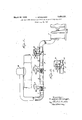
F. MUNZlNGER LON G DISTANCE CONDUIT FOR CONVEYING FLUID AT HIGH PRESSURE Filed July 31, 1931 hivehtor a Friedrich Milmzinger, b9
His Attorneg Patentedmar.22,1932}- m wfi m s mew; GEBMANY; s
V instance in plants "designedytef-fed eleetric. power to a thickly OPii l'fitedgdi itI- ie t having 7 high peak l'0; 1d's ',jas in jjlzi rge" cities; it is ad visible t'd locate thfe boiler plant in anyoutefrr dietfiet iiiiditd 's ilpply live steafii'thmughlong 0 mined o t e specification :an'
i vdia ;mm11-111mmany by my Qgexamp1q airt1y $51 191kildme i we}; manner that the, pressures "in the 'see- -siderab1yreduced. e r I I 11 lthe; *p-pesentinstance -la e e the succeeding sec-1510111 as regards; .the du ec- 1 a mQdijfica oiled and T 1 I a turbo-generatorwhich a'reeennected with 1 eachfother by a long distance pipe'P. CThis :pipeis" subdivided into consecutivee sections ,1, 2; 410 1? diffefelltffeistiviw to innel fpres sure; For instanc'efsectibp Ima'ybedesig ned as threat-1e" mlyee arrangedibetive mhe g 'c Controlling means ofmwell'iknowrikirid whi cfhf on-1 1% zitins. iin ectipne, iinisectien s :2 10
LO-game,respee ve Atnorma1bretsmal1 "loads" the reducin g":fvalvejsfakev fdpelfaljedaby largest; qu ant ity efsteam vflows .threughfthe V I pipe,"theivalve eontyolling 'meene 8+1 0 lmey" y be operated ini'response tbvthe rate of flow o'f fidid through the pipe 01'" cdridui't so thflt s they closethe valves in-respons e;t o the-[dcrase ".dei'nend fo l steam, 01' like fluid, Owing to the pygvisien of {the reducing valves it, is
e h 'eh vi tl r reducin valves 5, 6 wel -7. 'bemgyggulalged;
10f pressureexlstmg imthe ;1 n1et fe are forced in an opening direction by the arrangement of a spring 17 between the diaphragm and the lower casing half. The'upper half of the casings is connected by means of conduits 8, 9 and 10 to the inlet of thesucceeding conduit sections as regards the direction of the flow of fluid. 7 i y r The operation of this arrangement is as follows: Let us assume that the consumer T operates under maximum load. If, now the; demand of flu1d, such as elastic fluid, .decreases, owing for lnstance to a decreased load of the turbo-generator, it will cause a building-up of pressure in. the conduit. This efiects an increase of pressure in the upper casinghalves of the fluidresponsive devices, resulting in a closing movementof the movable valve members whereby the original pressure is maintained substantially. constant. It will be readily seen that anopen ing movement of the valves takes place. ifthe demand 'for elastic fluid increases. f
p In Fig. 2 I have shown a modification according to my inventionfor regulating the pressure reducing means in terms of flow of elastic fluid'through the conduit,ithat is,
response to the demand forelasticfluid... 19
and 20 represent the end portions of two success ve conduit sections. 1 21 1s a valvecas-' ing for-connecting the sections in series. The valve member 22 1s regulated by a pressure responsive device 23 including a diaphragm 241:0 which 'niember 22 is fastened. f For moving valve member 22 in responseh'tofthe flow of fluidI may provide one conduitwith a restriction, in the p'resent instance, ind1cated at 25, Withrespe'ctto conduit 'section20 and connectthe upper andlower half of cas ing23 by means of pipes 26jand2'T respectively with the two sides ofthe restriction. Flow responsive devices of this kind are well known in the art. In the present instance the arrangement operates to cause opening of the Valve if the demand for fluid and accordingly the flow of fluid through the conduit increases and closing of the valve if the flow decreases. 5 V
Instead of subdividing the pipe into four sections as described above, it'may be subdivided into a greater or lesser number of sections, as the case may be. r p
' I wish it'to be understood that. I do not desire to be limited to thefaxac-t details of construction shown and described, for obvious modifications will occur to a} person skilled in the art.
. In the claims aflixed to this specificationno selection of any particular modification ofthe invention is intended to the exclusion of other modifications thereof and the right to subsequentlymake claim to any modification not covered by these claims is expressly reserved.
IclaimF- 1. A long distance conduit for conveying fluid athigh pressure comprising sections of,
different strength and pressure reducing valves arranged between said sections.
2. A long distance conduit for conveying fluid at high pressure comprising sections of difierent strength, pressure, reducing valves arranged between said sections and means for controlling said valves. 7 r
3. A long distance conduit for conveying fluid at high pressure comprising sections of different strength, pressure reducing valves rarrangledbetween said sections, and means .icallyjoperative,means for controlling said valves{ 1n such manner'that the pressures in said sections at partial loads cannot exceed the values occurring at fullload.
6. In combination with a -fluid consumer, a conduit of relatively considerable length for conveying fluid to the consumer, said conduit beingdivided into a plurality of sections of decreasingjstrength as regards the direction of'flow, valvemeans provided be tween consecutive sections, and Ine'ans for regulatlngthe valve means, interins or fluid conditions.
7. In combination with a fluid consumer, a conduit ofrelatively considerablelength for conveying fluid to the consumer, said conduit beingdivided into a plurality of sections of decreasing; strength as regards the direction of flow, valve-means provided be tween consecutive sections, and pressure responsive devices" for regulating the valve means :in order to maintain substantially constant the fluid pressure at the inlet of each section.
,8. Along distance conduit for conveying fluid at high pressure comprising a first sec tion through .Whichthe fluid enters and a second section of less'strength than the first section to which the fluid is conveyed from the first section, and means-for regulating the flow of fluid fromthe first section to the sec- .ond section for preventing the pressure in the second section from increasing. at partial load beyond the pressure existing in the sec ondsection atfull load j V 'In testimony whereof I aflix my signature.
' FRIEDRICH MUNZINGER.
Applications Claiming Priority (1)
| Application Number | Priority Date | Filing Date | Title |
|---|---|---|---|
| DE1850133X | 1930-06-10 |
Publications (1)
| Publication Number | Publication Date |
|---|---|
| US1850133A true US1850133A (en) | 1932-03-22 |
Family
ID=7745964
Family Applications (1)
| Application Number | Title | Priority Date | Filing Date |
|---|---|---|---|
| US554363A Expired - Lifetime US1850133A (en) | 1930-06-10 | 1931-07-31 | Long distance conduit for conveying fluid at high pressure |
Country Status (1)
| Country | Link |
|---|---|
| US (1) | US1850133A (en) |
Cited By (7)
| Publication number | Priority date | Publication date | Assignee | Title |
|---|---|---|---|---|
| US2524540A (en) * | 1943-08-12 | 1950-10-03 | Towler & Son Ltd | Control system for regulating the rate of flow of liquids or other materials capable of flowing |
| US2697940A (en) * | 1947-10-28 | 1954-12-28 | Bendix Aviat Corp | Control for air boxes |
| US2703013A (en) * | 1949-04-18 | 1955-03-01 | William A Wildhack | Pneumatic control and metering system |
| US2886048A (en) * | 1955-01-20 | 1959-05-12 | Bendix Aviat Corp | Pneumatic turbine drive control system |
| US3040522A (en) * | 1958-09-12 | 1962-06-26 | Bendix Corp | Rocket engine control system |
| US3043362A (en) * | 1958-05-26 | 1962-07-10 | Applic Et De Const Pour Materi | Apparatus for machining a piece of work by means of an erosive fluid |
| US20100186840A1 (en) * | 2008-12-16 | 2010-07-29 | Kartalov Emil P | Multi-valve microfluidic devices and methods |
-
1931
- 1931-07-31 US US554363A patent/US1850133A/en not_active Expired - Lifetime
Cited By (8)
| Publication number | Priority date | Publication date | Assignee | Title |
|---|---|---|---|---|
| US2524540A (en) * | 1943-08-12 | 1950-10-03 | Towler & Son Ltd | Control system for regulating the rate of flow of liquids or other materials capable of flowing |
| US2697940A (en) * | 1947-10-28 | 1954-12-28 | Bendix Aviat Corp | Control for air boxes |
| US2703013A (en) * | 1949-04-18 | 1955-03-01 | William A Wildhack | Pneumatic control and metering system |
| US2886048A (en) * | 1955-01-20 | 1959-05-12 | Bendix Aviat Corp | Pneumatic turbine drive control system |
| US3043362A (en) * | 1958-05-26 | 1962-07-10 | Applic Et De Const Pour Materi | Apparatus for machining a piece of work by means of an erosive fluid |
| US3040522A (en) * | 1958-09-12 | 1962-06-26 | Bendix Corp | Rocket engine control system |
| US20100186840A1 (en) * | 2008-12-16 | 2010-07-29 | Kartalov Emil P | Multi-valve microfluidic devices and methods |
| US8424560B2 (en) * | 2008-12-16 | 2013-04-23 | University Of Southern California | Multi-valve microfluidic devices and methods |
Similar Documents
| Publication | Publication Date | Title |
|---|---|---|
| US1850133A (en) | Long distance conduit for conveying fluid at high pressure | |
| US2865397A (en) | Hydraulic governor | |
| US1645601A (en) | Velocity-reducing valve | |
| US2586871A (en) | Composite pressure seal | |
| US2042462A (en) | Fluid flow control device | |
| US2074690A (en) | Steam trap | |
| US2018372A (en) | Labyrinth packing device | |
| US2385537A (en) | Valve operating mechanism | |
| US1673041A (en) | Rate of flow controller | |
| US1715665A (en) | Valve for steam or other fluids and liquids | |
| US2920867A (en) | Reheat turbine apparatus | |
| US2169810A (en) | Lubricated valve | |
| US1838740A (en) | Fluid pressure conduit | |
| US2008722A (en) | Pressure regulating and reducing device | |
| GB751090A (en) | Improvements in or relating to pipelines | |
| US2009423A (en) | Two-stage packing with equalizer connection | |
| US1465172A (en) | Lubricating system | |
| US3516443A (en) | Pilot operated valve | |
| US2247302A (en) | Hydraulic remote control device | |
| US2763291A (en) | Shock wave absorber | |
| US130835A (en) | Improvement in water-pressure check-valves | |
| US1111312A (en) | Self-balancing device for turbines. | |
| DE663060C (en) | Device for comparing the flow velocity in pipelines | |
| US1539747A (en) | Valve for water systems | |
| US314007A (en) | Steam-valve connection for railway-cars |