US1850105A - Electrical condenser - Google Patents
Electrical condenser Download PDFInfo
- Publication number
- US1850105A US1850105A US358838A US35883829A US1850105A US 1850105 A US1850105 A US 1850105A US 358838 A US358838 A US 358838A US 35883829 A US35883829 A US 35883829A US 1850105 A US1850105 A US 1850105A
- Authority
- US
- United States
- Prior art keywords
- condenser
- container
- condensers
- terminal
- unit
- Prior art date
- Legal status (The legal status is an assumption and is not a legal conclusion. Google has not performed a legal analysis and makes no representation as to the accuracy of the status listed.)
- Expired - Lifetime
Links
Images
Classifications
-
- H—ELECTRICITY
- H01—ELECTRIC ELEMENTS
- H01G—CAPACITORS; CAPACITORS, RECTIFIERS, DETECTORS, SWITCHING DEVICES OR LIGHT-SENSITIVE DEVICES, OF THE ELECTROLYTIC TYPE
- H01G2/00—Details of capacitors not covered by a single one of groups H01G4/00-H01G11/00
- H01G2/02—Mountings
- H01G2/04—Mountings specially adapted for mounting on a chassis
Definitions
- My invention relates to electrical condensers, and more particularly to condensers having a fixed comparatively high capacitance for use in radio receiving apparatus.
- condenser structure as of the multi-unit type, is compressed within the walls of a container, or sub-container, by a hearing or pressure plate upon which the compressive force is 30 exerted; more particularly upper edges or portions of the container or sub-container are bent over and clamped into engagement -with corresponding edges of the bearing plate to maintain the same and the condenser structure in their finally. compressed positions; and more particularly the lead conductors from the condenser structure are individually brought out to a unit comprising a sealing closure member for the condenser structure, said lead conductors. extending through and sealed as by soldering to said closure member.
- a lead conductor extends through a sealing and insulating terminal unit comprising a cap member or the like of insulating material having molded therein an annularmetallic flange member or skirt and a hollow terminal or prong, through which the lead conductor extends; more particularly the metallic flange member or skirt is secured and sealed at its outer periphery, as by solderin or welding, to a metallic container or wa 1 within which apparatus connected to said conductor is disposed; and more particularly the aforesaid lead conductor extending through said insulating member and hollow prong is secured and sealed within the same by a conducting material, as solder, effectively sealing the terminal and electrically connecting said conductor to said prong.
- electrical apparatus as condenser structure or the like, which is to be electrically sealed within a container, is provided with lead conductors of suitable length permitting (the same to be mechanically and electrically connected, as by soldering or welding, to the terminals of an insu- 1929. Serial No. 858,838.
- lating closure unit and more particularly, a cover or closure member having an aperture thereln, is sealed, as by soldering or welding, to the container within which apparatus to be sealed is disposed, and the aforesaid insulating closure unit is likewise sealed within said aperture to the cover member to permanently and effectually seal the interior of the container from the atmosphere.
- My invention further resides in method and apparatus of the character hereinafter described and-claimed.
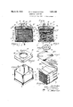
- Fig. 1 is an elevational cross-sectional view of a condenser unit.
- Fig. 2 is an elevational cross-sectional view taken along the line 2-2 of Fig. 1.
- Fig. 3 is a perspective View of condenser structure removed from its container.
- Fig. 4 illustrates a bearing plate for condenser structure
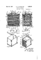
- Fig. 5 is a perspective view of a container within which condenser structure is disposed.
- Fig. 6 is a perspective view of a cover or closure member.
- Fig. 7 illustrates an insulating terminal unit.
- Fig. 8 is an elevational cross-sectional-view of another form of my invention.
- Fig. 9 is an elevational cross-sectional view taken along the line 99 of Fig. 8.
- Fig. 10 is a perspective view of condenser structure removed from its container.
- Fig. 11 illustrates a container within which condenser structure shown in Fig. 10 may be dis osed.
- ig. 12 is a cover member for the container in Fig. 11.
- Fig. 1.3 is an insulating terminal unit.
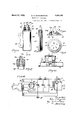
- Fig. 14 is a diagrammatic illustration of circuit connections for a plurality of condense-rs grouped. together in the same unit and used inradio receiving apparatus. 1
- Fig. 15 is a cross-sectional view of another form of my invention.
- Fig. 16 is a cross-sectional view taken along the line 15-15 of Fig. 14.
- Fig. 17 is a cross-sectional view of a modified form of terminal unit.
- Figs. 18' and 19 are views of an insulating terminal unit.
- I Fig. 20 is a fragmentary view of mounting structure.
- a container 1 of suitable material such as tinned sheet metal, for example, comprises a rec:
- tangular structure having a ribbed bottom structure 2 for the purpose of increasing the strength thereof.
- the bottom 2 is secured and sealed as by soldering, to the wall structure of container 1 and is further reinforced by a flat plate 3.
- Opposing edges of the up per wall structure are cut away or slotted as at 4 for a purpose hereinafter described, the
- the external plate orfoil of condensers C, C and C are at the same or ground potential (Fig. 14), ground connection 8 extending alongone side of the condenser structure to afford a common ground connection at 9 to the said condensers.
- a bearing plate 15 comprising oppositely upturned edges or flanges-15a is disposed between the members 11, and 11a, which comprises an extension thereof. Pressure is brought to bear upon plate 15 and the rolled condensers 6 arecompressed downwardly within container 1 to a desired extent, after which those portions of the upper walls of the container between slots 4 are bent inwardl and over the flanges 15a of the bearing plate Fig. 2) to clamp and maintain the same in its compressed position.
- a cover or closure member 16 comprises a flanged-aperture 17 :entrally thereof and a pair of smaller apertures 18 and 19 for a purpose hereinafter described.
- An insulating terminal unit '20 adapted to be disposed in registering relation with respect to aperture 17 comprises a plug or cap 21 of insulating material adapted to be molded into different shapes, and a metallic annular flange or skirt 22 molded to member 21.
- cap 21 has molded therein a plurality of hollow conductors or terminal prongs 23 closed at their lower ends 24 to prevent the passages 23a 'ent that wrapper 12 protects and serves to within the terminals from fillin with the insulating material during the mol ding process.
- the lower ends of the terminal prongs are grooved at 23b to permit the ins'ulatingmaterial to firmly grip the same. Beneath and in registering relation with each terminal prong is molded a recess 25. After the molding process has been completed, a continuous passageis drilled from recess 25 through theinsulating material and closed ends of the terminals ,to permit a conductor to be-led through and connected to the terminal unit in a manner hereinafter described.
- Figs. 1 and 2 there is shown a terminal prong in cross-section and a lead conductor 10 extending therethrough and sealed within the hollow passage of .the terminal by a conducting material '26 such as solder, for
- the terminal unit 20 Since during the assembly of the condenser unit, the terminal unit 20 is secured in sealed relation to cover 16 at 27 as by soldering, cover 16 likewise being soldered and sealed to the container 1 at 28, it will be apparent that sealing the leadconductors 10 through their respective terminals completes, except for apertures 18 and 19, hermetic sealing of the condenser structure within the contamer.
- the upper ends of the terminals are preferably notched at 230, so thatthe loose lead conductors extending through the termina'ls may be bent overthe notches and clipped ofi prior to the soldering process.
- the ends of the terminal prongs havin the conductors therein are dipped into i so der or the like, which partially fills thepassages 23a to effectively seal the conductor within terminal 23 and forms an external bead to electrically and permanently connect the'corresponding conductor thereto.
- the common ground conductor 8 which extends through aperture 19 in the cover membar is sealed and electrically connected thereto by solder or the like.
- the condenser unit is subsequently subjected to heat and all air is evacuated therefrom through aperture 18, after which an insulating compound W of suitable characteristics is forced in a hot liquid state under pressure through aperture 18 to impregnate the condenser structure in a manner well known in the art.
- the aperture 18 is sealed with solder or the like after the condenser has been impregnated.
- Figs. 8 to '13 inclusive is illustrated a condenser unit larger and more rugged in construction than that previously described.
- the individual rolled condensers 6, 6a, etc., (Fig. 10) are compressed between plates 30 and 31, and are held in such position'by a metallic strip or subcontainer. 32 of suitable material, as tinned sheet metal. Extending underneath plate 31, and alon opposite sidesof the rolled condensers, t e'upper edges of the sub-container 32 are bent over as at 32a to engage l to 7 inclusive,
- the walls of the main container 34 do not need to be of such heavy material as would be necessaryto maintain the rolled condensers in their compressed position.
- the condenser structure after it has been inserted within its container, is connected through its lead conductors 35 to a terminal unit 20. Since the remaining details of construction and assembly are similar to those described with reference to Figs.
- the condenser structure may be suitably compressed independently of its main container and held in-such position by 'a subcontainer or equivalent which forms with the rolled condensers a unitadapted to be readily inserted Within the main container.
- the connections are soldered to the respective condenser terminals of the 'unit after compression of the same and before insertion within the container.
- the conducting terminal strips t of the condensers which are usually disposed loosely within the condenser rolls, are firmly clamped in position by the compressed rolls and 'so tend to remain in normal position during and after the soldering operation.
- the skirt 22 molded to the insulating cap may comprise the entire cover section, erably it is of smaller size due to greater convenience in sealing the conductors Within the terminals.
- FIG. 14 an electrical network, specifically an incomplete circuit diagram of a power filter system for radio receiving apparatus, wherein a source of alternating current S is connected to the primary of a transformer T to supply power to the circuits in question.
- the secondary windings of transformer T supply current to the respective filaments of a rectifier'tube R and a power tube V, as well as current to a filter circuit whose terminals are connected to the double anode a and a1, and the filament f of the rectifier tube.
- the filter circuit comprises inductances L and L1 connected in series, and condensers C, C and C connected in shunt therewith 'in the usual manner.
- Each of the condensers C, G and C have corresponding terminals connected to a common ground at E and are housed within a v Referring to Figs; and 16, there is illustrated a single condenser of smaller capacity suitable for use,for example, as the series -co denser C Fig. 14, comprisin a casing g 40 aving a condenser 41 of any suitable type disposed therein, and a bearing late 42 formopposite end thereof.
- the sleeve-like mem- Q'dber's 46 are disposed within registering aperl-tures in one wall of the container 40 and are secured thereto at their peripheries 47 by solder'or the like.
- Conductors 48 extending through the terminal'prongs are sealed and Q3 electrlcally connected thereto in the manner previously described, and the condenser may subsequently bevimpregnated with an' insulating compound in any well knbwn manner.
- FIG. 20 there is shown mounting strucas ture for a condenser 'unit of the type previously described.
- the main container l-is mount ed in inverted position upon a sub-base or panelb, to which it is secured in any suitable -manner as bybolts, rivets, etc.
- the insulat- 35 ing terminal cap 21 extends through an aperture in panel b, he terminals 23 thereof being connectedto lead conductors a which are connected to other a paratus.
- a main base B comprising part 0 a housing (not shown) '5 is disposed beneath and spaced from panel I), 1
- a condenser unit comprising a plurality of rolled condensers, a sheet-metal container therefor, a bearing plate exertingpressure on said condensers, means comprising folded portions of said sheet-metal container engaging said bearing plate to hold it in position 50 maintaining said condensers under compres- .sion, and a closure member se'alingSaid-com tainer independently of said bearing-plate.
- a condenser unit comprising a plurality f of rolled condensers, a container therefor, a -bearing plate having upwardl extending I flanges exerting pressure on sai condensers,
- a condenser umt comprising a plurality of rolled condensers, a container therefor,
- a condenser unit comprising a container, a sheet-metal structure disposed within said container and having walls embracing a rolled condenser, a bearing plate for exertmg pressureon said condenser, and means comprlsing upper wall portions of said structure for engagmg said bearing plate to maintain said condensers in compressed position independently of said container.
Description
March'22, 1932. w, HIGGINBOTTOM 1,850,105
ELECTRICAL ONDENSEk Filed April 29, 1929 5 Sheetg-Sheet l Malrch zz, 1932. w, HIGGINBOTTQM 1,850,105
ELECTRICAL CONDENSER Filed April 29, 1929 3 Sheets-Sheet 2 March 22, 1932.
w. E. HIGGINBOTTQM ELECTRICAL CONDENSER Filed April 29, 1929 .5 sheets-Sheet 5 Fi /$5 All/71101111111 L .7 r 2 Patented Mar. 22, 1932 UNITED STATES PATENT OFFICE WILLIAM E. HIGGINBOTTOM, F PHILADELPHIA, PENNSYLVANIA, ASSIGNOR TO AT- WATER KENT MANUFACTURING COMPANY, OF PHILADELPHIA, PENNSYLVANIA, A
CORPORATION OF PENNSYLVANIA ELEc'rRicAL CONDENSER Application file d ,April 29,
My invention relates to electrical condensers, and more particularly to condensers having a fixed comparatively high capacitance for use in radio receiving apparatus.
In accordance with my invention, condenser structure, as of the multi-unit type, is compressed within the walls of a container, or sub-container, by a hearing or pressure plate upon which the compressive force is 30 exerted; more particularly upper edges or portions of the container or sub-container are bent over and clamped into engagement -with corresponding edges of the bearing plate to maintain the same and the condenser structure in their finally. compressed positions; and more particularly the lead conductors from the condenser structure are individually brought out to a unit comprising a sealing closure member for the condenser structure, said lead conductors. extending through and sealed as by soldering to said closure member.
Further in accordance with my invention, a lead conductor extends through a sealing and insulating terminal unit comprising a cap member or the like of insulating material having molded therein an annularmetallic flange member or skirt and a hollow terminal or prong, through which the lead conductor extends; more particularly the metallic flange member or skirt is secured and sealed at its outer periphery, as by solderin or welding, to a metallic container or wa 1 within which apparatus connected to said conductor is disposed; and more particularly the aforesaid lead conductor extending through said insulating member and hollow prong is secured and sealed within the same by a conducting material, as solder, effectively sealing the terminal and electrically connecting said conductor to said prong.
Further and more specifically in accordance with my invention, electrical apparatus as condenser structure or the like, which is to be electrically sealed within a container, is provided with lead conductors of suitable length permitting (the same to be mechanically and electrically connected, as by soldering or welding, to the terminals of an insu- 1929. Serial No. 858,838.
lating closure unit; and more particularly, a cover or closure member having an aperture thereln, is sealed, as by soldering or welding, to the container within which apparatus to be sealed is disposed, and the aforesaid insulating closure unit is likewise sealed within said aperture to the cover member to permanently and effectually seal the interior of the container from the atmosphere.
My invention further resides in method and apparatus of the character hereinafter described and-claimed.
Electrical apparatus, such as condensers or the like, which of necessity have to be hermetically sealed with respect to the atmosphere to avoid deterioration and ultimate breakdown due to small amounts of moisture coming in contact therewith, have heretofore presented difiiculties in sealing due to the fact that lead conductors, or members electrically connected thereto, from the apparatus .must extend in both sealing and insulating relation through the walls of the structure enclosing said apparatus. In condenser structure particularly, it is essential that the seal be both effective and permanent, since admission of air containing only small amounts of moisture will eventually cause failure of the condenser. Mechanical clam ing means which are relied upon to seal tide closure members or apertures through which the lead conductors extend have the disadvantage that they are not integrally formed so as to absolutely prevent air leakage in case of relative deformation, due to temperature changes or for other reasons, between the clamping members.
By my invention, it is possible to permanently and effectively seal the conductor through the wall of the container and at the same time to electrically insulate it with respect thereto. To this nd, the lead conductor the forms-my invention may take, reference is had to the accompanying drawings in which:
Fig. 1 is an elevational cross-sectional view of a condenser unit.
Fig. 2 is an elevational cross-sectional view taken along the line 2-2 of Fig. 1.
Fig. 3 is a perspective View of condenser structure removed from its container.
Fig. 4 illustrates a bearing plate for condenser structure;
Fig. 5 is a perspective view of a container within which condenser structure is disposed.
Fig. 6 is a perspective view of a cover or closure member.
Fig. 7 illustrates an insulating terminal unit.
Fig. 8 is an elevational cross-sectional-view of another form of my invention.
' Fig. 9 is an elevational cross-sectional view taken along the line 99 of Fig. 8.
Fig. 10 is a perspective view of condenser structure removed from its container.
Fig. 11 illustrates a container within which condenser structure shown in Fig. 10 may be dis osed.
ig. 12 is a cover member for the container in Fig. 11.
Fig. 1.3 is an insulating terminal unit.
Fig. 14 is a diagrammatic illustration of circuit connections for a plurality of condense-rs grouped. together in the same unit and used inradio receiving apparatus. 1
Fig. 15 is a cross-sectional view of another form of my invention.
Fig. 16 is a cross-sectional view taken along the line 15-15 of Fig. 14.
Fig. 17 is a cross-sectional view of a modified form of terminal unit.
Figs. 18' and 19 are views of an insulating terminal unit. I Fig. 20 is a fragmentary view of mounting structure. v
Referring to Figs. 1 to 7 inclusive, a container 1 of suitable material, such as tinned sheet metal, for example, comprises a rec:
tangular structure having a ribbed bottom structure 2 for the purpose of increasing the strength thereof. The bottom 2 is secured and sealed as by soldering, to the wall structure of container 1 and is further reinforced by a flat plate 3. Opposing edges of the up per wall structure are cut away or slotted as at 4 for a purpose hereinafter described, the
' sulating and conducting materials wound in the form of a roll, are stacked one above the other and temporarily held together by a I band 7 of paper or thelike. In the present instance, the external plate orfoil of condensers C, C and C are at the same or ground potential (Fig. 14), ground connection 8 extending alongone side of the condenser structure to afford a common ground connection at 9 to the said condensers. The
opposite terminals of the condenser, which are to be connected to apparatus exteriorly of the condenser unit are connected to lead conductors 10 which extend upwardly along" the opposite sides of the condensers. By this arrangement, capacity coupling between the circuits comprising the individual condensers is substantially prevented. 'A member 11 of light but stron cardboard is secured by band 7 to the top 0% the condenser-structure and serves to separate the lead conductors 10 from insulate conductors 10 from the adjacent me-. tallic wall structure of the container, and in addition serves to maintain the lead conductors in their proper relation so that they may be readily connected to terminal structure hereinafter described.
With the condenser structure within con- .tainerl, a bearing plate 15 comprising oppositely upturned edges or flanges-15a is disposed between the members 11, and 11a, which comprises an extension thereof. Pressure is brought to bear upon plate 15 and the rolled condensers 6 arecompressed downwardly within container 1 to a desired extent, after which those portions of the upper walls of the container between slots 4 are bent inwardl and over the flanges 15a of the bearing plate Fig. 2) to clamp and maintain the same in its compressed position.
A cover or closure member 16 comprises a flanged-aperture 17 :entrally thereof and a pair of smaller apertures 18 and 19 for a purpose hereinafter described. An insulating terminal unit '20 adapted to be disposed in registering relation with respect to aperture 17 comprises a plug or cap 21 of insulating material adapted to be molded into different shapes, and a metallic annular flange or skirt 22 molded to member 21. Referring more particularly to Figs. 18 and 19, cap 21 has molded therein a plurality of hollow conductors or terminal prongs 23 closed at their lower ends 24 to prevent the passages 23a 'ent that wrapper 12 protects and serves to within the terminals from fillin with the insulating material during the mol ding process. The lower ends of the terminal prongs are grooved at 23b to permit the ins'ulatingmaterial to firmly grip the same. Beneath and in registering relation with each terminal prong is molded a recess 25. After the molding process has been completed, a continuous passageis drilled from recess 25 through theinsulating material and closed ends of the terminals ,to permit a conductor to be-led through and connected to the terminal unit in a manner hereinafter described.
' In Figs. 1 and 2 there is shown a terminal prong in cross-section and a lead conductor 10 extending therethrough and sealed within the hollow passage of .the terminal by a conducting material '26 such as solder, for
example. Since during the assembly of the condenser unit, the terminal unit 20 is secured in sealed relation to cover 16 at 27 as by soldering, cover 16 likewise being soldered and sealed to the container 1 at 28, it will be apparent that sealing the leadconductors 10 through their respective terminals completes, except for apertures 18 and 19, hermetic sealing of the condenser structure within the contamer. The upper ends of the terminals are preferably notched at 230, so thatthe loose lead conductors extending through the termina'ls may be bent overthe notches and clipped ofi prior to the soldering process. In practice, the ends of the terminal prongs havin the conductors therein are dipped into i so der or the like, which partially fills thepassages 23a to effectively seal the conductor within terminal 23 and forms an external bead to electrically and permanently connect the'corresponding conductor thereto. With the parts in their'above described positions, the common ground conductor 8 which extends through aperture 19 in the cover membar is sealed and electrically connected thereto by solder or the like. The condenser unit is subsequently subjected to heat and all air is evacuated therefrom through aperture 18, after which an insulating compound W of suitable characteristics is forced in a hot liquid state under pressure through aperture 18 to impregnate the condenser structure in a manner well known in the art. The aperture 18 is sealed with solder or the like after the condenser has been impregnated.
In Figs. 8 to '13 inclusive is illustrated a condenser unit larger and more rugged in construction than that previously described. In the present .instance the individual rolled condensers 6, 6a, etc., (Fig. 10) are compressed between plates 30 and 31, and are held in such position'by a metallic strip or subcontainer. 32 of suitable material, as tinned sheet metal. Extending underneath plate 31, and alon opposite sidesof the rolled condensers, t e'upper edges of the sub-container 32 are bent over as at 32a to engage l to 7 inclusive,
and clamp the upstanding flanges 33 of the bearing plate 30 Accordingly, the walls of the main container 34 do not need to be of such heavy material as would be necessaryto maintain the rolled condensers in their compressed position. As in the previous instance, the condenser structure, after it has been inserted within its container, is connected through its lead conductors 35 to a terminal unit 20. Since the remaining details of construction and assembly are similar to those described with reference to Figs.
further description is believed to be unnecessary. A practical advantage of the latter modification, "however, is that the condenser structure may be suitably compressed independently of its main container and held in-such position by 'a subcontainer or equivalent which forms with the rolled condensers a unitadapted to be readily inserted Within the main container. The connections are soldered to the respective condenser terminals of the 'unit after compression of the same and before insertion within the container. Furthermore, the conducting terminal strips t of the condensers, which are usually disposed loosely within the condenser rolls, are firmly clamped in position by the compressed rolls and 'so tend to remain in normal position during and after the soldering operation. It shall be further understood that the skirt 22 molded to the insulating cap may comprise the entire cover section, erably it is of smaller size due to greater convenience in sealing the conductors Within the terminals.
There is shown in Fig. 14 an electrical network, specifically an incomplete circuit diagram of a power filter system for radio receiving apparatus, wherein a source of alternating current S is connected to the primary of a transformer T to supply power to the circuits in question. The secondary windings of transformer T supply current to the respective filaments of a rectifier'tube R and a power tube V, as well as current to a filter circuit whose terminals are connected to the double anode a and a1, and the filament f of the rectifier tube. The filter circuit comprises inductances L and L1 connected in series, and condensers C, C and C connected in shunt therewith 'in the usual manner. Each of the condensers C, G and C have corresponding terminals connected to a common ground at E and are housed within a v Referring to Figs; and 16, there is illustrated a single condenser of smaller capacity suitable for use,for example, as the series -co denser C Fig. 14, comprisin a casing g 40 aving a condenser 41 of any suitable type disposed therein, and a bearing late 42 formopposite end thereof. The sleeve-like mem- Q'dber's 46 are disposed within registering aperl-tures in one wall of the container 40 and are secured thereto at their peripheries 47 by solder'or the like. Conductors 48 extending through the terminal'prongs are sealed and Q3 electrlcally connected thereto in the manner previously described, and the condenser may subsequently bevimpregnated with an' insulating compound in any well knbwn manner.
In Fig. 20,there is shown mounting strucas ture for a condenser 'unit of the type previously described. The main container l-is mount ed in inverted position upon a sub-base or panelb, to which it is secured in any suitable -manner as bybolts, rivets, etc. The insulat- 35 ing terminal cap 21 extends through an aperture in panel b, he terminals 23 thereof being connectedto lead conductors a which are connected to other a paratus. A main base B comprising part 0 a housing (not shown) '5 is disposed beneath and spaced from panel I), 1
forming therewith a compartment for housing the lead conductors.
What I claim'isz- 1. A condenser unit comprising a plurality of rolled condensers, a sheet-metal container therefor, a bearing plate exertingpressure on said condensers, means comprising folded portions of said sheet-metal container engaging said bearing plate to hold it in position 50 maintaining said condensers under compres- .sion, and a closure member se'alingSaid-com tainer independently of said bearing-plate.
2. A condenser unit comprisinga plurality f of rolled condensers, a container therefor, a -bearing plate having upwardl extending I flanges exerting pressure on sai condensers,
.means comprising upper;7edges ofsaid con-' tainer bent inwardly tde'iigage and clamp said bearing plate in positlon maintaining? said condensers under compression, and a closure member sealing said container independs ently' of said bearing plate.
3i A condenser umt comprising a plurality of rolled condensers, a container therefor,
.denSers, a wrapper disposed between said condensers and a wall of said container to protect sald lead conductors, and means comprisin a portion of said wrapper forming a distri utmg'panel'through which said conductors are guided to corresponding terminal members of said unit.
4. A condenser unit comprising a container, a sheet-metal structure disposed within said container and having walls embracing a rolled condenser, a bearing plate for exertmg pressureon said condenser, and means comprlsing upper wall portions of said structure for engagmg said bearing plate to maintain said condensers in compressed position independently of said container.
- WILLIAM E. HIGGINBOTTOM.
Ill
65 lead conductors extending from said con- I
Priority Applications (1)
| Application Number | Priority Date | Filing Date | Title |
|---|---|---|---|
| US358838A US1850105A (en) | 1929-04-29 | 1929-04-29 | Electrical condenser |
Applications Claiming Priority (1)
| Application Number | Priority Date | Filing Date | Title |
|---|---|---|---|
| US358838A US1850105A (en) | 1929-04-29 | 1929-04-29 | Electrical condenser |
Publications (1)
| Publication Number | Publication Date |
|---|---|
| US1850105A true US1850105A (en) | 1932-03-22 |
Family
ID=23411251
Family Applications (1)
| Application Number | Title | Priority Date | Filing Date |
|---|---|---|---|
| US358838A Expired - Lifetime US1850105A (en) | 1929-04-29 | 1929-04-29 | Electrical condenser |
Country Status (1)
| Country | Link |
|---|---|
| US (1) | US1850105A (en) |
Cited By (12)
| Publication number | Priority date | Publication date | Assignee | Title |
|---|---|---|---|---|
| US2485913A (en) * | 1945-02-02 | 1949-10-25 | American Bosch Corp | Electric condenser |
| US2529653A (en) * | 1947-06-11 | 1950-11-14 | Louis R Duman | Terminal strip for electromagnets |
| US2531185A (en) * | 1948-06-26 | 1950-11-21 | Gen Electric | Rolled type capacitor |
| US2739277A (en) * | 1951-06-26 | 1956-03-20 | Sprague Electric Co | Capacitor eyelet construction |
| US2741528A (en) * | 1954-06-04 | 1956-04-10 | Gen Electric | Inductive device |
| DE952117C (en) * | 1942-11-08 | 1956-11-08 | Siemens Ag | Condenser with compressed coils |
| US2891362A (en) * | 1952-08-11 | 1959-06-23 | Hunt Capacitors Ltd A | Method of encasing electrical capacitors |
| US2933664A (en) * | 1957-05-16 | 1960-04-19 | Ohio Brass Co | Capacitor cooling |
| DE1098612B (en) * | 1956-04-30 | 1961-02-02 | Enrico Giannini Mochi | Method for sealing an electrical component or device in a container |
| US2993082A (en) * | 1957-01-22 | 1961-07-18 | Westinghouse Electric Corp | Siloxane to metal bonded insulation |
| US3404218A (en) * | 1966-12-21 | 1968-10-01 | Sprague Electric Co | Weldable high voltage terminal |
| WO2011081516A3 (en) * | 2009-12-31 | 2011-12-15 | Specscan Sdn. Bhd. | Low inductance integral capacitor assembly |
-
1929
- 1929-04-29 US US358838A patent/US1850105A/en not_active Expired - Lifetime
Cited By (15)
| Publication number | Priority date | Publication date | Assignee | Title |
|---|---|---|---|---|
| DE952117C (en) * | 1942-11-08 | 1956-11-08 | Siemens Ag | Condenser with compressed coils |
| US2485913A (en) * | 1945-02-02 | 1949-10-25 | American Bosch Corp | Electric condenser |
| US2529653A (en) * | 1947-06-11 | 1950-11-14 | Louis R Duman | Terminal strip for electromagnets |
| US2531185A (en) * | 1948-06-26 | 1950-11-21 | Gen Electric | Rolled type capacitor |
| US2739277A (en) * | 1951-06-26 | 1956-03-20 | Sprague Electric Co | Capacitor eyelet construction |
| US2891362A (en) * | 1952-08-11 | 1959-06-23 | Hunt Capacitors Ltd A | Method of encasing electrical capacitors |
| US2741528A (en) * | 1954-06-04 | 1956-04-10 | Gen Electric | Inductive device |
| DE1098612B (en) * | 1956-04-30 | 1961-02-02 | Enrico Giannini Mochi | Method for sealing an electrical component or device in a container |
| US2993082A (en) * | 1957-01-22 | 1961-07-18 | Westinghouse Electric Corp | Siloxane to metal bonded insulation |
| US2933664A (en) * | 1957-05-16 | 1960-04-19 | Ohio Brass Co | Capacitor cooling |
| US3404218A (en) * | 1966-12-21 | 1968-10-01 | Sprague Electric Co | Weldable high voltage terminal |
| WO2011081516A3 (en) * | 2009-12-31 | 2011-12-15 | Specscan Sdn. Bhd. | Low inductance integral capacitor assembly |
| AU2010337489B2 (en) * | 2009-12-31 | 2013-07-11 | Specscan Sdn. Bhd. | Low inductance integral capacitor assembly |
| RU2555857C2 (en) * | 2009-12-31 | 2015-07-10 | Спекскан Сдн. Бхд. | Integrated assembly of capacitors with low induction coefficient |
| US9336949B2 (en) | 2009-12-31 | 2016-05-10 | Specscan Sdn Bhd | Low inductance integral capacitor assembly |
Similar Documents
| Publication | Publication Date | Title |
|---|---|---|
| US1850105A (en) | Electrical condenser | |
| US2030187A (en) | Short wave tube | |
| US2388054A (en) | Electrical filter | |
| US1789949A (en) | Electrolytic cell | |
| US2057790A (en) | Electrical condenser | |
| US2539332A (en) | Electrical condenser | |
| US1900352A (en) | Condenser and method of making the same | |
| US2223172A (en) | Tube mounting and by-pass condenser | |
| US2017549A (en) | Electron discharge device | |
| US2029430A (en) | Tubular condenser | |
| US1937010A (en) | High frequency small capacity condenser | |
| US1768430A (en) | Power condenser and cooling means therefor | |
| US2805372A (en) | Condenser | |
| US2819421A (en) | Electrode spacing adjustment | |
| US2075891A (en) | Electric condenser | |
| US4141070A (en) | Electrolytic capacitors | |
| US1721152A (en) | Electrical condenser | |
| US2352933A (en) | Electric discharge device and method of fabrication thereof | |
| US3766500A (en) | Radio noise filter | |
| US1829891A (en) | Electrical condenser | |
| JPS584186Y2 (en) | Denkai capacitor | |
| US2242784A (en) | Condenser | |
| US2200094A (en) | Water cooled capacitor | |
| US3553537A (en) | Electric component for use with printed wiring | |
| US2298141A (en) | Terminal device |