US184998A - Improvement in dredging-machines - Google Patents
Improvement in dredging-machines Download PDFInfo
- Publication number
- US184998A US184998A US184998DA US184998A US 184998 A US184998 A US 184998A US 184998D A US184998D A US 184998DA US 184998 A US184998 A US 184998A
- Authority
- US
- United States
- Prior art keywords
- tube
- water
- dredging
- improvement
- boat
- Prior art date
- Legal status (The legal status is an assumption and is not a legal conclusion. Google has not performed a legal analysis and makes no representation as to the accuracy of the status listed.)
- Expired - Lifetime
Links
- XLYOFNOQVPJJNP-UHFFFAOYSA-N water Substances O XLYOFNOQVPJJNP-UHFFFAOYSA-N 0.000 description 10
- 238000007599 discharging Methods 0.000 description 2
- 230000007547 defect Effects 0.000 description 1
- 238000000034 method Methods 0.000 description 1
- 230000002035 prolonged effect Effects 0.000 description 1
- 230000000284 resting effect Effects 0.000 description 1
- 239000007787 solid Substances 0.000 description 1
Images
Classifications
-
- E—FIXED CONSTRUCTIONS
- E02—HYDRAULIC ENGINEERING; FOUNDATIONS; SOIL SHIFTING
- E02F—DREDGING; SOIL-SHIFTING
- E02F5/00—Dredgers or soil-shifting machines for special purposes
- E02F5/28—Dredgers or soil-shifting machines for special purposes for cleaning watercourses or other ways
- E02F5/287—Dredgers or soil-shifting machines for special purposes for cleaning watercourses or other ways with jet nozzles
Definitions
- Vessel containing a curved tube of'suitable diameter, and air-tight, placed in the middle of the vessel, or at the bow and fore part.
- the forward end contains a screw-propeller or Archimedean screw working in the water.
- the discharging end near the bed of the stream, directs the current through the tube upon the gravelly' bottom, which it washes out and displaces.
- a VB is a curved tube inserted in the bottom of the dredging-boat, at an angle of forty-five degrees or. less in the middle of the boat at the orifices s and 0.
- A is a screw-propeller.
- a O and D E are sheaths or casings of tubular form, fitting the portions of the curved tube which they inclose, and resting solid and water-tight on the hull of the boat, and reaching above the water-line. The object of this casing i to prevent the filling of the boat with water, when the whole or a part of the curved tube is removed.
- the siphon-propeller shall be used for the propulsion of the vessel, the propeller being placed in the middle of the boat, as in Fig. 1, or at the bow and fore part of the boat, as at Fig. 2.
- the object of this claim is to secure Letters Patent for an apparatus for dredging by means of water projected in a parabola in an air-tight tube, and also to supply a defect in my application for an improvement in propulsion of vessels, filed April 25, 1874, and which is now pending, wherein the curved tube is disproportionately long, and this correction is to secure the proper efl'ect of the invention by placing it as above described.
Landscapes
- Engineering & Computer Science (AREA)
- Mechanical Engineering (AREA)
- Mining & Mineral Resources (AREA)
- Civil Engineering (AREA)
- General Engineering & Computer Science (AREA)
- Structural Engineering (AREA)
- Earth Drilling (AREA)
Description
EMILY E. TASSEY.
DREDGING-MACHLNE. Elm-184,998. Patented Dec. 5,v 1876.
mwm
THE GRAPHIC COJLY Nrrnn STATES PATENT OFFICE.
EMILY E. TASSEY, OF MGKEESPORT, PENNSYLVANIA.
IMPROVEMENT IN DREDGlNG-MACHINES.
Specification forming part of Letters Patent No. 184,998, dated December 5, 1876; application filed September 18, 1876.
To all whom it may concern:
Be it known' that I, EMILY E. (Lesser, of the borough of McKeesport, county of Allegheny, State of Pennsylvania, have invented an Apparatus for Dredging Rivers and Propelling Boats, being a combination of my siphon-propeller with a continuation of the discharge-tube, so that the end shall terminate near the bed of the stream or other place to be dredged and I hereby do declare the following description and accompanying drawin gs are suflicient to enable any person skilled in the art to which it most nearly appertains to make and use my said invention. I
In order to accomplish this I employ a Vessel containing a curved tube of'suitable diameter, and air-tight, placed in the middle of the vessel, or at the bow and fore part.
The forward end contains a screw-propeller or Archimedean screw working in the water. The discharging end, near the bed of the stream, directs the current through the tube upon the gravelly' bottom, which it washes out and displaces.
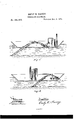
Referring to the drawings, to more fully illustrate and describe my invention, A VB is a curved tube inserted in the bottom of the dredging-boat, at an angle of forty-five degrees or. less in the middle of the boat at the orifices s and 0. At A is a screw-propeller. At A O and D E are sheaths or casings of tubular form, fitting the portions of the curved tube which they inclose, and resting solid and water-tight on the hull of the boat, and reaching above the water-line. The object of this casing i to prevent the filling of the boat with water, when the whole or a part of the curved tube is removed.
The boat being secured in its place, and steam-power being applied by the engine W through the crank S, the propeller revolves and moves the water throughout the tube, discharging it upon the ground or river-bottom at B, according to the course and conditions described in my application for Letters Patent for improvement in propulsion of vessels. The force of the water from the discharge-tube, striking at an angle of forty-five degrees or less, will Wash out and excavate the ground in the river-bottom.
The advantages gained over the method of conducting the water in a straight tube direct from S to B are, first, the propeller operates on a larger body of water than it would if a tube of the same diameter led direct from S to B, and that water strikes as a unit upon an obstruction at B, with the force of the moving column from A to B; second, the forceof the propeller is exerted on the water gravitating from V-a higher point than S; consequently a greater vacuum is produced at V, to which the Wat 1' from A must rush, relieving the propeller, and making a high velocity easily attained.
The boat being released and free to move, and the continuation of the curved tube below the hull being removed, the siphon-propeller shall be used for the propulsion of the vessel, the propeller being placed in the middle of the boat, as in Fig. 1, or at the bow and fore part of the boat, as at Fig. 2.
The object of this claim is to secure Letters Patent for an apparatus for dredging by means of water projected in a parabola in an air-tight tube, and also to supply a defect in my application for an improvement in propulsion of vessels, filed April 25, 1874, and which is now pending, wherein the curved tube is disproportionately long, and this correction is to secure the proper efl'ect of the invention by placing it as above described.
Having thus described my invention, what I claim, and desire to secure by Letters Patent, is-
The combination of the boat L with an upwardly-curved tube, containing. a propellerwheel operated by suitable mechanism, the opposite ends of said tube inserted through the hull of the vessel at difierent points, fore and aft, of said vessel, for entrance and exit of the water, the tube being prolonged and extending toward the bed of the place to be dredged, all constructed and arranged as shown and specified.
In testimony whereof I, the said EMILY E. TASSEY, have hereunto set my hand.
EMILY E. TASSEY.
Witnesses:
JAMES A. MCKEAN, H. B. WILKINS.
Publications (1)
| Publication Number | Publication Date |
|---|---|
| US184998A true US184998A (en) | 1876-12-05 |
Family
ID=2254403
Family Applications (1)
| Application Number | Title | Priority Date | Filing Date |
|---|---|---|---|
| US184998D Expired - Lifetime US184998A (en) | Improvement in dredging-machines |
Country Status (1)
| Country | Link |
|---|---|
| US (1) | US184998A (en) |
Cited By (3)
| Publication number | Priority date | Publication date | Assignee | Title |
|---|---|---|---|---|
| US2500354A (en) * | 1945-02-24 | 1950-03-14 | Frederic R Harris | Apparatus for controlling silt accumulation |
| US3964184A (en) * | 1973-06-25 | 1976-06-22 | Mathieu Thomas A | Method of removing material from a bed of a body of water |
| US5546682A (en) * | 1994-10-05 | 1996-08-20 | Skerry; Eric | Sediment relocation machine |
-
0
- US US184998D patent/US184998A/en not_active Expired - Lifetime
Cited By (3)
| Publication number | Priority date | Publication date | Assignee | Title |
|---|---|---|---|---|
| US2500354A (en) * | 1945-02-24 | 1950-03-14 | Frederic R Harris | Apparatus for controlling silt accumulation |
| US3964184A (en) * | 1973-06-25 | 1976-06-22 | Mathieu Thomas A | Method of removing material from a bed of a body of water |
| US5546682A (en) * | 1994-10-05 | 1996-08-20 | Skerry; Eric | Sediment relocation machine |
Similar Documents
| Publication | Publication Date | Title |
|---|---|---|
| SE443762B (en) | RADIATION DRIVER FOR DRIVING AND CONTROL OF PLANNING BATES | |
| US442615A (en) | Marine propulsion | |
| US39394A (en) | Improved apparatus for marine propulsion | |
| US985187A (en) | Boat. | |
| US184997A (en) | Improvement in propulsion of vessels | |
| US2134042A (en) | Boat | |
| US120264A (en) | Improvement in propulsion of vessels | |
| US464898A (en) | Screw propeller | |
| US389330A (en) | Henry | |
| US119363A (en) | Improvement in propulsion of vessels | |
| US1543026A (en) | Propelling system and method | |
| US441965A (en) | Propulsion of vessels | |
| US3513798A (en) | Steering device for vessels | |
| US1159946A (en) | Bilge-water extractor. | |
| US615866A (en) | Submarine boat | |
| US471274A (en) | Screw-propulsion of vessels | |
| US624271A (en) | Pneumatic propulsion means | |
| US208952A (en) | Improvement in propelling vessels | |
| US229000A (en) | Ghaeles g | |
| US806222A (en) | Construction of vessels. | |
| US630254A (en) | Form for hulls of vessels. | |
| US597632A (en) | Screw-propeller | |
| US871236A (en) | Vessel-propelling means. | |
| US259998A (en) | Means of propelling vessels | |
| US987794A (en) | Bow-facing manually-operated boat-propelling apparatus. |