US184946A - Improvement in inking apparatus for printing-presses - Google Patents
Improvement in inking apparatus for printing-presses Download PDFInfo
- Publication number
- US184946A US184946A US184946DA US184946A US 184946 A US184946 A US 184946A US 184946D A US184946D A US 184946DA US 184946 A US184946 A US 184946A
- Authority
- US
- United States
- Prior art keywords
- rollers
- roller
- boxes
- presses
- printing
- Prior art date
- Legal status (The legal status is an assumption and is not a legal conclusion. Google has not performed a legal analysis and makes no representation as to the accuracy of the status listed.)
- Expired - Lifetime
Links
- 229960001948 caffeine Drugs 0.000 description 1
- 238000010276 construction Methods 0.000 description 1
- 230000000694 effects Effects 0.000 description 1
- RYYVLZVUVIJVGH-UHFFFAOYSA-N trimethylxanthine Natural products CN1C(=O)N(C)C(=O)C2=C1N=CN2C RYYVLZVUVIJVGH-UHFFFAOYSA-N 0.000 description 1
Images

Classifications
-
- B—PERFORMING OPERATIONS; TRANSPORTING
- B41—PRINTING; LINING MACHINES; TYPEWRITERS; STAMPS
- B41F—PRINTING MACHINES OR PRESSES
- B41F31/00—Inking arrangements or devices
- B41F31/15—Devices for moving vibrator-rollers
Definitions
- the invention relates to certain improved means for adjusting the form and distributing rollers, whereby thewipin g action of the formroller on the form, which, when repeated, results in the filling up of more or less of the fine lines in the type and engravings, and thereby producing a correspondingly blurred and indistinct impression, is prevented.
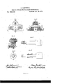
- Figure l is an end elevation of the distributing and form rollers, arranged in thein bearings. a cross-section through the boxes at one end.
- Fig. 3 is a vertical longitudinal section in line a; as, Fig. 1.
- Fig. 4 is a vertical longitudinal section of one ofthe boxes of the distributingroller.
- Fig. 5 is an end view of one of the form-rollers and its box detached.
- Fig. 6 is an elevation of a portion of one of the form-rollers, with the box in section in line y y of Fig. 5.
- A is the distributing-roller, and B B the form-rollers, of ordinary construction.
- E is the bracket-bearingwhich supports the distributing and form rollers at each end. It is secured by bolts to the top of the side ribs of the frame of the machine.
- 0 are the boxes of the distributing-roller of cylindrical form, the central portion of which is reduced so as to form a cam, c.
- D are boxes of the form-rollers, constructed as will presently be explained. To insure a clear and distinct impression, it is of the utmost importance that the surface of the form-rollers travel in perfect unison with the form, so as to prevent the wiping I action which results from a want of such uni- Fig. 2 isv formity in the movement of these surfaces.
- the pin is arranged so that the pin will lock it in the position shown in Figs. 1 and 3, when it acts as a stopbearing for the form-roller boxes.
- the cam F is turned so as to force outward the form rollers, in which position it is locked and the rollers kept separate by the pin entering the other hole 0.
- the boxes D are adjusted by setscrews 71., which screw through the box and rest with their ends against the edges of the stop F. By turning these set-screws the rollers are adjusted as they shrink, while their proper central position between the form and distributing rollers is accurately maintained.
- the boxes are secured in place by a key, I, which is inserted through a hole in the bracket, so that its upper edge will rest in contact with the central cam c of the distributing roller box, while the lower edge rests on the top of the form-roller boxes.
- the key is tightened by turning the box 0, by means of a suitable wrench-the cam operatating as a wedge to press the key firmly against the boxes.
- the form-rollers are removed with their boxes, which are held thereon by set-sc rews m which project into a transverse groove, a, made around the roller-shaft.
Landscapes
- Inking, Control Or Cleaning Of Printing Machines (AREA)
Description
A. CAMPBELL.
INKING APPARATUS FOR PRINTING-PRESSES. No.134,946. 1 Patented Nov. 28, 1876."
' THE GRAPHIC C0.N.Y
UNITED. STATES PATENT QFFICE.
ANDREW GAMPBELT OF BROOKLYN, NEW YORK.
IMPROVEMENT IN INKING APPARATUS FOR PRINTING-PRESSES.
Specification forming part of Letters Patent N 0. 84,946, dated November 28, 1876; application filed January 26, 1876.
To all whom it may concern:
Be it known that I, ANDREW CAMPBELL, of the city of Brooklyn, in the county ofK-ings and State of New York, have inventedcertain Improvements in Inking Apparatus for Printing-Presses, of which the following is a specifieation:
The improvements which form the subjectmatter of this specification, were included in an application for Letters Patent for improvements in printing-presses, filed by me December 26, 1871, from which it has been withdrawn for the purpose of filing the present application.
The invention relates to certain improved means for adjusting the form and distributing rollers, whereby thewipin g action of the formroller on the form, which, when repeated, results in the filling up of more or less of the fine lines in the type and engravings, and thereby producing a correspondingly blurred and indistinct impression, is prevented.
In the accompanyingdrawings, Figure l is an end elevation of the distributing and form rollers, arranged in thein bearings. a cross-section through the boxes at one end. Fig. 3 is a vertical longitudinal section in line a; as, Fig. 1. Fig. 4 is a vertical longitudinal section of one ofthe boxes of the distributingroller. Fig. 5 is an end view of one of the form-rollers and its box detached. Fig. 6 is an elevation of a portion of one of the form-rollers, with the box in section in line y y of Fig. 5.
Like letters of referencedesignate like parts in each of the figures.
A is the distributing-roller, and B B the form-rollers, of ordinary construction. E is the bracket-bearingwhich supports the distributing and form rollers at each end. It is secured by bolts to the top of the side ribs of the frame of the machine. 0 are the boxes of the distributing-roller of cylindrical form, the central portion of which is reduced so as to form a cam, c. D are boxes of the form-rollers, constructed as will presently be explained. To insure a clear and distinct impression, it is of the utmost importance that the surface of the form-rollers travel in perfect unison with the form, so as to prevent the wiping I action which results from a want of such uni- Fig. 2 isv formity in the movement of these surfaces. To insure this required uniformity of motion, it is essential that the surface of the formrollers press equally against the form and the distributing'roller, as an unequal pressure will cause the surface against which the pressure is the greater to act as a driver, which will cause the two other surfaces in contact to slip or wipe. This will be where there is the least surface in contact, and which almost always proves to be the form, which causes the finer lines in engravings and type to become more or less filled up, thereby producing a correspondingly blurred and imperfect impression, as hereinafter stated. To prevent this result, it becomes of the utmost importance to secure and maintain an accurate central adjustment of the form-rollers between the two points of contact. As the forin rollers are liable to shrink, and consequently require readjustment, a proper adjustment of these rollers becomes a matter of great difficulty. To insure this required adjustment, I construct the boxes D of the form-rollers with a plane surface, 61, on one side, as shown, and construct a bearing surface against which they restinclined, as shown at 0. Theoretically, the faces of these inclines should be made with a curve parallel to'a curved line passing through the centers of three or more circles of unequal diameter, made tangential to the surface of the form andthe surface of the distributing-roller, which circles should correspond in diameter to the diameter of the different sizes of form-rollers intended to be used. For practical purposes, a line drawn through the centers of two circles corresponding with, or approximating in diameter, the two extreme sizes of the form-rollers will be sufficiently accurate.
F is a stop and separating cam, arranged in an openingin the center of the bracket E, and secured to a shaft, f, the end of which projects outsideof the bracket, and terminates in a milled wheel, f, by which the cam is operated. To retain the cam in its proper position, when adjusted, two holes, ee, are
made in the face of the bracket, and a pin, f
arranged to project from the contiguous face of the hand-wheel and engage in said holes. The inner portion of the hole in the bracket around the shaft f is enlarged to receive a spiral spring, g, which operates to keep the handwheel pressed against the face of the bracket. One of the holes, e, is arranged so that the pin will lock it in the position shown in Figs. 1 and 3, when it acts as a stopbearing for the form-roller boxes. To prevent the form-rollers from remaining in contact with the type and distributingfroller when the press is at rest, and thereby impairing the surface of the form-roller, the cam F is turned so as to force outward the form rollers, in which position it is locked and the rollers kept separate by the pin entering the other hole 0. The boxes D are adjusted by setscrews 71., which screw through the box and rest with their ends against the edges of the stop F. By turning these set-screws the rollers are adjusted as they shrink, while their proper central position between the form and distributing rollers is accurately maintained. When adjusted, the boxes are secured in place by a key, I, which is inserted through a hole in the bracket, so that its upper edge will rest in contact with the central cam c of the distributing roller box, while the lower edge rests on the top of the form-roller boxes. The key is tightened by turning the box 0, by means of a suitable wrench-the cam operatating as a wedge to press the key firmly against the boxes. If the form-rollers become much reduced in size, a \viderkey will be required. By constructing the key with a central enlargement on one edge, and using the key first with this enlargement down, and then reversing it, when a wider key is required, the necessary increase in the width of the key inthe latter case will in effect be produced. To remove the rollers, the key is released by reversing the cam c and withdrawn. The boxes of the distributing rollers are pushed out of the bracket by sliding them on the shaft, when the roller is readily lifted out.
The form-rollers are removed with their boxes, which are held thereon by set-sc rews m which project into a transverse groove, a, made around the roller-shaft.
What I claim as my invention is- 1. The combination, with the form or typebed, form-rollers, and distributing-roller, of
the inclined bearings e for the form-roller boxes, substantially as and for the purpose hereinbefore set forth.
2. The cylindrical box of the distril'iutingroller, constructed with a tightening-cam, c, as and for the purpose set forth.
3. The combination of the form'roller boxes, and inclined bearings therefor, of the lockingkey, and a tightening-cam, a, substantially as hereinbefore set forth.
4. The combination, with the form roller, of the form-roller boxes, provided with an adjusting-screw, h, and attached to the roller so as to enable both together to be removed and replaced without readjustment, except in case of shrinkage, substantially as hereinbefore set forth. v r
5. The combination, with the inclined bearings e, and form-roller boxes, of the adjusting set-screws, and stop-bearings atthe end of the inclines, substantially as hereinbefore set forth.
6. The combination, with the form -roller boxes and inclined bearings, of the stop and roller-swinging cam for separating the formrollers from contact with the type and disdistributing roller, when the press isnot in use, substantially as hereinbefore set forth.
7. The combination and arrangement, with the bracket-bearing E, of the cam F, spurs and holes f 0, spring g, and hand-wheel f, as hereinbefore specified.
ANDREW CAMPBELL.
. Witnesses:
J. J. VAN WINKLE, A. 0. CAMPBELL.
Publications (1)
| Publication Number | Publication Date |
|---|---|
| US184946A true US184946A (en) | 1876-11-28 |
Family
ID=2254351
Family Applications (1)
| Application Number | Title | Priority Date | Filing Date |
|---|---|---|---|
| US184946D Expired - Lifetime US184946A (en) | Improvement in inking apparatus for printing-presses |
Country Status (1)
| Country | Link |
|---|---|
| US (1) | US184946A (en) |
Cited By (1)
| Publication number | Priority date | Publication date | Assignee | Title |
|---|---|---|---|---|
| WO2019004504A1 (en) | 2017-06-29 | 2019-01-03 | 심형민 | Shower device |
-
0
- US US184946D patent/US184946A/en not_active Expired - Lifetime
Cited By (1)
| Publication number | Priority date | Publication date | Assignee | Title |
|---|---|---|---|---|
| WO2019004504A1 (en) | 2017-06-29 | 2019-01-03 | 심형민 | Shower device |
Similar Documents
| Publication | Publication Date | Title |
|---|---|---|
| US679413A (en) | Rolling-mill. | |
| US358473A (en) | John nuebling | |
| US1107772A (en) | Printing-press. | |
| US861823A (en) | Arrangement for removal of rolls in printing-presses. | |
| US1271888A (en) | Adjustable bearing-block. | |
| US285421A (en) | Printing-press | |
| US262938A (en) | Peters | |
| US1325760A (en) | sheldon | |
| US588231A (en) | Flat-form rotary printing-press | |
| US943218A (en) | Ink-fountain for printing-presses. | |
| US835784A (en) | Inking-fountain for printing-presses. | |
| US427650A (en) | Island | |
| US640808A (en) | Printing-press. | |
| US1095275A (en) | Stenciling-machine. | |
| US178328A (en) | Improvement in printing-presses | |
| US315286A (en) | Hand-stamp | |
| US590790A (en) | Ink-fountain for printing-presses | |
| US382979A (en) | Inking apparatus for printing-machines | |
| US558214A (en) | Edward p | |
| US873404A (en) | Side bearing for cars. | |
| US282956A (en) | Andeew campbell | |
| US608774A (en) | Half to the edward p | |
| US427450A (en) | Inking apparatus for printing-presses | |
| US627368A (en) | Kenburgh | |
| US673201A (en) | Drawing-board. |