US1831070A - Winding means for spring motors - Google Patents
Winding means for spring motors Download PDFInfo
- Publication number
- US1831070A US1831070A US245922A US24592228A US1831070A US 1831070 A US1831070 A US 1831070A US 245922 A US245922 A US 245922A US 24592228 A US24592228 A US 24592228A US 1831070 A US1831070 A US 1831070A
- Authority
- US
- United States
- Prior art keywords
- hub
- bore
- spring
- arbor
- handle
- Prior art date
- Legal status (The legal status is an assumption and is not a legal conclusion. Google has not performed a legal analysis and makes no representation as to the accuracy of the status listed.)
- Expired - Lifetime
Links
- 238000004804 winding Methods 0.000 title description 7
- 229920001817 Agar Polymers 0.000 description 1
- 239000008272 agar Substances 0.000 description 1
- 238000010276 construction Methods 0.000 description 1
Images
Classifications
-
- F—MECHANICAL ENGINEERING; LIGHTING; HEATING; WEAPONS; BLASTING
- F03—MACHINES OR ENGINES FOR LIQUIDS; WIND, SPRING, OR WEIGHT MOTORS; PRODUCING MECHANICAL POWER OR A REACTIVE PROPULSIVE THRUST, NOT OTHERWISE PROVIDED FOR
- F03G—SPRING, WEIGHT, INERTIA OR LIKE MOTORS; MECHANICAL-POWER PRODUCING DEVICES OR MECHANISMS, NOT OTHERWISE PROVIDED FOR OR USING ENERGY SOURCES NOT OTHERWISE PROVIDED FOR
- F03G1/00—Spring motors
- F03G1/02—Spring motors characterised by shape or material of spring, e.g. helical, spiral, coil
- F03G1/022—Spring motors characterised by shape or material of spring, e.g. helical, spiral, coil using spiral springs
-
- F—MECHANICAL ENGINEERING; LIGHTING; HEATING; WEAPONS; BLASTING
- F03—MACHINES OR ENGINES FOR LIQUIDS; WIND, SPRING, OR WEIGHT MOTORS; PRODUCING MECHANICAL POWER OR A REACTIVE PROPULSIVE THRUST, NOT OTHERWISE PROVIDED FOR
- F03G—SPRING, WEIGHT, INERTIA OR LIKE MOTORS; MECHANICAL-POWER PRODUCING DEVICES OR MECHANISMS, NOT OTHERWISE PROVIDED FOR OR USING ENERGY SOURCES NOT OTHERWISE PROVIDED FOR
- F03G1/00—Spring motors
- F03G1/06—Other parts or details
- F03G1/08—Other parts or details for winding
Definitions
- My invention relates particularly to the power spring winding -means of spring driven motion picture cameras and has for its general object the provision of a simple,
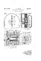
- Figure 2 is a partial transverse vertical locking mechanism unnecessary to-be de-- scribed. See Figures 1- and 2.
- a frame plate 3 is secured in the casing intermediate and in parallelism with the sides thereof, and disposed between the closed side of the casing and the frame plate 3 is a spring motor which will now be described.
- FIG. 1 is a partial side elevation of a spring driven motion picture camera em-- Disposed between the closed side of thef casing 1 and the frame plate 3 is a circular spring housing 8 provided with a flanged central opening by means of which thehousing is journaled on the exterior of the hub 4 on opposite sides of an intermediate exte *rior enlargement 9 of the hub, as designated filed August 30, 1926, for improvementin at 10. Disposed Within the spring housing 8 is a" spiral power spring 11 which has its inner end secured to the enlargement9 of the hub 4 and its outerend secured to the housing manner unnecessary to be described. f I
- the spring 11 iswound by rotation of the hub .4 in the proper direction, an'automatic check mechanism, not shown, preventing rotation of the hub 4 in the opposite direction to unwind the spring through a gear 12 dis posed'between the closed side of the casing and the spring housing 8 and rotatably secured on the hub4.
- Theen'ergy of the spring 11 is expended by rotation thereby of the housing 8 which is operatively connected to hub to form an inner bearing therefor, this operate the mechanism of thecamera by means of gear teeth 13 on the periphery of the housing 8.
- The'h'ub 4 is rotated in the proper direction, counterclockwise in Figure 4. from the-exterior of the casing 1 to wind the spring 11 by mechanism which will now be described.
- An arbor 14 is journaled in the bore of the hub 4 and has the inner end thereof enlarged, as designated at 15, and disposed in the enlarged inner end 7 of the bore of the hub whereby the shoulders formed by Q '90 r the enlarged'inner end 7 of the bore of the hub and by the enlarged inner end 15; of
- the arbor engage to prevent outward: longitud nal movement of the arbor with respect is provided with longitudinally extending notches 16 spaced therearound, and the arbor "to the hub, as designated at 26 in Figure t See Figures 2' and 3. .
- the bore 'of the hub 4' 14 is provided with longitudinally extending slots 17 extending inwardly from'the periph ery thereof, on chords thereof. See partic ularly Figure 4.
- Ratchet members 18 extend longitudinally of the arbor 14 and are movably engaged in the slots 17.
- Bow springs 19 are disposed in the slots 17 and are opera-- tive between the bottoms of the slots and the ratchet members to-yieldably urge the ratchet members into engagement'with the notches lti of the hub 4 to form an automatic one way driving connection therebetween.
- the inner ends of thebow springs'19 are angled and project over the inner ends of the ratchet members 18, as designated at .20, to longitudinally confine the springs.
- the outer end of the arbor14 projectszoutwardly of the outer end of the hub 4 and the corresponding wall of the casing 1, and
- A'handle member 22 is disposed immediately exterior -'Of the closed side wall of the casing 1 in a plane: corresponding therewith and transversely of the arbor 14, and has its'intermediate portion secured on the outer end of thearbor by-meansof an intermediate bore thereof corresponding with the outer end of thearbor and engaged thereon and a headed screw 23 screwthreaded into the outer end ofthe arbor and inwardly engaging the hanrdle member 22 with'its head.
- a bail handle 24 has its .ends reduced, as designated at 25 in Figures land 2, and sprung into recesses in the ends of the handle member22 whereby the bail handle 24 is carried on the handle member 22 for pivotal movement onanaxis corresponding with th-e'plane'ot movement of the handle member 22 and with theplane of the adjacent wall of the casing 1.
- the bail. handle when not in use,-may be swung to'a position overlying-the adjacent wall of the casing 1 so that it "does "not inconveniently project therefrom.
- the-spring 11 may be wound by giving the handle an oscillating or back and torthmove- 'ment, andwhen desired the bail-handle may be utilized as a carrying handle for the camera.
- WVhile I have herein shown and'particularly described my invention in its'preferred theprecise details of construction as changes 'may readily be made withoutdepartmgfrom desire to secure by Letters Patent the 01- -lowingz bore otthe huband provided with longitudinally extending slots extending inwardly ,zirom the periphery thereof on chords ofthe with notches.
- a-spring motor includingan axially bored revolublehub provided r-ritl longitudinally extending'notches inithe bore thereof and havingrthe inner/end of said bore enlarged, OfdILaIbOI journaled in the arbor, said arborihaving its'inner end enlarged "and disposed inthe enlarged inner end ofthe bore-f the hub, a stationary bearing member engaged in the inner end ofthe hub toit'orin: aninner-bearing therefor,*ratch- Vet: members extending longitudinally of said arbor and movably Vengagediin said slots," bow springs in said slots and operative between a thebottoms' ofthe slots and said ratchet members to yieldabryurgesaid ratchet members into engagement with saidnotches and havingitheir innerrends angled and prOJectmg over the inner ends of said'ratchet members, a handlemember disposed transversely of said arbor and having its intermediate portion secured to the
Landscapes
- Engineering & Computer Science (AREA)
- Chemical & Material Sciences (AREA)
- Combustion & Propulsion (AREA)
- Mechanical Engineering (AREA)
- General Engineering & Computer Science (AREA)
- Connection Of Motors, Electrical Generators, Mechanical Devices, And The Like (AREA)
Description
Nov. 10, 1931. A. s. HOWELL WINDING MEANS FOR SPRING MOTORS Filed Jan. 11, 1928 agar ya Patented Nov. 10, 1931 UNITED STATES PATENT FF CE ALBERT S. HOWELL, OF CHICAGO, ILLINOIS, ASSIGNOR TO THE BELL & HOWELL COM- PANY, OF CHICAGO, ILLINOIS, A. CORPORATION OF ILLINOIS WINDING MEANS rcn srnnve Morons Application filed. January 11, 1928. Serial No. 245,922.
My invention relates particularly to the power spring winding -means of spring driven motion picture cameras and has for its general object the provision of a simple,
compact, and convenient means for winding the power spring of a motion picture camera, and particularly with a view toward the provision of such a winding means for a motion picture camera of the type disclosed and claimed in my co-pending application for U. S. Letters Patent, Serial No. 132,475,
motion picture camera and the like.
The invention will be better understood by reference to the accompanying drawings, 1n
which hodying my present invention vwith parts broken away;
Figure 2 is a partial transverse vertical locking mechanism unnecessary to-be de-- scribed. See Figures 1- and 2.
A frame plate 3 is secured in the casing intermediate and in parallelism with the sides thereof, and disposed between the closed side of the casing and the frame plate 3 is a spring motor which will now be described.
The end of the casing 1, which is shown, is
semicircular on a transverse axis, and dis posed on this axis is a coaXially bored hub 4 which is mounted for rotation by means of the outer end of the hub being journaled in a bore through the side wall of the casing, as designated at 5, and by means of a bearing member 6 secured on the frame plate 3 and engaging the inner end of the bore of the 8 in a suitable Figure 1 is a partial side elevation of a spring driven motion picture camera em-- Disposed between the closed side of thef casing 1 and the frame plate 3 is a circular spring housing 8 provided with a flanged central opening by means of which thehousing is journaled on the exterior of the hub 4 on opposite sides of an intermediate exte *rior enlargement 9 of the hub, as designated filed August 30, 1926, for improvementin at 10. Disposed Within the spring housing 8 is a" spiral power spring 11 which has its inner end secured to the enlargement9 of the hub 4 and its outerend secured to the housing manner unnecessary to be described. f I
The spring 11 iswound by rotation of the hub .4 in the proper direction, an'automatic check mechanism, not shown, preventing rotation of the hub 4 in the opposite direction to unwind the spring through a gear 12 dis posed'between the closed side of the casing and the spring housing 8 and rotatably secured on the hub4. Theen'ergy of the spring 11 is expended by rotation thereby of the housing 8 which is operatively connected to hub to form an inner bearing therefor, this operate the mechanism of thecamera by means of gear teeth 13 on the periphery of the housing 8. I
The'h'ub 4 is rotated in the proper direction, counterclockwise in Figure 4. from the-exterior of the casing 1 to wind the spring 11 by mechanism which will now be described. An arbor 14 is journaled in the bore of the hub 4 and has the inner end thereof enlarged, as designated at 15, and disposed in the enlarged inner end 7 of the bore of the hub whereby the shoulders formed by Q '90 r the enlarged'inner end 7 of the bore of the hub and by the enlarged inner end 15; of
the arbor engage to prevent outward: longitud nal movement of the arbor with respect is provided with longitudinally extending notches 16 spaced therearound, and the arbor "to the hub, as designated at 26 in Figure t See Figures 2' and 3. .The bore 'of the hub 4' 14 is provided with longitudinally extending slots 17 extending inwardly from'the periph ery thereof, on chords thereof. See partic ularly Figure 4. Ratchet members 18 extend longitudinally of the arbor 14 and are movably engaged in the slots 17. Bow springs 19 are disposed in the slots 17 and are opera-- tive between the bottoms of the slots and the ratchet members to-yieldably urge the ratchet members into engagement'with the notches lti of the hub 4 to form an automatic one way driving connection therebetween. The inner ends of thebow springs'19 are angled and project over the inner ends of the ratchet members 18, as designated at .20, to longitudinally confine the springs.
The outer end of the arbor14 projectszoutwardly of the outer end of the hub 4 and the corresponding wall of the casing 1, and
is flattenedat'diametrically opposite points,
"as des gnated at 21 in Figure 4. A'handle member 22 is disposed immediately exterior -'Of the closed side wall of the casing 1 in a plane: corresponding therewith and transversely of the arbor 14, and has its'intermediate portion secured on the outer end of thearbor by-meansof an intermediate bore thereof corresponding with the outer end of thearbor and engaged thereon and a headed screw 23 screwthreaded into the outer end ofthe arbor and inwardly engaging the hanrdle member 22 with'its head. A bail handle 24 has its .ends reduced, as designated at 25 in Figures land 2, and sprung into recesses in the ends of the handle member22 whereby the bail handle 24 is carried on the handle member 22 for pivotal movement onanaxis corresponding with th-e'plane'ot movement of the handle member 22 and with theplane of the adjacent wall of the casing 1. As a result the bail. handle, when not in use,-may be swung to'a position overlying-the adjacent wall of the casing 1 so that it "does "not inconveniently project therefrom.
Byreason of'the one way driving connec tion between the arbor 14 and the 'hub 4 the-spring 11 may be wound by giving the handle an oscillating or back and torthmove- 'ment, andwhen desired the bail-handle may be utilized as a carrying handle for the camera.
WVhile I have herein shown and'particularly described my invention in its'preferred theprecise details of construction as changes 'may readily be made withoutdepartmgfrom desire to secure by Letters Patent the 01- -lowingz bore otthe huband provided with longitudinally extending slots extending inwardly ,zirom the periphery thereof on chords ofthe with notches. in'the bore thereof and having the inner end of said bore enlarged, of an ,arborrotatable within the bore of the hub and provided with recesses extending inwardly'from theperiphery thereof and having its inner end enlarged and disposed in the enlargedinnertendi of the bore of the hub, outwardly spring pressed ratchet members movablyrengagedin said recesses and engageable with said notches to form a one way ratchet driving connection between said arbor and hub, anda-winding handle on the outerend of the arbor.
In adevice of the character described the combination with a-spring motor includingan axially bored revolublehub provided r-ritl longitudinally extending'notches inithe bore thereof and havingrthe inner/end of said bore enlarged, OfdILaIbOI journaled in the arbor, said arborihaving its'inner end enlarged "and disposed inthe enlarged inner end ofthe bore-f the hub, a stationary bearing member engaged in the inner end ofthe hub toit'orin: aninner-bearing therefor,*ratch- Vet: members extending longitudinally of said arbor and movably Vengagediin said slots," bow springs in said slots and operative between a thebottoms' ofthe slots and said ratchet members to yieldabryurgesaid ratchet members into engagement with saidnotches and havingitheir innerrends angled and prOJectmg over the inner ends of said'ratchet members, a handlemember disposed transversely of said arbor and having its intermediate portion secured to the outer end thereof, and a bail handle having itsendsrmountedon the ends :o'lisaid handlemembert'or pivotal movement on an'axiscorresponding with the plane of "rotationof said handle memberl In witnesswhereof I hereunto afiix mysignature this v24th day-ofrDecember, 1927.
' ALBERT S. HOXVELL. 4
"embodiment I do not wishto be limited to lit) 1. In a device of the character described 5 the'com'bination'with a spring motor including' anaxially'bored revolublehub havlng the Zinner end of its bore'enlarged, of an arbor rotatable within-the bore of the hub and havdisposed inthe
Priority Applications (1)
| Application Number | Priority Date | Filing Date | Title |
|---|---|---|---|
| US245922A US1831070A (en) | 1928-01-11 | 1928-01-11 | Winding means for spring motors |
Applications Claiming Priority (1)
| Application Number | Priority Date | Filing Date | Title |
|---|---|---|---|
| US245922A US1831070A (en) | 1928-01-11 | 1928-01-11 | Winding means for spring motors |
Publications (1)
| Publication Number | Publication Date |
|---|---|
| US1831070A true US1831070A (en) | 1931-11-10 |
Family
ID=22928644
Family Applications (1)
| Application Number | Title | Priority Date | Filing Date |
|---|---|---|---|
| US245922A Expired - Lifetime US1831070A (en) | 1928-01-11 | 1928-01-11 | Winding means for spring motors |
Country Status (1)
| Country | Link |
|---|---|
| US (1) | US1831070A (en) |
Cited By (2)
| Publication number | Priority date | Publication date | Assignee | Title |
|---|---|---|---|---|
| US3073416A (en) * | 1960-11-29 | 1963-01-15 | Mechanical Swinging Cradle Com | Spring motor for swings |
| EP3351792A4 (en) * | 2015-09-18 | 2019-08-21 | Endo Kogyo Co., Ltd. | SPRING DRIVE DEVICE AND AUTOMATIC DISPLACEMENT WHEEL |
-
1928
- 1928-01-11 US US245922A patent/US1831070A/en not_active Expired - Lifetime
Cited By (2)
| Publication number | Priority date | Publication date | Assignee | Title |
|---|---|---|---|---|
| US3073416A (en) * | 1960-11-29 | 1963-01-15 | Mechanical Swinging Cradle Com | Spring motor for swings |
| EP3351792A4 (en) * | 2015-09-18 | 2019-08-21 | Endo Kogyo Co., Ltd. | SPRING DRIVE DEVICE AND AUTOMATIC DISPLACEMENT WHEEL |
Similar Documents
| Publication | Publication Date | Title |
|---|---|---|
| CN101230822B (en) | Recoil starter | |
| US1831070A (en) | Winding means for spring motors | |
| US2266865A (en) | Starting device | |
| US2591260A (en) | Spring-driven motor | |
| US2092845A (en) | Flashlight | |
| US1572635A (en) | Window-regulator lock | |
| US3560109A (en) | Antiwindmilling | |
| US2741235A (en) | Starter for internal combustion engine | |
| US3164142A (en) | Spring actuated starter for engines | |
| US1282512A (en) | Starter. | |
| US3141240A (en) | Manually operated rotary shaver | |
| US2973754A (en) | Starter for internal combustion engine | |
| US1936555A (en) | Engine starting mechanism | |
| US153054A (en) | Improvement in car-starters | |
| US1255431A (en) | Winding-mount for power-spring. | |
| JPH0125091Y2 (en) | ||
| US1413582A (en) | Winding mechanism | |
| US88447A (en) | Improved railway-car brake and starter | |
| US1155687A (en) | Mechanical starting mechanism for internal-combustion engines. | |
| US2357146A (en) | Signal device | |
| US920120A (en) | Spring-actuated motor. | |
| US1037376A (en) | Starter for internal-combustion engines. | |
| US1942505A (en) | Winding means for spring motors | |
| US294414A (en) | To eobeet j | |
| US1443019A (en) | Film shifter for cameras |