US181832A - Improvement in corn-planters - Google Patents
Improvement in corn-planters Download PDFInfo
- Publication number
- US181832A US181832A US181832DA US181832A US 181832 A US181832 A US 181832A US 181832D A US181832D A US 181832DA US 181832 A US181832 A US 181832A
- Authority
- US
- United States
- Prior art keywords
- planters
- corn
- improvement
- lever
- foot
- Prior art date
- Legal status (The legal status is an assumption and is not a legal conclusion. Google has not performed a legal analysis and makes no representation as to the accuracy of the status listed.)
- Expired - Lifetime
Links
- 240000001973 Ficus microcarpa Species 0.000 description 1
- 230000000994 depressogenic effect Effects 0.000 description 1
- 230000005484 gravity Effects 0.000 description 1
- 238000000034 method Methods 0.000 description 1
- 238000007790 scraping Methods 0.000 description 1
Images

Classifications
-
- A—HUMAN NECESSITIES
- A01—AGRICULTURE; FORESTRY; ANIMAL HUSBANDRY; HUNTING; TRAPPING; FISHING
- A01B—SOIL WORKING IN AGRICULTURE OR FORESTRY; PARTS, DETAILS, OR ACCESSORIES OF AGRICULTURAL MACHINES OR IMPLEMENTS, IN GENERAL
- A01B3/00—Ploughs with fixed plough-shares
- A01B3/04—Animal-drawn ploughs
- A01B3/06—Animal-drawn ploughs without alternating possibility, i.e. incapable of making an adjacent furrow on return journey, i.e. conventional ploughing
- A01B3/12—Two-wheel beam ploughs
Definitions
- the object of our invention is, first, to provide a more expeditious and perfect method of controlling the respective Scrapers of the covering-wheels in such planter; and, second,
- Figure 1 is a general plan view of a machine embodying our invention.
- Fig. 2 is a central vertical section on line a;
- Fig. 3 is a detail view of scraper.
- a A are the ordinary covering-wheels of a two-horse corn-planter, preceded, respectively, by the usual furrow-openers B B.
- the foot-rests a a with their upper 'surfaces shaped to the sole of the foot, are pivoted laterally to the seat-stem b, or can be pivoted at any other convenient point on the frame. From the lower surface of the foot-rests a a, and integral therewith, extend downward the short levers c c.
- the scrapers d d are pivoted horizontally at or near their upper line, and are provided, as part thereof, respectively, with the inward-extending levers f f, the latter being upon, or nearly upon, aline with the scraping or lower edge ofthe Scrapers.
- the inner ends of the levers f f are connected, re-
- the drivers feet remain upon the rests a a, and by rocking his feet backward thereon he brings the lower edges of the Scrapers d d against the periphery of the covering-wheels A A at will, and with any desired degree of force.
- the scrapers Upon the pressure of the drivers heel being withdrawn, the scrapers, by their own gravity, swing or fall away from the wheels, and thus remain until again brought into operation.
- the advantage we claim for this part of our invention is, that it dispenses with the changing ofthe drivers feet, and with the trouble and difficulty of linding the proper place on the scrapers for the feet, as in the old style.
- the foot-rests a a are so placed relatively to the drivers seat as that the drivers feet may comfortably remain upon the rests a a. y
- the foot-lever mis provided with an axle at, and is fulcrumed under, the cross-beam h, by means of lugs fi i, into which the ends of its axle are inserted.
- the short end of the lever m plays loosely through the orifice in the part k, on the rear end of the tongue l.
- the relative distance of the part 7c and the axis of the lever mis varied, the short end of m, by passing through the part lc, adjusts itself to such change of distance.
- k1 represents a lever-frame, extending backward and upward over the axle on either side, and provided with a cross-bar, k2.
- k3 represents a swinging catch, pivoted to the part b, which holds the rear end of the leverframe k2 down when the same is depressed.
- the driver places one or both of his feet on the crossbar on the upper end of the lever m, and pushes forward on the latter.
- Such forcc communicated through the short end of the lever to the rear of the frame holding the runners B B, and, by reason of the axis-fulcrum under the beam h, the force is communicated to the rear of the runners in a direction vertically downward.
Landscapes
- Life Sciences & Earth Sciences (AREA)
- Zoology (AREA)
- Engineering & Computer Science (AREA)
- Mechanical Engineering (AREA)
- Soil Sciences (AREA)
- Environmental Sciences (AREA)
- Transplanting Machines (AREA)
Description
T. A. GALT & G. S. TRACY.
,c oRN PLANTEP..
Patented sept. 5.1875.
N.PETE| .S, PNoTO-LJTHOGRAPHER. WAsmNGTON. DC.
lk"rrnn STATES PATENT OFFIoa.
THOMAS A. GALT AND GEORGE S. TRACY, OF STERLING, ILLINOIS.
IMPROVEMENT IN CORN-PLANTERS.
Specification forming part of Letters Patent No. 181,832, dated September 5, 1876; application filed July 26, 1876.
To all whom it may concern Be it known that we, THOMAS A. GALT and GEORGE S. TRACY, of the city of Sterling, county of Whitesides and State of Illinois, have invented a new and useful Improvement in Corn-Planters, which improvement is fully set forth in the following specification, reference being had to the accompanying drawings.
The object of our invention is, first, to provide a more expeditious and perfect method of controlling the respective Scrapers of the covering-wheels in such planter; and, second,
to provide a simple foot-lever, by which the' driver can readily force the runners or furrow openers of such planter more deeply into the ground, as occasion may demand.
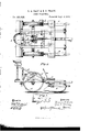
Figure 1 is a general plan view of a machine embodying our invention. Fig. 2 is a central vertical section on line a; Fig. l. Fig. 3 is a detail view of scraper.
A A are the ordinary covering-wheels of a two-horse corn-planter, preceded, respectively, by the usual furrow-openers B B. The usual and ordinary parts of such planter, including the seed-hoppers C C, being fully shown in the drawings, need not be further particularized. The foot-rests a a, with their upper 'surfaces shaped to the sole of the foot, are pivoted laterally to the seat-stem b, or can be pivoted at any other convenient point on the frame. From the lower surface of the foot-rests a a, and integral therewith, extend downward the short levers c c.
The scrapers d d are pivoted horizontally at or near their upper line, and are provided, as part thereof, respectively, with the inward-extending levers f f, the latter being upon, or nearly upon, aline with the scraping or lower edge ofthe Scrapers. The inner ends of the levers f f are connected, re-
spectively, by means of the rods g g, to the lower ends of the short levers c o.
The drivers feet remain upon the rests a a, and by rocking his feet backward thereon he brings the lower edges of the Scrapers d d against the periphery of the covering-wheels A A at will, and with any desired degree of force. Upon the pressure of the drivers heel being withdrawn, the scrapers, by their own gravity, swing or fall away from the wheels, and thus remain until again brought into operation.
The advantage we claim for this part of our invention is, that it dispenses with the changing ofthe drivers feet, and with the trouble and difficulty of linding the proper place on the scrapers for the feet, as in the old style.
The foot-rests a a are so placed relatively to the drivers seat as that the drivers feet may comfortably remain upon the rests a a. y
The foot-lever mis provided with an axle at, and is fulcrumed under, the cross-beam h, by means of lugs fi i, into which the ends of its axle are inserted. The short end of the lever m plays loosely through the orifice in the part k, on the rear end of the tongue l.
As in the different degrees of elevation of the front frame, the relative distance of the part 7c and the axis of the lever mis varied, the short end of m, by passing through the part lc, adjusts itself to such change of distance.
k1 represents a lever-frame, extending backward and upward over the axle on either side, and provided with a cross-bar, k2. k3 represents a swinging catch, pivoted to the part b, which holds the rear end of the leverframe k2 down when the same is depressed.
When it is desired to force the runners more deeply into the ground, the driver places one or both of his feet on the crossbar on the upper end of the lever m, and pushes forward on the latter. Such forcc; communicated through the short end of the lever to the rear of the frame holding the runners B B, and, by reason of the axis-fulcrum under the beam h, the force is communicated to the rear of the runners in a direction vertically downward.
Inasmuch as, in connection with the class of planters referred to, automatic check-droppers which dispense with the weight of the dropper on the runners are being greatly used, and as, also, the ground in which planting is done varies much in density, an ability in the driver to apply, at will, a downward force to the rear of the runners, is a palpable advantage, if not a necessity. This we. ac- 2. The Scrapers d d, pivoted foot-rests a a, complish simply and fully by the use of .the and connections gag, 'in combination, substanlever m and its adjunct parts. tiall'y `as described, and yfor the 4purpose set We claim as our invention, and desire to seforth. cure by Letters Patent- Y l. The foot-lever omfulcrumed, as described, THOMAS A. GALT. under` the cross-beam h, and having the np-l GEO. S. TRACY. Wardly-curved arm, in combination With the part k, the lever-frame k1, and the front frame Witnesses:
of the planter, substantially as and for the GEO.`L. WERNTZ, purpose mentioned. E. LE ROY GALT.
Publications (1)
| Publication Number | Publication Date |
|---|---|
| US181832A true US181832A (en) | 1876-09-05 |
Family
ID=2251238
Family Applications (1)
| Application Number | Title | Priority Date | Filing Date |
|---|---|---|---|
| US181832D Expired - Lifetime US181832A (en) | Improvement in corn-planters |
Country Status (1)
| Country | Link |
|---|---|
| US (1) | US181832A (en) |
Cited By (1)
| Publication number | Priority date | Publication date | Assignee | Title |
|---|---|---|---|---|
| US4185950A (en) * | 1978-09-21 | 1980-01-29 | Lindskog Eric P | Support roller scrapers for wallboard mastic applying apparatus |
-
0
- US US181832D patent/US181832A/en not_active Expired - Lifetime
Cited By (1)
| Publication number | Priority date | Publication date | Assignee | Title |
|---|---|---|---|---|
| US4185950A (en) * | 1978-09-21 | 1980-01-29 | Lindskog Eric P | Support roller scrapers for wallboard mastic applying apparatus |
Similar Documents
| Publication | Publication Date | Title |
|---|---|---|
| US99286A (en) | Improved seed-planter | |
| US59283A (en) | Improvement in seeding-machines | |
| USRE6755E (en) | Improvement in seed-planters | |
| US199344A (en) | Improvement in corn-planters | |
| US115688A (en) | Improvement in combined seeders, planters, and cultivators | |
| US114390A (en) | Improvement in corn-planters | |
| US668397A (en) | Grain-drill. | |
| US37834A (en) | Improvement in corn-planters | |
| US58798A (en) | Improvement in corn and cane planters | |
| US702402A (en) | Seed-drill. | |
| US46271A (en) | Improvement in seeding-machines | |
| US328036A (en) | Corn-planter | |
| US117369A (en) | Improvement in combined corn-planters and fertilizer-distributers | |
| US232689A (en) | Combined listing-plow and seed-planter | |
| USRE3695E (en) | Improvement in corn-planters | |
| US371051A (en) | Corn-planter | |
| US543107A (en) | Potato-planter | |
| US486669A (en) | Seed-planter | |
| US367407A (en) | Lucy a | |
| USRE7083E (en) | Improvement in corn-planters | |
| USRE6385E (en) | Improvement in seed-planters | |
| USRE3148E (en) | Improvement in corn-planters | |
| US162106A (en) | Improvement in corn-planters | |
| US134032A (en) | Improvement in corn-planters | |
| US297961A (en) | Grain-drill |