US1794271A - Grinding machine - Google Patents
Grinding machine Download PDFInfo
- Publication number
- US1794271A US1794271A US335701A US33570129A US1794271A US 1794271 A US1794271 A US 1794271A US 335701 A US335701 A US 335701A US 33570129 A US33570129 A US 33570129A US 1794271 A US1794271 A US 1794271A
- Authority
- US
- United States
- Prior art keywords
- swivelling
- slide
- roll
- block
- rack
- Prior art date
- Legal status (The legal status is an assumption and is not a legal conclusion. Google has not performed a legal analysis and makes no representation as to the accuracy of the status listed.)
- Expired - Lifetime
Links
Images
Classifications
-
- B—PERFORMING OPERATIONS; TRANSPORTING
- B24—GRINDING; POLISHING
- B24B—MACHINES, DEVICES, OR PROCESSES FOR GRINDING OR POLISHING; DRESSING OR CONDITIONING OF ABRADING SURFACES; FEEDING OF GRINDING, POLISHING, OR LAPPING AGENTS
- B24B5/00—Machines or devices designed for grinding surfaces of revolution on work, including those which also grind adjacent plane surfaces; Accessories therefor
- B24B5/02—Machines or devices designed for grinding surfaces of revolution on work, including those which also grind adjacent plane surfaces; Accessories therefor involving centres or chucks for holding work
Definitions
- H. H. lASBRIDGE GRINDING MACHINE Filed Jan. 28. 1929 Patented Feb. 24, 1931v UNITED srA'rEs Parent orrics HARRY HALE-S ASBRIDGE, 0F ASHTON-ON-ME'RSEY, ENGLAND', ASSIG-NOR T0A THE CHURCHILL MACHINE TOOL COMPANY LMITED, OF BROADHEATH, NEAR MAN- CHESTER, ENGLAND, A BRITSH COMPANY,
- This invention relates to grinding inachines, particularly of the type employed for the circular grinding of rolls for rolling mills or for calendering and like machines.
- the said rolls may require to be finished with either a parallel, a convex or a concave surface and the grinding machines for such inishing are, in known practice, provided with a grinding wheel in a relatively iiXed position whilst the roll is carried on a swivelling member mounted on a reciprocating table.
- the object of this invention is to provide improved means for effecting the swivelling of the roll or work support and for the ready and reliable variation of the amount and direction of such swivelling to suit varying requirements.
- the invention comprises the improved combinations and arrangements of parts hereinafter described and claimed.
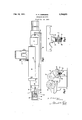
- Figure l is a plan and Figure 2 an end view representing in diagrammatic form or outline a roll grinding machine with this invention applied thereto.
- Figure 3 is an end view showing the rack mechanism to a larger scale than that of Figures l and 2.
- the auXiliary or sliding' rack' c imparts to the'block g a sliding movement at a rate differing from the rate of the table movement.
- the rate of movement of the block g will exceed thatl of the table because the pinion e has a larger number of teeth than the pinion cZ.
- the end of the lever j engaged in the groove will have a corresponding angular movement about its pivot.
- the end 7c of the said lever will therefore operate the swivelling work support Z so that the roll a or the work mounted upon said support and rotated in any convenient and ordinary manner in contact with the grinding wheel o, will have a spherical contour imparted to it, either convex or concave, depending on the angle to which the groove of the disc z' may be set.
- the lever j has an extension or bell crank arm p which is connected by the rod g to the lever r at the opposite end of the swivelling support Z.
- the grooved disc z' with associated parts for effecting the swivelling movements of the work support Z are arranged therewith in any convenient manner.
- the means for swivelling the roll support from the grooved disc comprising a lever pivoted on the slide engaging said f groove and also one end of said roll support,
Description
Felf 24, 1931.
H. H. lASBRIDGE GRINDING MACHINE Filed Jan. 28. 1929 Patented Feb. 24, 1931v UNITED srA'rEs Parent orrics HARRY HALE-S ASBRIDGE, 0F ASHTON-ON-ME'RSEY, ENGLAND', ASSIG-NOR T0A THE CHURCHILL MACHINE TOOL COMPANY LMITED, OF BROADHEATH, NEAR MAN- CHESTER, ENGLAND, A BRITSH COMPANY,
GRIN DING MACHINE Application filed January 28, 1929, Serial No. 335,2'02l.,A and-in; Great Britain February 29, 1928.
This invention relates to grinding inachines, particularly of the type employed for the circular grinding of rolls for rolling mills or for calendering and like machines. The said rolls may require to be finished with either a parallel, a convex or a concave surface and the grinding machines for such inishing are, in known practice, provided with a grinding wheel in a relatively iiXed position whilst the roll is carried on a swivelling member mounted on a reciprocating table.
The object of this invention is to provide improved means for effecting the swivelling of the roll or work support and for the ready and reliable variation of the amount and direction of such swivelling to suit varying requirements.
The invention comprises the improved combinations and arrangements of parts hereinafter described and claimed.
Referring to the accompanying sheet of explanatory drawings Figure l is a plan and Figure 2 an end view representing in diagrammatic form or outline a roll grinding machine with this invention applied thereto.
Figure 3 is an end view showing the rack mechanism to a larger scale than that of Figures l and 2.
Like reference letters in the dierent views indicate like parts.
In the application of the invention as illustrated by the drawings, there is provided be neath the reciprocating table a. of the machine a rack Z) which is lined to said table and an auxiliary rack c which is capable of a sliding movement relatively to said table. The said racks are respectively in mesh with pinions Z and e having diiierent numbers of teeth thereon which are preferably formed integrally with each other and mounted on the shaft Attached to one end of the auxiliary sliding rack c is a block g (shown at the Alett hand end of Figure l) adapted to slide in the guide-ways Zt of the table a. The said block g has arranged therewith a grooved disc z' capable of being set with its groove either parallel or in alignment with the longitudinal centre line of the table a of a swivelling movement about a cent-re as m.
As the table a is reciprocated, the auXiliary or sliding' rack' c imparts to the'block g a sliding movement at a rate differing from the rate of the table movement. In the eX- ample illustrated the rate of movement of the block g will exceed thatl of the table because the pinion e has a larger number of teeth than the pinion cZ. With the grooved disc t' set at an angle to the line of travel of the table a, as indicated at Figure l, the end of the lever j engaged in the groove will have a corresponding angular movement about its pivot. The end 7c of the said lever will therefore operate the swivelling work support Z so that the roll a or the work mounted upon said support and rotated in any convenient and ordinary manner in contact with the grinding wheel o, will have a spherical contour imparted to it, either convex or concave, depending on the angle to which the groove of the disc z' may be set.
For the correct movement of both ends of the swivelling work support Z (which may be of considerable length) and the prevention of lag or lost motion due to bending or other stresses, the lever j has an extension or bell crank arm p which is connected by the rod g to the lever r at the opposite end of the swivelling support Z.
AvWhen the reciprocatory table a is operated otherwise than througlr rack and pinion mechanism, as for example by a screw and nut device or by hydraulic power mechanism, the grooved disc z' with associated parts for effecting the swivelling movements of the work support Z are arranged therewith in any convenient manner.
`What l claim is l. In roll grinding machines., in combination, a grinding wheel, a slide reciprocable upon the machine bed, a roll support swivelling about a vertical pivot upon said slide, guide ways in an extension of said slide, a block reciprocable in said guide ways, and means for its reciprooation relatively to the slide, a grooved-disc capable of being swivelled in said block and set at any angle to the direction of reciprocation of the block, and means engaging the groove in said'disc and operatively connected to the opposite ends of said roll support for imparting swivelling movements to the latter.
2. In roll grinding machinesA as claimed 1n claim l, means for reciprocating the slide and the block in the guide ways in said slide,
comprising a rack secured to said slide and a second rack guided in said slide and connected to said block, and two interconnected driving pinions having different numbers of teeth engaging said two racks.
3. In roll grinding machines as claimed in claim l, the means for swivelling the roll support from the grooved disc, comprising a lever pivoted on the slide engaging said f groove and also one end of said roll support,
an arm upon said lever, a further lever also pivoted upon the slide engaging the other end of saidroll support,-and a rod connecting said arm and said further lever.
In testimony whereof I have signed my name to this specication. HARRY HALES ASBRIDGE.
Applications Claiming Priority (1)
| Application Number | Priority Date | Filing Date | Title |
|---|---|---|---|
| GB1794271X | 1928-02-29 |
Publications (1)
| Publication Number | Publication Date |
|---|---|
| US1794271A true US1794271A (en) | 1931-02-24 |
Family
ID=10890761
Family Applications (1)
| Application Number | Title | Priority Date | Filing Date |
|---|---|---|---|
| US335701A Expired - Lifetime US1794271A (en) | 1928-02-29 | 1929-01-28 | Grinding machine |
Country Status (1)
| Country | Link |
|---|---|
| US (1) | US1794271A (en) |
Cited By (3)
| Publication number | Priority date | Publication date | Assignee | Title |
|---|---|---|---|---|
| US2569005A (en) * | 1949-06-07 | 1951-09-25 | Kindling Alexander | Machine-tool fixture |
| US2730843A (en) * | 1954-06-25 | 1956-01-17 | Cincinnati Milling Machine Co | Cambering mechanism |
| US3398489A (en) * | 1966-02-03 | 1968-08-27 | Jones William T | Roll grinding machine |
-
1929
- 1929-01-28 US US335701A patent/US1794271A/en not_active Expired - Lifetime
Cited By (3)
| Publication number | Priority date | Publication date | Assignee | Title |
|---|---|---|---|---|
| US2569005A (en) * | 1949-06-07 | 1951-09-25 | Kindling Alexander | Machine-tool fixture |
| US2730843A (en) * | 1954-06-25 | 1956-01-17 | Cincinnati Milling Machine Co | Cambering mechanism |
| US3398489A (en) * | 1966-02-03 | 1968-08-27 | Jones William T | Roll grinding machine |
Similar Documents
| Publication | Publication Date | Title |
|---|---|---|
| US1794271A (en) | Grinding machine | |
| US3589072A (en) | Finishing machine | |
| US1970000A (en) | Crowning attachment for roll grinding machines | |
| DE20309306U1 (en) | Surface finishing sanding machine for wooden components has eccentric-mounted roller continuously moved by lever action | |
| US3157091A (en) | Feed mechanism | |
| US1419073A (en) | Setts | |
| US1045022A (en) | Metal-rolling machine. | |
| US2053597A (en) | Machine for generating cams of the worm type | |
| US2063668A (en) | Roll grinding machine | |
| US1707991A (en) | Device for bending rails, pipes, and the like | |
| US1841852A (en) | Machine for grinding the teeth of gear wheels and for other like purposes | |
| US2294045A (en) | Gear grinding machine | |
| US2040820A (en) | Roll grinding machine | |
| US3134201A (en) | Surface finishing machine | |
| US1929966A (en) | Gauge mechanism for grinding machines and the like | |
| US262954A (en) | Alphonse krieger | |
| US250691A (en) | Machine foe grindim | |
| US2096731A (en) | Apparatus for handling and decorating articles of manufacture | |
| US2637949A (en) | Process and machine for surfacing glass | |
| US3046702A (en) | Device for grinding work surfaces curved in the longitudinal direction | |
| US1788249A (en) | Grinding and polishing machine | |
| US2020443A (en) | Compensating means for gear tooth grinders | |
| US1006550A (en) | Grinding-machine. | |
| US342935A (en) | seyee | |
| US2286596A (en) | Roll finisher |