US1791569A - Delivery mechanism - Google Patents
Delivery mechanism Download PDFInfo
- Publication number
- US1791569A US1791569A US122555A US12255526A US1791569A US 1791569 A US1791569 A US 1791569A US 122555 A US122555 A US 122555A US 12255526 A US12255526 A US 12255526A US 1791569 A US1791569 A US 1791569A
- Authority
- US
- United States
- Prior art keywords
- platforms
- supports
- helical
- pads
- pair
- Prior art date
- Legal status (The legal status is an assumption and is not a legal conclusion. Google has not performed a legal analysis and makes no representation as to the accuracy of the status listed.)
- Expired - Lifetime
Links
- 230000007246 mechanism Effects 0.000 title description 30
- 239000011295 pitch Substances 0.000 description 15
- 230000003467 diminishing effect Effects 0.000 description 8
- 230000033001 locomotion Effects 0.000 description 7
- 239000000463 material Substances 0.000 description 4
- 238000010409 ironing Methods 0.000 description 3
- 238000007599 discharging Methods 0.000 description 2
- 230000005484 gravity Effects 0.000 description 2
- 101100462972 Mus musculus Pcdh8 gene Proteins 0.000 description 1
- 208000003251 Pruritus Diseases 0.000 description 1
- 230000005540 biological transmission Effects 0.000 description 1
- 230000000694 effects Effects 0.000 description 1
- 238000011010 flushing procedure Methods 0.000 description 1
- 238000012856 packing Methods 0.000 description 1
- 238000007665 sagging Methods 0.000 description 1
Images


Classifications
-
- B—PERFORMING OPERATIONS; TRANSPORTING
- B65—CONVEYING; PACKING; STORING; HANDLING THIN OR FILAMENTARY MATERIAL
- B65H—HANDLING THIN OR FILAMENTARY MATERIAL, e.g. SHEETS, WEBS, CABLES
- B65H45/00—Folding thin material
- B65H45/12—Folding articles or webs with application of pressure to define or form crease lines
- B65H45/20—Zig-zag folders
Definitions
- This invention relates to machines for carrying to and delivering folded strips of paper at a desired station, and particularly to means for packing the same in pads of a predetermined number of folds and guiding the same to delivery trough in which the same are automatically carried to the station where they may be manually or automatically taken from the machine.
- a principal object of my invention is to guide the folded strips to a trough, compressing each pad thereof into a compact form in its travel to said trough.
- Another object of my invention is to carry the folded pads in said trough to a position where they may be discharged from the machine.
- Another object of my invention is to maintain the pads in proper alignment while heing passed through the guiding mechanism.
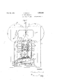
- Fig. 1 is an end View of my machine showing the trough in cross section
- Fig. 2 is a vertical, central, longitudinal section, looking toward the left of Fig. 1;
- Fig. 3 is a side view of a. slightly modified form of my machine embodying the transmission mechanism.
- Fig. 4 is a transverse cross section of the trough and carrier belts.
- 5 representsthe frame of the machine in which the drums 6 and 7 are mounted to rotate with the shafts 8 and 9 respectively, journaled in the frame 5 of the machine.
- These drums are provided with alternate tucker blades 10 and slots 11, the drums being geared so that the blades of one drum will register with the slots of the other drum and the blades of the latter drum will register with the slots of the former drum, in'the rotation'of said drums.
- a spring pressed gripper 12 adapted tobe rocked on the rod 13.
- Beneath the drum assembly just described is a. lowering assembly in which is shown a pair of coacting revolvable supports 15 and Serial No. 122,555.
- a guide frame is mounted in the trough 7, having the upright rails 28, the cross piece 29 and the side pieces 30.
- This frame is sufficiently inclined to cause the pads, as they pass through the lowering mechanism, to rest against the rails 23 of the back of the frame and be confined sidewise by the sup ports 23 and 24, thus maintaining proper alignment of the pads on their way to the rough 27.
- the platform supports are also lightly inclines. to compensate for the inclination of the platforms 25 and 26 due to their itch, which inclination is sufficient to cause the pads falling thereon to naturally assume a position against the back rails 28.
- a sprocket wheel 31 On the. shaft 8 is a sprocket wheel 31 rotatable with said shaft. Adapted to be driven by said sprocket wheel is the chain 32 which passes over the sprocket wheel 33 keyed to the shaft 34 at theother end of which is mounted the bevelled gear 05 to rotate therewith. This gear 35 is in mesh with the bevelled gear 36 on the shaft 37 which is adapted to rotate the same. Keyed to the shaft 37 are thebevelled gears 38 and 39 which are in mesh with the respective gears 19 and 20 adapted to rotate the helical platforms 25 and 26.
- carrier belts 40 supported by the rolls 41 and 42 which are r0- tatably mounted.
- the roll 41 is provided with the ratchet wheel 43 integral therewith which is adapted to be operated in one direction only by the pawl 44 which is held against the teeth of the said ratchet wheel by the spring 45 anchored in the stud 46 at one end and the lug 17 of the ratchet arm l8 at the other end.
- a pair of fingers it only one of which is shown, form a fork on the pawl arm 48, between which the sprocket wheel 43 travels, thereby maintaining the pawl 4A in vertical alignment with the said sprocket wheel.
- the pawl arm -18 is ecccntrically mounted in the hub 50 associated with the sprocket wheel 33. and is given a rcciprocat-lug motion upon the rotation of said hub, imparting the same to the pawl ll, which is in permanent cooperation with the ratchet wheel 43, the result being that carrier belts mounted on said rolls 4-1 and i2 are subjected to intermittent motion when the machine is in operation.
- a plurality of papc strips 51 is fed between the drums (3 and 7, and in passing between the same, one of the tucker blades 10 of the drum (3 engages the strips and forces them into one of the slots 11 or the drum 7, where the same are held by the spring pr ssed gripper 1:2 until released.
- sing mechanism is provided for pos. lively moving back the gripper 12 at the proper position in its rotation with the drum, but the said release mechanism is not shown, as it does not form any part of the present invention, and such release mechanisms are well known in the art.
- the shaft 8 is rotated from a suitable source of power, not shown, and when it is rotated, the sprocket wheel 31 rotated therewith carrying the chain 32 and passing over and rotating the sprocket wheel 33, keyet to the shaft- 3 l, which revolves the bevelled gear 35 which is in mesh with and revolves the bevelled gear 36.
- This latter gear revolves the shaft 3'? to which it is keyed.
- bevelled gears 38 and 3:? which are respectively in mesh with the bevelled gears 19 and 20 on the respective supports 15 and 16, which they rotate.
- the platform supports 23 and El are splined and are adapted to rotate with the supports 15 and 16, and the helical. platiiorms 25 and 26 are revolved with th said platform supports and 24-.
- the pawl arm l8 being cccentrically mounted on the hub 50 is given a reciprocating movement and the pawl 4 1- of said pawl arm being pressed against the teeth of the ratchet wheel L3 by the spring 15, engages and rotates said ratchet wheel only on the downward movement of said pawl. arm, thus imparting to the roll 41 which is controlled by the ratchet wheel l3 an intermittent movethe opposite end of the machine.
- the pad ing helices 25 and may b used as illustrated in Figures 1 and :2, without the conveyor belts to.
- the operator may reach into the machine, after the deposit of a predetermined number of pads in the trough 27, and sever the deposited pads by a pair of scissors from the strips at the fold. 30.
- the superposed strips 51 are some distance from the end of the machine it is inconvenient to reach into the machine to the deposited pads and accordingly the conveyor mechanism including the belts l0 may be used to carry the pads to a more convenient position for removal.
- each pa d lowering device consists of an inclined plat form which for convenience extends around aspindle to form a helix-z, which platforms co operate with suitable guides to deposit the pads in a suitable troughor receptacle.
- a pair of aligned platforms each comprising a hub portion and a helical portion, the convolutions of said helical portion being fiat and continuous and extending outwardly from said hub portion and being of progressively diminishing pitch.
- a pair of helical platform's each comprising a hub portion and a continuous helical portion attached throughout its length to said hub portion and of progressively diminishing pitch, and parallel rotatable supports for said platforms.
- a pair of unbroken platforms comprising helices of progressively varying pitch, means for rorating said platforms, and means'for opposing lateral thrust thereof.
- a platform comprising ahub portion and an unbroken, substantially unyielding helical portion of progressively diminishing pitch, each convolution of said helical portion contacting with said hub portion.
- a platform comprising a hub portion and a helical portion of progressively varying pitch and integral throughout its length with said hub portion.
- a pair of helical platforms in alignment with each other, pair of rotatable supports for said platforms, each of said platforms comprising a hub portion and an unbroken helical portion of progressively diminishing pitch, said helical portion contacting throughout its length with said hub portion.
- pressing and lowering means includedc ing a pair of continuous, helical, aligned platforms of progressively diminishing pitch, rotatable supports for said platforms, said platforms being adapted to rotate with said supports, guiding means for maintaining material in said pressing and lowering means in substantial alignment and conveying means for discharging such material.
- a pair'of helical aligned platforms of progressively diminishing pitch a pair of rotatable supports for said platforms, said platforms having unbroken crease pressing surfaces and being a'dapted'to rotate with said supports, guiding means for maintaining material between said supports in 'sub stantial alignment and conveying means for discharging such material.
- a pair of continuous, substantially rigid, helical pressing platforms in alignment with each other and of progressively diminishing pitch, supports individual to the platforms, rotary supports for the platform supports, and
- a pair of coacting rolls means for rotating the rolls in opposite directions, means carried by the rolls for forming alternate right-hand and lefthand creases in a sheet, an ironing device for said right-hand creases and an ironing device for said left-hand creases, and means for causing said rolls in their rotation to act alternately to deliver such creased portions alternately to said ironing devices.
- a pair of coacting rolls means for rotating the rolls in opposite directions, means carried by the rolls for forming oppositely disposed creases in a sheet, a pair of rotatable right-hand and left-hand helical platforms for respectively receiving and pressing such oppositely creased portions, and means for causing said rolls to deliver such oppositely creased portions alternately to each of said platforms.
- a continuously rotating lowering device comprising a pair of platforms each provided with a hub portion and a helical portion of progressively varying pitch integral throughout its length with said hub portion, a receiving trough therefor, a carrier belt adapted to pass through said trough, rolls over which said carrier belt is adapted to travel, one of said rolls being a driving roll, and means for intermittently energizing said driving roll, and thereby transmitting intermittent motion to said belt, comprising aratchet wheel integral with said driving roll, a reciprocably moving pawl adapted to engage said ratchet wheel when moved in one direction, means for holding said pawl on said ratchet wheel, and a fork carried by said pawl adapted to straddle said ratchet Wheel and maintain the pawl in vertical position.
Landscapes
- Folding Of Thin Sheet-Like Materials, Special Discharging Devices, And Others (AREA)
Description
Feb. 10, 1931. A. NOVICK 1,791,569
. DELIVERY MECHANISM Filed July 15 1935 I5 Sheets-Sheet l //7 en/0r" Feb. 10 1 931. A. NOVICK 1,791,559
DELIVERY MECHANISM Filed July 15 1935 3 Sheets-Sheet 2 Mmemar Feb. 10, 1931. A. NOVICK l,79i,569
DELIVERY MECHANISM Filed July 15, 1926 3 ShBEtS-Sht 3 4L" m 1L Patented Feb. 1c, 1931 ABRAHAIJ NOVICK, F FLUSHING, NEW YORK, ASSIGNOE TO F. L. SMITHE MACHINE 00., ENG, CF NEW YORK, N. Y., A CORFORATION OF NEXV YORK DELIVER-Y MECHANISM Application filed July 15, 1926.
This invention relates to machines for carrying to and delivering folded strips of paper at a desired station, and particularly to means for packing the same in pads of a predetermined number of folds and guiding the same to delivery trough in which the same are automatically carried to the station where they may be manually or automatically taken from the machine.
A principal object of my invention is to guide the folded strips to a trough, compressing each pad thereof into a compact form in its travel to said trough.
Another object of my invention is to carry the folded pads in said trough to a position where they may be discharged from the machine.
Another object of my invention is to maintain the pads in proper alignment while heing passed through the guiding mechanism.
Other objects will be apparent from reading this specification taken in connection with the accompanying drawings, in which:
Fig. 1 is an end View of my machine showing the trough in cross section;
Fig. 2 is a vertical, central, longitudinal section, looking toward the left of Fig. 1;
Fig. 3 is a side view of a. slightly modified form of my machine embodying the transmission mechanism; and
Fig. 4 is a transverse cross section of the trough and carrier belts.
Referring now in detail to the drawings, in which similar characters refer to similar parts throughout, 5 representsthe frame of the machine in which the drums 6 and 7 are mounted to rotate with the shafts 8 and 9 respectively, journaled in the frame 5 of the machine. These drums are provided with alternate tucker blades 10 and slots 11, the drums being geared so that the blades of one drum will register with the slots of the other drum and the blades of the latter drum will register with the slots of the former drum, in'the rotation'of said drums. Associated with each slot 11 is a spring pressed gripper 12. adapted tobe rocked on the rod 13.
Beneath the drum assembly just described is a. lowering assembly in which is shown a pair of coacting revolvable supports 15 and Serial No. 122,555.
16 mounted in parallel in the frame 17 and the cross bar 18, and provided with bevelled gears 19 and 20 at their lower ends. Adjustment collars 21 and 22 are provided for the vertical adjustment of these supports 15 and 1G. Splined on these supports and adapted to revolve therewith are platform supports 23 and 24 on which are mounted the helical platforms 25 and 26. The pitch of such platforms is gradually lessened as they descend. These platforms are positively mounted on 'ir respective supports so that the correponding pars thereof will always be in lignment with each other.
A guide frame is mounted in the trough 7, having the upright rails 28, the cross piece 29 and the side pieces 30. This frame is sufficiently inclined to cause the pads, as they pass through the lowering mechanism, to rest against the rails 23 of the back of the frame and be confined sidewise by the sup ports 23 and 24, thus maintaining proper alignment of the pads on their way to the rough 27. The platform supports are also lightly inclines. to compensate for the inclination of the platforms 25 and 26 due to their itch, which inclination is sufficient to cause the pads falling thereon to naturally assume a position against the back rails 28.
On the. shaft 8 is a sprocket wheel 31 rotatable with said shaft. Adapted to be driven by said sprocket wheel is the chain 32 which passes over the sprocket wheel 33 keyed to the shaft 34 at theother end of which is mounted the bevelled gear 05 to rotate therewith. This gear 35 is in mesh with the bevelled gear 36 on the shaft 37 which is adapted to rotate the same. Keyed to the shaft 37 are thebevelled gears 38 and 39 which are in mesh with the respective gears 19 and 20 adapted to rotate the helical platforms 25 and 26.
in the trough 27 are carrier belts 40 supported by the rolls 41 and 42 which are r0- tatably mounted. The roll 41 is provided with the ratchet wheel 43 integral therewith which is adapted to be operated in one direction only by the pawl 44 which is held against the teeth of the said ratchet wheel by the spring 45 anchored in the stud 46 at one end and the lug 17 of the ratchet arm l8 at the other end. A pair of fingers it only one of which is shown, form a fork on the pawl arm 48, between which the sprocket wheel 43 travels, thereby maintaining the pawl 4A in vertical alignment with the said sprocket wheel. The pawl arm -18 is ecccntrically mounted in the hub 50 associated with the sprocket wheel 33. and is given a rcciprocat-lug motion upon the rotation of said hub, imparting the same to the pawl ll, which is in permanent cooperation with the ratchet wheel 43, the result being that carrier belts mounted on said rolls 4-1 and i2 are subjected to intermittent motion when the machine is in operation.
In operation a plurality of papc strips 51 is fed between the drums (3 and 7, and in passing between the same, one of the tucker blades 10 of the drum (3 engages the strips and forces them into one of the slots 11 or the drum 7, where the same are held by the spring pr ssed gripper 1:2 until released. sing mechanism is provided for pos. lively moving back the gripper 12 at the proper position in its rotation with the drum, but the said release mechanism is not shown, as it does not form any part of the present invention, and such release mechanisms are well known in the art. In the further travel of said strips 51 between said drums the successive tucker blade 10 of the drum 6 engages the strips and presses the fold made thereby 'ii o the successive slot 11 where the same are engaged of the drum i by the spring pressed gripper 12 of the drum 7 In further tr vel between the said drums the paper strips are successively folded first in one direction then in the opposite direction, resulting in a fan-form fold thereof below the drums.
Upon the grippers 12 in the slots leasing their hold upon the strips 51, th fall by gravity upon the platforms 25 and which revolve toward each other so as give their contents a downward movement maintaining the same in a substantially hori- Zontal position. Darin each comolcte revolution of these platforms, several folds of paper are superimposed on each other on said platforms, the number depending upon tlr relative speed of the drums and platforms, which is adapted by selection of suitable gearing to the stii l'i'icss and weight of the paper, and the number of strips which are fed into the machine at one time. Other conditions such as change of pitch of the platforms, may prevail which will also afl'cctthc number of folds to be fed to the platforms during each complete revolution thereof. In the present showing, four return or double folds are illustrated which constitutes the pad just fed to the lowering mechanism 1). Upon the further rotation of the platforms the first fold of the next pad will fall dircctly onto the platforms and the subsequent folds will be superimposed thereon until that pad is complete, when the next pad will he started on the further rotation of said platforms. As the pads are lowered in this mechanism they are pr ed closer together son of the doc :asi pitch of the re- '0 platforms as the same descend. l3ctween the lowest planes of these platforms the pad is being subjected to the third rei'olutioiniiy treatment of the platforms, and below the lowest plane of the platform screws is shown in dotted lines a pad in comcondition, the said pad having been dropped into the trough 27, where it is shown in full lines.
The strips of paper now having been fed to and folded between the drums and lowered and compressed into pads through the lowering mechanism, have found their way by gravity from the lowering mechanism into the trough 27. lhis trough is provided with carrier belts 40 running longitudinally of the trough adjacent its floor 52 which latter acts as a support for the belts to limit the sagging thereof when loaded with pads. These belts are adaotcd to intermittent movement, and carry with them the pads 53 which have fallen thereon from the lowering mechanism. it; the end of their journey on the belts the pads may be manually or automatically taken from the machine.
For the purpose of operating the machine, the shaft 8 is rotated from a suitable source of power, not shown, and when it is rotated, the sprocket wheel 31 rotated therewith carrying the chain 32 and passing over and rotating the sprocket wheel 33, keyet to the shaft- 3 l, which revolves the bevelled gear 35 which is in mesh with and revolves the bevelled gear 36.
This latter gear, in turn, revolves the shaft 3'? to which it is keyed. On the shaft 37 and adapted to r tate therewith are bevelled gears 38 and 3:? which are respectively in mesh with the bevelled gears 19 and 20 on the respective supports 15 and 16, which they rotate. On these latter supports the platform supports 23 and El are splined and are adapted to rotate with the supports 15 and 16, and the helical. platiiorms 25 and 26 are revolved with th said platform supports and 24-.
t is apparent that the platform supports on the supports 15 and may be readily removed therefrom and replaced by supports having different pitches of helical platform when desired.
The pawl arm l8 being cccentrically mounted on the hub 50 is given a reciprocating movement and the pawl 4 1- of said pawl arm being pressed against the teeth of the ratchet wheel L3 by the spring 15, engages and rotates said ratchet wheel only on the downward movement of said pawl. arm, thus imparting to the roll 41 which is controlled by the ratchet wheel l3 an intermittent movethe opposite end of the machine.
- as in a similar manner.
set becomes the upper reach of the othe ment, which in turn is imparted to the carrier belts 40.
It will be understood that the pad ing helices 25 and may b used as ilustrated in Figures 1 and :2, without the conveyor belts to. In this case the operator may reach into the machine, after the deposit of a predetermined number of pads in the trough 27, and sever the deposited pads by a pair of scissors from the strips at the fold. 30. Vs hen, however, the superposed strips 51 are some distance from the end of the machine it is inconvenient to reach into the machine to the deposited pads and accordingly the conveyor mechanism including the belts l0 may be used to carry the pads to a more convenient position for removal.
It will also be understood that another or .econd set of strips 51 may be fed into the machine adjacent to the set shown and that the second set may be lowered after folding by another set of helices which may be slanted in the opposite direction to those shown in Figure 3. They may be geared to the shaft The gears 38 ant 39 of the second set of helices may engage the gears 19 and 20 on the opposite sides to those shown in Figure 1 so as to rotate the helices in opposite directions to the ones indicated.
lVith this arran ement the Jads delivered by the second set of helices may be fed out at To bring this about there may be located close to the roller 42 similar guide rollers and the belts 40 may be crossed between said guide rollers and extend to the other end of the machine. Thus the lower reach of each belt &0 of one and consequently the upper reaches o belts feed in opposite directions in the sets to deliver the pads at the opposite end of the machine.
It will further be understood that each pa d lowering device consists of an inclined plat form which for convenience extends around aspindle to form a helix-z, which platforms co operate with suitable guides to deposit the pads in a suitable troughor receptacle.
I have described what I believe to be the best embodiment of my invention. 1 do not wish to be confined, however, to the embodiment so described and illustrated, but whatl desi e to cover by Letters Patent is set forth in the appended claims.
l/V hat I claim as new is:
1. In a crease pressing mechanism, a pair of aligned platforms each comprising a hub portion and a helical portion, the convolutions of said helical portion being fiat and continuous and extending outwardly from said hub portion and being of progressively diminishing pitch.
2. In a crease pressing mechanism, a pair of helical platform's, each comprising a hub portion and a continuous helical portion attached throughout its length to said hub portion and of progressively diminishing pitch, and parallel rotatable supports for said platforms.
In a crease pressing mechanism, a pair of unbroken platforms comprising helices of progressively varying pitch, means for rorating said platforms, and means'for opposing lateral thrust thereof.
at. In a crease pressing mechanism, a platform comprising ahub portion and an unbroken, substantially unyielding helical portion of progressively diminishing pitch, each convolution of said helical portion contacting with said hub portion.
5. In sheet delivery mechanism, a platform comprising a hub portion and a helical portion of progressively varying pitch and integral throughout its length with said hub portion.
6. In a crease pressing mechanism, a pair of helical platforms in alignment with each other, pair of rotatable supports for said platforms, each of said platforms compris ing a hub portion and an unbroken helical portion of progressively diminishing pitch, said helical portion contacting throughout its length with said hub portion.
' 7. In a crease pressing and delivery mechanism, pressing and lowering means includc ing a pair of continuous, helical, aligned platforms of progressively diminishing pitch, rotatable supports for said platforms, said platforms being adapted to rotate with said supports, guiding means for maintaining material in said pressing and lowering means in substantial alignment and conveying means for discharging such material.
8. In a crease pressing and delivery mechanism, a pair'of helical aligned platforms of progressively diminishing pitch, a pair of rotatable supports for said platforms, said platforms having unbroken crease pressing surfaces and being a'dapted'to rotate with said supports, guiding means for maintaining material between said supports in 'sub stantial alignment and conveying means for discharging such material.
.9. In a crease pressing mechanism, a pair of continuous, substantially rigid, helical pressing platforms in alignment with each other and of progressively diminishing pitch, supports individual to the platforms, rotary supports for the platform supports, and
means forming driving connections between the platform supports. and the rotary supports, but leaving the platform supports free to be moved axially relative to the rotary supports, and to be thereby separated from the rotary supports at will.
10. In sheet delivery mechanism, means for preliminarily creasing a sheet and means comprising a pair of helical platforms of progressively diminishing pitch, the ad acent threads of which form opposed, continuous pressing surfaces, for conveying said sheet and for wiping the same throughout its widt in order to effect a fold along the line of such crease.
5 11. In a fan-folding mechanism, a pair of coacting rolls, means for rotating the rolls in opposite directions, means carried by the rolls for forming alternate right-hand and lefthand creases in a sheet, an ironing device for said right-hand creases and an ironing device for said left-hand creases, and means for causing said rolls in their rotation to act alternately to deliver such creased portions alternately to said ironing devices.
12. In a fairfolding mechanism, a pair of coacting rolls, means for rotating the rolls in opposite directions, means carried by the rolls for forming oppositely disposed creases in a sheet, a pair of rotatable right-hand and left-hand helical platforms for respectively receiving and pressing such oppositely creased portions, and means for causing said rolls to deliver such oppositely creased portions alternately to each of said platforms.
13. In delivery mechanism, a continuously rotating lowering device, comprising a pair of platforms each provided with a hub portion and a helical portion of progressively varying pitch integral throughout its length with said hub portion, a receiving trough therefor, a carrier belt adapted to pass through said trough, rolls over which said carrier belt is adapted to travel, one of said rolls being a driving roll, and means for intermittently energizing said driving roll, and thereby transmitting intermittent motion to said belt, comprising aratchet wheel integral with said driving roll, a reciprocably moving pawl adapted to engage said ratchet wheel when moved in one direction, means for holding said pawl on said ratchet wheel, and a fork carried by said pawl adapted to straddle said ratchet Wheel and maintain the pawl in vertical position.
In testimony whereof I have affixed my signature to this specification.
ABRAHAM NOVIGK.
Priority Applications (1)
| Application Number | Priority Date | Filing Date | Title |
|---|---|---|---|
| US122555A US1791569A (en) | 1926-07-15 | 1926-07-15 | Delivery mechanism |
Applications Claiming Priority (1)
| Application Number | Priority Date | Filing Date | Title |
|---|---|---|---|
| US122555A US1791569A (en) | 1926-07-15 | 1926-07-15 | Delivery mechanism |
Publications (1)
| Publication Number | Publication Date |
|---|---|
| US1791569A true US1791569A (en) | 1931-02-10 |
Family
ID=22403388
Family Applications (1)
| Application Number | Title | Priority Date | Filing Date |
|---|---|---|---|
| US122555A Expired - Lifetime US1791569A (en) | 1926-07-15 | 1926-07-15 | Delivery mechanism |
Country Status (1)
| Country | Link |
|---|---|
| US (1) | US1791569A (en) |
Cited By (13)
| Publication number | Priority date | Publication date | Assignee | Title |
|---|---|---|---|---|
| US2495994A (en) * | 1944-11-11 | 1950-01-31 | Egry Register Co | Upright folding machine |
| US2558212A (en) * | 1945-07-14 | 1951-06-26 | Evans Specialty Company Inc | Paper counter |
| US2729445A (en) * | 1952-11-05 | 1956-01-03 | William M Webster | Spiral paper folding device |
| US2843378A (en) * | 1956-05-22 | 1958-07-15 | Time Inc | Stacking apparatus |
| US3006634A (en) * | 1954-07-23 | 1961-10-31 | Cycle Equipment Company | Fanfolding machine |
| US3122230A (en) * | 1960-11-29 | 1964-02-25 | Donnelley & Sons Co | Transfer apparatus for books |
| US3193280A (en) * | 1962-04-24 | 1965-07-06 | Fmc Corp | Article handling apparatus |
| US3240489A (en) * | 1963-09-27 | 1966-03-15 | Pitney Bowes Inc | Document advancing apparatus |
| US3280679A (en) * | 1962-05-17 | 1966-10-25 | Hamilton Tool Co | Screw pile and batch delivery |
| US3807724A (en) * | 1972-09-05 | 1974-04-30 | Ibm | Stacker for continuous form sheets |
| US5524876A (en) * | 1994-12-22 | 1996-06-11 | F. L. Smithe Machine Company, Inc. | Method and apparatus for delivering and stacking envelopes in an envelope machine |
| US20060180625A1 (en) * | 2003-07-04 | 2006-08-17 | Mauro Gelli | Folding machine with transferrring device of the folded products that penetrates the folding roller |
| WO2010018059A1 (en) * | 2008-08-11 | 2010-02-18 | Oce-Technologies B.V. | Folding method and folding apparatus |
-
1926
- 1926-07-15 US US122555A patent/US1791569A/en not_active Expired - Lifetime
Cited By (16)
| Publication number | Priority date | Publication date | Assignee | Title |
|---|---|---|---|---|
| US2495994A (en) * | 1944-11-11 | 1950-01-31 | Egry Register Co | Upright folding machine |
| US2558212A (en) * | 1945-07-14 | 1951-06-26 | Evans Specialty Company Inc | Paper counter |
| US2729445A (en) * | 1952-11-05 | 1956-01-03 | William M Webster | Spiral paper folding device |
| US3006634A (en) * | 1954-07-23 | 1961-10-31 | Cycle Equipment Company | Fanfolding machine |
| US2843378A (en) * | 1956-05-22 | 1958-07-15 | Time Inc | Stacking apparatus |
| US3122230A (en) * | 1960-11-29 | 1964-02-25 | Donnelley & Sons Co | Transfer apparatus for books |
| US3193280A (en) * | 1962-04-24 | 1965-07-06 | Fmc Corp | Article handling apparatus |
| US3280679A (en) * | 1962-05-17 | 1966-10-25 | Hamilton Tool Co | Screw pile and batch delivery |
| US3240489A (en) * | 1963-09-27 | 1966-03-15 | Pitney Bowes Inc | Document advancing apparatus |
| US3807724A (en) * | 1972-09-05 | 1974-04-30 | Ibm | Stacker for continuous form sheets |
| US5524876A (en) * | 1994-12-22 | 1996-06-11 | F. L. Smithe Machine Company, Inc. | Method and apparatus for delivering and stacking envelopes in an envelope machine |
| US20060180625A1 (en) * | 2003-07-04 | 2006-08-17 | Mauro Gelli | Folding machine with transferrring device of the folded products that penetrates the folding roller |
| US7264583B2 (en) * | 2003-07-04 | 2007-09-04 | Fabio Perini S.P.A. | Folding machine with transferring device of the folded products that penetrates the folding roller |
| WO2010018059A1 (en) * | 2008-08-11 | 2010-02-18 | Oce-Technologies B.V. | Folding method and folding apparatus |
| US20110130262A1 (en) * | 2008-08-11 | 2011-06-02 | Terhaag Michiel A C | Folding method and folding apparatus |
| US8298127B2 (en) | 2008-08-11 | 2012-10-30 | Oce Technologies B.V. | Folding method and folding apparatus |
Similar Documents
| Publication | Publication Date | Title |
|---|---|---|
| US1791569A (en) | Delivery mechanism | |
| US2863663A (en) | Delivery end mechanism | |
| US3339914A (en) | Laundry folder | |
| US2704209A (en) | Paper feeding mechanism | |
| US1953818A (en) | Apparatus for arranging book matches and the like | |
| US1182296A (en) | Machine for folding a continuous strip of material. | |
| US3624723A (en) | Automatic bag accumulating, advancing and charging apparatus | |
| US2009828A (en) | Process of opening cases from the flat, and apparatus therefor | |
| US1501774A (en) | Folding machine | |
| US3083809A (en) | Rotary feed apparatus | |
| US2750186A (en) | Folding apparatus | |
| US1956699A (en) | Printing machine | |
| US868258A (en) | Wrapping and addressing machine. | |
| US2094938A (en) | Delivery device for rotary printing machines | |
| US978702A (en) | Box-folding machine. | |
| US1432426A (en) | Paper-bag press | |
| US628829A (en) | Signature-gatherer. | |
| US1516902A (en) | Wrapping and labeling machine | |
| US1666984A (en) | Delivery mechanism | |
| US1958189A (en) | Apparatus for forming and wrapping articles | |
| US1187716A (en) | Packing-machine. | |
| US1113823A (en) | Newspaper wrapping and labeling machine. | |
| US1436005A (en) | Mail-folding machine | |
| US929450A (en) | Machine for making cartons. | |
| US2673497A (en) | Machine for the manufacture of envelopes and flat bags with inside arranged folding seams |