US175596A - Improvement in weighing-scales - Google Patents
Improvement in weighing-scales Download PDFInfo
- Publication number
- US175596A US175596A US175596DA US175596A US 175596 A US175596 A US 175596A US 175596D A US175596D A US 175596DA US 175596 A US175596 A US 175596A
- Authority
- US
- United States
- Prior art keywords
- lever
- scales
- levers
- weighing
- parts
- Prior art date
- Legal status (The legal status is an assumption and is not a legal conclusion. Google has not performed a legal analysis and makes no representation as to the accuracy of the status listed.)
- Expired - Lifetime
Links
Images

Classifications
-
- G—PHYSICS
- G01—MEASURING; TESTING
- G01G—WEIGHING
- G01G21/00—Details of weighing apparatus
Definitions
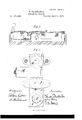
- Figure 1 is a plan view, with some of the planks of the platform removed to show the peculiarities below.
- Fig. 2 is a cross-section on the line S S in Fig. l; and
- Fig. 3 is a plan view, showing certain parts on a larger scale.
- A are the fixed parts.
- B B are the knifeedges by which the main levers are slung up by suitable links, and
- O O are the knife-edges to which the platform W is suspended by suitable links, all as in my patent of May 11 aforesaid.
- the several knife-edges should be all parallel to each other. They are set in short rigidly united to a piece of gas-pipe, E, ofsufficient length to connect the two parts for the wide end of a main lever.
- G G are long arms, preferably tapering, and formed with broad flanges g, which match fairly and firmly against corresponding flanges d on the parts D, and are rigidly bolted thereto by fastenings H.
- One or more bolts, I join the ends of the arms G G.
- the lateral lever M turning on a suitable knife-edge, is formed with a T end, M M carrying conical points at m.
- Yokes J communicate the strain from corresponding points on the ends of the triangular main lever
- the improved construction has few bearings,and is easy to construct and keep in order. It allows for the motion of the platform and its supporting-levers in all directions, either due to a temporary swinging or to a permanent settling or disturbance of position.
- the mechanism for a large scale can be shipped in one box of moderate size.
- each lever may have knife-edges, taking care to employ links and connections which will allow slight swinging movements in all directions.
- Each cross-connection E may, instead of a hollow pipe, be a solid bar; or it may, if preferred, be a connection of cast-iron extended across.
- the invention may be worked with advantage with only the features above described. But I have added a feature very important in practice as a means for insuring the correct horizontal position of the several levers. I
- T- ended lateral lever with two projections, M M, one on each side of its central knife-edge, the upper surfaces of both being plane.
- the lever M may be set horizontal, and all the other parts adjusted to stand in corresponding positions.
Landscapes
- Physics & Mathematics (AREA)
- General Physics & Mathematics (AREA)
- Farming Of Fish And Shellfish (AREA)
Description
2 Sheets-$iieet 1.
T. FAIRBANKS. wmenms SCALES.
Patented April 4,, 1876.
746512 e55 Cfi: %7 Inventor.-
N. PETERS, PHOTO-LITHOGRAPNER, WASHINGTON, D, C,
2 Sheets-Sheet 2.
T. FAIRBANKS.
' WEIGHING SCALES.
No.175,596. Patented April 4, 1876-.
In 1 611 Z01" gmmc stout pieces D, which are cast on or otherwise UNITED STATES THADDEUS FAIRBANKS, or
PATENT OFFICE.
ST. J OHN SBURY, VERMONT.
IMPROVEMENT IN WEIGHING-SCALES.
Specification forming part of Letters Patent No. 175.596., dated April 4, 1876 application filed February 4, 1876.
To all whom it may concern:
Be it known that I, THADDEUS FAIRBANKS, of St. Johnsbury, Caledonia county, in the State of Vermont, have invented certain Improvements relating to Weighing-Scales, of which the following is a specification:
The patent to me dated May 11, 1875, describes the long triangular levers as cast each in a single piece. I have devised a mode of construction which is staunch and reliable, and allows each lever, made in separate parts, to be transported with greater facility and less cost, and be put together at the place where the scale is wanted. I have also improved the mechanism by employing a train of lateral levers with a T end, receiving separate yokes or links from the two main levers.
Thefollowing is a description of what I consider the best means of carrying out the invention.
The accompanying drawings form a part of this specification.
Figure 1 is a plan view, with some of the planks of the platform removed to show the peculiarities below. Fig. 2 is a cross-section on the line S S in Fig. l; and Fig. 3 is a plan view, showing certain parts on a larger scale.
Similarletters of reference indicate like parts in all the figures.
A are the fixed parts. B B are the knifeedges by which the main levers are slung up by suitable links, and O O are the knife-edges to which the platform W is suspended by suitable links, all as in my patent of May 11 aforesaid. The several knife-edges should be all parallel to each other. They are set in short rigidly united to a piece of gas-pipe, E, ofsufficient length to connect the two parts for the wide end of a main lever. G G are long arms, preferably tapering, and formed with broad flanges g, which match fairly and firmly against corresponding flanges d on the parts D, and are rigidly bolted thereto by fastenings H. One or more bolts, I, join the ends of the arms G G. The lateral lever M, turning on a suitable knife-edge, is formed with a T end, M M carrying conical points at m. Yokes J communicate the strain from corresponding points on the ends of the triangular main levers G G.
The improved construction has few bearings,and is easy to construct and keep in order. It allows for the motion of the platform and its supporting-levers in all directions, either due to a temporary swinging or to a permanent settling or disturbance of position. The mechanism for a large scale can be shipped in one box of moderate size.
Some of the details may be modified without defeating the objects of the invention. Thus, instead of conical points m, with corresponding conical points on the levers below, each lever may have knife-edges, taking care to employ links and connections which will allow slight swinging movements in all directions. Each cross-connection E may, instead of a hollow pipe, be a solid bar; or it may, if preferred, be a connection of cast-iron extended across.
The invention may be worked with advantage with only the features above described. But I have added a feature very important in practice as a means for insuring the correct horizontal position of the several levers. I
form the T- ended lateral lever with two projections, M M, one on each side of its central knife-edge, the upper surfaces of both being plane. Laying an ordinary level on these projections M M, the lever M may be set horizontal, and all the other parts adjusted to stand in corresponding positions. These projections M M, formed in the casting, and holding their upper faces in the same plane each with the other, the plane being sufliciently above the apex of the center of the lever to hold the level entirely clear thereof, constitute an extremely simple, but highly ef ficient, aid to overcoming one of the greatest difliculties in setting up scales of this class.
Some of the advantages due to certain features of the invention may be separately enumerated as follows: First, by reason of the fact that the main triangular lever is made in pieces with fastenings, as shown, I am able to ship the mechanism for a large scale in a box of moderate size, and with certainty and dispatch put the parts in firm and rigid connection to form a reliable scale. Second, by reason of the separate vyokes J J, suspending the main levers D E G independently to the lateral lever, in connection with the branched orT-ended construction of the latter, as shown by M M M I am able to allow one end of the platform to vibrate or swing without the other, or to allow the platform to twist in every direction, within moderate limits, with out disturbing the relations of the connections. Third, by reason of the flat-topped projections M M on one side and the other of the center of the lever M, I ani able to conveniently determine an exact level position for this lever by an ordinary mechanics instrument, and can then from that find the right positions for all the connected parts With certainty and with little labor.
I claim as my invention- 1. The main triangular levers, formed with separate arms, rigidly secured together and to the other parts by the fastenings H I, as and for the purposes specified.
2. The combination of the T- ended lateral lever M M M with suitable main levers, transferring the weight to theT-ended lever through separate yokes or links J J, substantially in the manner and for the purposes herein set forth.
3. The projections M M on opposite sides of the central knife-edge of the lateral lever M, adapted to receive and hold a leveling-instrument in a plane above, but parallel to, the bearings of the lever, as and for the purposes herein specified.
In testimony whereof l have hereunto set my hand this 1st day of February, 1876, in the presence of two subscribing witnesses.
THADDEUS FAIRBANKS.
Witnesses:
ELIJAH D. BLODGETT, PERLEY F. HAZEN.
Publications (1)
| Publication Number | Publication Date |
|---|---|
| US175596A true US175596A (en) | 1876-04-04 |
Family
ID=2245003
Family Applications (1)
| Application Number | Title | Priority Date | Filing Date |
|---|---|---|---|
| US175596D Expired - Lifetime US175596A (en) | Improvement in weighing-scales |
Country Status (1)
| Country | Link |
|---|---|
| US (1) | US175596A (en) |
-
0
- US US175596D patent/US175596A/en not_active Expired - Lifetime
Similar Documents
| Publication | Publication Date | Title |
|---|---|---|
| US163060A (en) | Improvement in weighing-scales | |
| US57641A (en) | Improvement in weigh-lock scales | |
| US438248A (en) | stewart | |
| US181099A (en) | Improvement in weighing-scales | |
| US777012A (en) | Weighing-scale. | |
| US441433A (en) | Means for attaching casters or wheels to scales or other articles | |
| US620606A (en) | Scale-beam attachment | |
| US554983A (en) | Wagon-scale | |
| USRE6888E (en) | Improvement in platform-scales | |
| US151689A (en) | Improvement in scale-beams | |
| US322146A (en) | allen | |
| US971757A (en) | Corner-bracket for pitless wagon-scales. | |
| US175597A (en) | Improvement in weighing-scale beams | |
| US168629A (en) | Improvement in railroad-track scales | |
| US416399A (en) | Weighing-scales | |
| US6097A (en) | Level-scale for canals | |
| US417700A (en) | Weighing-scale attachment | |
| US415221A (en) | Weighing-scales | |
| US173669A (en) | Improvement in weighing apparatus | |
| US993906A (en) | Weighing-scale. | |
| US413572A (en) | steedman | |
| US359636A (en) | Railway track-scale | |
| US553978A (en) | Scale | |
| US524271A (en) | Thirds to george light and james j | |
| US441827A (en) | Platform-scale |