US1754399A - Utilization of the force of gravity and relative apparatus - Google Patents
Utilization of the force of gravity and relative apparatus Download PDFInfo
- Publication number
- US1754399A US1754399A US150335A US15033526A US1754399A US 1754399 A US1754399 A US 1754399A US 150335 A US150335 A US 150335A US 15033526 A US15033526 A US 15033526A US 1754399 A US1754399 A US 1754399A
- Authority
- US
- United States
- Prior art keywords
- piston
- cylinder
- container
- valve
- cable
- Prior art date
- Legal status (The legal status is an assumption and is not a legal conclusion. Google has not performed a legal analysis and makes no representation as to the accuracy of the status listed.)
- Expired - Lifetime
Links
Images

Classifications
-
- F—MECHANICAL ENGINEERING; LIGHTING; HEATING; WEAPONS; BLASTING
- F03—MACHINES OR ENGINES FOR LIQUIDS; WIND, SPRING, OR WEIGHT MOTORS; PRODUCING MECHANICAL POWER OR A REACTIVE PROPULSIVE THRUST, NOT OTHERWISE PROVIDED FOR
- F03G—SPRING, WEIGHT, INERTIA OR LIKE MOTORS; MECHANICAL-POWER PRODUCING DEVICES OR MECHANISMS, NOT OTHERWISE PROVIDED FOR OR USING ENERGY SOURCES NOT OTHERWISE PROVIDED FOR
- F03G3/00—Other motors, e.g. gravity or inertia motors
Description
April 1930- e. PASCUCCI 1,754,399
' UTILIZATION OF THE FORCE OF GRAVITY AND RELATIVE APPARATUS Filed Nov. 25, 1926 4 Sheets-Sheet l GIUSEPPE PASCUCC! G. PASCUCCI April 15, 1930.
UTILIZATION OF THE FORCE OF GRAVITY AND RELATIVE APPARATUS Filed Nov. 23, 1926 4- Sheets-Sheet 2 gvnnntc a G IUSEPPE PASCUCCI Gnome April 15, 1930. e. PASCUCCI 1,754,399
UTILIZATION OF FORCE OF GRAVITY AND RELATIVE XPPARATUS Filed NOV. 23, 1926 '4 Sheets-Sheet 3 gwuwnoz GIUSEPPE PASCUCCI April 15, 1930. s. PAscucc| V 1,754,399
I UTILIZATION OF THE FORQE 0F GRAVITY AND RELATIVE APPARATUS Filed Nov. 23. 1926 4 Sheets-Sheet 4 GIUSEPPE PAscuccl Patented Apr. 15, 1930 UNITE STATESP mew: Fer
GIUSEPPE PASCUCCI, F .GENOA, ITALY UTILIZA'DIQLLOE THE FORCE orennvmy AND RELATIVE APPARATUS,
Application filed November 23,1926, Serial No. 150,335, and in Italy January 20, 1926.
This invention relates-to the utilization of the forces of gravity for the production or" motive power and more particularly to an apparatus adapted to transform potential static energy into kinetic energy and potential dynamic energy.
The principal object of this inventon is the provision of a novel apparatus for transforming energy Other objects of the invention are the provisio'nof an apparatus for transforming the potential static energy of a solid mass into kinetic and potential dynamic energ ,(2) an apparatus for transforming the potential static energy of a liquid mass into kinetic and potential dynamic energy, (3) an apparatus for transforming the potentialstaticenergy of a solid or, liquid mass into kinetic and potentialdynamic energy through the medium of a fluid, a funnel-shaped hopper to increase the efficiency of the above mentioned apparatus and (5) an apparatus of the type described for raisingwater froma sea, lake or river. Still otheriobjects of the invention which are in herent therein will beobvious from the following description.
These objects maybe realized by the use of my apparatus which comprises generally a pulley supporting a mass composed of a. container and its contents,
gravity upon the mass will cause it to fall and develop useful energy atthe axle, of the pul-.
The action. of
ley. The container is then emptied and returned toits original position, refilled and the cycle repeated. The accompanying drawings illustrate va-i rious modifications of my invention, in which similar reference characters designate. sinn ilar parts and wherein:
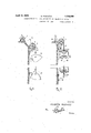
Figure 1 is an elevation of anapparatus according to the present invention, also showingthe bucket container in discharging position.
Figures 2, 3,4 and 5 are elevations, partly in vertical section, of modifications of the apparatus shown in Figure Figurefi is an elevation, showing the con struction modified to adapt it to elevating water from the sea,-river or other source. Figures 7 and 8 are vertical -sections showinvention.
The] simplest form of my invention (see Figure 1) has a dump cart 1 positioned above a loadlng hopper 2,,conducting the weighting material into the bucket container The bucket container 3 is suspended by means of, 6
a cable 4 which is wound on a pulley 5, said pulley havinganaxle 6 which is rotatably supported in fixed bearings. 6; The bucket. container?) has integral therewith a hook? which engages a stop 8 to dump the bucket 651*;
container in the direction of arrow: 9 when "the same ,i has descended vertically .a predee.
termined distance, The cablet is'attached to the bucket container 3 at points above the center of gravity thereof so that there will be no tendency to overturn the same, during filling.
The potential statlcenergy so, transformed into klnetlc energy may be accumulated as potential .dynamic energy and a part, thereof used to raise the bucket container 3 to its fill ing position by any convenient-means. This construction is especially adaptable to the use ofa solid weighting materiah such'as dirt, l, stones, etc.
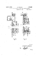
The apparatus of the inventionis adaptable to the ,use ofrwater as a weighting materal (see Figure 2) byhaving a source of water supply l0,fill a container 11 which is'supported atpoints above its center of gravity by means of a cable 4, which is wound on, a pulley 5 having an axle 6 supported in suitable bearing 6'2 Container 11 has positioned; in the bottom thereof a valve 12 which hasa rod l2extendin therethroiwh and is uided by an arborll integral with the. bottom of container 11. A stop 13 is positioned so that, it engages rod, l2and opens the valve 12in the direction of the arrow 1 y against the ac tion of a spring l2whichjencircles rod '12 between valve 12 and arbor 11', thereby effecting the discharge of the water from container 11.
The energy 7 developed by-the descent .of
container 11 may be-accumulated, as before,
and a part thereof used for the elevation of the empty container to the filling position.
The construction of Flgure 1 may be modified as shown in Figure 3 so that the weight- 5 ing material acts to compress a fluid, air or 2' and is closed by a bottom 23. Within cylinder 14 is a piston 17 which has aflixed there on said bucket container 15 which is also attached to acable 4, which is wound upon a pulley having an axle 6 rotating in a set of bearings.
:0 Cylinder 14 is provided near its lower end with an outlet pipe 18 which may be provided with a non-return valve, and the length of arm 21 is such that outlet pipe 18 is closed when flap valve 19 is opened.
The bottom 23 of the cylinder is also provided with an opening 25 and a flap valve 25', which is adapted to open and close simultaneously with flap valve 19 by any convenient means. Flap valve 19 is positively maintained in close position by means of a latch 20 (see Fig. 3) pivotally mounted at 24. Latch 20 is integral with arm 21 which is rotated about the point 24 and is disengaged when piston 17 reaches its lower position. Flap valve 19 is then opened because of the weight of the material above it. Arm 21 engages an inclined stop 21 (see Fig. 6) to cause rotation thereof when piston 17 descends.
After the discharge of the weighting material the piston 17 will be raised and arm 21 will return to normal position thereby locking the flap valves 19 and 25' in closed position.
The apparatus of Figure 3 may be modified to adapt it to the use of a low density liquid as the weighting material (see Figure 4). The cylinder 14 has the inlet pipe 26 and outlet pipe 18, opened and closed depending on the position of piston 17, and also a second outlet pipe 32 with a control valve 33 positioned in the bottom 23' thereof. Said valve 33 may be operated manually or automatically by means actuated by the piston 17. Because of the low viscosity of the weighting material a valve 27 is used to close the port 19' in piston 17, this valve is guided vertically by means of a plurality of stems 28 integral therewith and passing through the piston 17 Suitable springs 30 surround stems 28 and are retained in position by heads 29 on the ends of said stems 28. A stop post 31 positioned on the bottom of the cylinder abuts valve 27 when piston 17 is lowered.
The cable 4, which is wound on pulley 5, is attached to the top of said valve 27. Filling the bucket container 15 will cause piston 17 to descend, thereby compressing the fluid in space 16 and forcing it through pipe 18. As the piston 17 approaches the bottom 23 of the cylinder, stop post 31 will abut valve 27 overcome the resiliency of springs 30 and raise valve 27, thereby allowing the low viscosity weighting material to discharge through port 19', valve 33 and pipe 32. Piston 17 and bucket container 15 are raised to filling position in the manner described in connection with Figure 3.
Figure 5 shows a construction somewhat similar to that of Figure 4 adapted to be used when it is necessary to obtain a higher liquid pressure on piston 17. To this end the bucket container 15 is dispensed with and the space over piston 17 is filled with the weighting material. A cover 34 on cylinder 14 supports a pipe 35 having a funnel-shaped upper end 36, the arrangement being such that the pressure of liquid on the piston is increased as indicated by the line 72,.
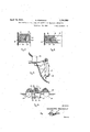
In Figure 6 a modification is shown which 3 is especially adaptable to raising water from a sea, lake, river, etc., for irrigation or other purposes. A cylinder 37, suitably suspended in the water 38 by means not illustrated, is
provided with a piston 39 of the type illus- 1.:
trated in Figure 3, and has pivoted on the bottom thereof an arm 21, which will release the valve in said piston 39 when said arm 21 engages a stop 21 attached to the cylinder.
A bucket 40 is disposed on top of piston 39, 1
and has the cable 50 attached thereto. Cable 50 is wound on pulley 5 in the manner previously described.
Near the bottom of the cylinder is a pipe connection 51 to which is attached a non- .i-i
return valve 52 which communicates with a riser 53. The bottom 54 of the cylinder is hinged at 55 and is provided with a rigid arm 56 to which a cable 59 is connected. A hooked catch 57, hinged at 58 and normally retained 1' tightly overcoming The valve inthe piston will 'be opened as above described by means of engagement of armBl with a-stop 21. Th-e'hooked catch 57 will then be rotated by means of cable 60 so thatthe bottom 54 willbe opened in the direction of arrow 62 by theweight of the mass in cylinder 40 which will be discharged therethrough. .Thebottom 54 and the arm 56' take the positionsshown in broken lines at 54 and 56 respectively. Immediately after the discharge of the weighting material the valve in piston 39 will be closed and the hooked catch 57 will return to its closingposition, thetension on cable 60 having been 1 released, to retain the bottom 54 closed. Bottom 54=is brought to its closed'position by means of tension on cable 59 raising arm-56. The bucket 40 and piston 39'are now raised to the filling position, the weighting material will again enter bucket 40 and the cycle will be repeated.
It is extremely desirable in devices which rely upon the action of a piston, to provide a means which will cause said piston to fit as as possible against the walls of the cylinder. It is also desirable to relieve the pressure between the piston and the cylinder wall during the return stroke of said piston in order to reduce the friction losses to a minimum. To this end the pistonillustrated in the aforementioned devices is provided with an elastic piston ring 70 (see Figure 7) contained within a groove on the periphery of the piston 72. Said piston is further provided with a right angle channel 72 the horizontal. leg of which contains a spring 75 act ing on a plunger 75 which engages piston ring 70.
The above mentioned objects, namely a tight fit on the down stroke and loose fit on the up stroke, will be obtained by such an arrangement inasmuch as the fluid which is above piston 72 causing the down stroke thereof will also exert a pressure on plunger 7 5' the action of spring 75 forcing piston ring 70 to make a tight fit with the cylinder wall. Since the fluid above piston 7 2 is discharged at the end of the down stroke the pressure on plunger 75 will be removed and spring 75 will act to retract piston ring 70 to reduce to a minimum the friction with the wall of cylinder 14: during the up stroke.
VJ hen the weighting material lacks suflicient flowing properties this device for afford ing a tight fit of piston ring 7 must be modified (see Figure 8). In this modification piston ring 70 is disposed in a groove on the periphery of piston 72 above which there is a solid or highly viscous material as at 71. Since the transmission of pressure through the fluid will not be as eflicient the resilient spring 75 retracting plunger 75 must be actuated by means of valve 73. Hence when valve 7 3 is in closed position during the down a? stroke of the piston, plunger 75 will be inthe bottomof closed, a piston within said cylinder, a piston forced to the left (see Figure 8) ti and piston ring 7 0 will betightlyheldagainstthewall of cylinder 14. Upon discharge of the weighting material valve 7 8 will be opened andpressure on plunger 75 will be relieved allowing spring 75'to retract said plunger and said 1 piston w ring with the wall ofthe cylinder.
F igurei) illustrates schematically an installationin which the apparatus shownin Figures'3, 4 01" may be incorporated. Inthis installation the pipe 18 which leads from the lower portion of cylinder 14 is shown conducting the compressed fluid therefrom to tank 76 inwhich the same is stored as potential dynamic energy.
Figure illustrates the manner in which a a device of the character shown in Figure 1 can be adapted to use on a barge 63 which is supported by: ponto-ons 64; In this modificaionthe element8of Figure l is replaced by the cable 6O'whichis wound on a drum 66,this cable will have predetermined length depending on thevertical displacement of the bucket 67. The bottom 54 of bucket 67 is hinged thereto in a manner similar to that shownin Figure 6 and is brought into closed position by means of an arm 56 integral there with and raised by a means ofa cable 59 which is wound on a drum 69; The hinged arm 57 pivoted aboutpoint 58 engages the bottom 54 to hold the same in closed position until ca ble 60 becomes taught to= disengagesaid arm 57 from the bottom. The bucket'67 is suspended as in the other modifications'by means of a cable iwhioh is wound up on pulley5 havingsyan= axle 6 which-rotates in a set of'fixed bearings 6.
It is evident-that numerous slight changesmay be made in the general form and'arran-gement of the severalparts herein shown and described without departing fromthe spirit and scope of this'invention, and hence said invention is not to be construedas limited to the precise details of construction shown anddescribed, but these illustrations are-to be consi dered merely in an illustrative sense.
Having fully described my invention, what 70 from-tight engagement I claim 'as new, and desireto protect 'by Let- I ters Patent is:
1. An apparatus fora the transformation of mechanical energy comprising a cylinder having a bottom, a cylinder discharge means said cylinder normally discharge means therein also normally closed, a. pulleyhaving *a' cable capableof being wound thereon, said cable being attachedito said container to intermittently raise the same, fluid inlet means in i said cylinder below said "piston in raised position, compressed fluid outlet means and means for opening said piston discharge means and said cylinder discharge means when said pistonis in lower mostposition.
2. An apparatus for the transformation of mechanical energy comprising a cylinder having a bottom, a cylinder discharge means in the bottom of said cylinder normally 5 closed, a cover having a funnel-shaped extension positioned on the top of said cylinder, a piston within said cylinder, a piston discharge means therein also normally closed, a pulley having a cable capable of being wound thereon, said cable being attached to said container to intermittently raise the same, fluid inlet means in said cylinder below said piston in raised position, compressed fluid outlet means and means for opening said piston discharge means and said cylinder discharge means when said piston is in lowermost position.
3. An apparatus for the transformation of mechanical energy comprising a cylinder having a bottom, a cylinder discharge means in the bottom of said cylinder normallyclosed, a piston within said cylinder, a piston discharge means therein also normally closed, a container positioned above said piston, a
pulley having a cable wound thereon, said cable being attached to said container to intermittentlyraise the same, fluid inlet means in said cylinder below said piston in raised position, compressed fluid outlet, means and means for opening said piston discharge and said cylinder discharge means when said piston is in lowermost position.
4. An apparatus for the transformation of mechanical energy comprising a cylinder having a bottom, a cylinder discharge means in the bottom of said cylinder, a piston within said cylinder, a piston discharge means therein also normally closed, a rotating latch means maintaining said piston discharge means in closed position, a pulley having a cable wound thereon,v said cable being attached to said container to intermittently raise the same, fluid inlet means in said cylinder below said piston in raised position,
compressed fluid outlet means, disengaging means intermittently engaging said rotating latch means to unlach the same thereby opening said piston discharge means and means for opening said cylinder discharge means.
5. An apparatus for the transformation of mechanical energy comprising a cylinder having a bottom, a cylinder discharge means in the bottom of said cylinder normally closed, a piston within said cylinder, a piston discharge means therein also normally closed,
a pulley having a cable wound thereon, said cable being attached to said container to intermittently raise the same, fluid inlet means in said cylinder below said piston in raised position, compressed fluid outlet means above said piston in lowermost position and means for opening said piston discharge and said cylinder discharge means when said piston is in lowermost position.
6. An apparatus for the transformation of mechanical energy comprising a cylinder having a bottom, a cylinder discharge means in the bottom of said cylinder normally closed, a piston within said cylinder, a piston discharge means therein also normally closed, a piston ring in the periphery of said piston exerting a pressure on the wall of said cylinder during descent thereof and retracted by a spring during the ascent thereof, a pulley having a cable wound thereon, said cable being attached to said container to intermittently raise the same, fluid inlet means in said cylinder below said piston in raised position, compressed fluid outlet means and means for opening said piston discharge and said cylinder discharge means when said piston is in lowermost position.
GIUSEPPE PASOUCCI.
Applications Claiming Priority (1)
| Application Number | Priority Date | Filing Date | Title |
|---|---|---|---|
| IT1754399X | 1926-01-20 |
Publications (1)
| Publication Number | Publication Date |
|---|---|
| US1754399A true US1754399A (en) | 1930-04-15 |
Family
ID=11434581
Family Applications (1)
| Application Number | Title | Priority Date | Filing Date |
|---|---|---|---|
| US150335A Expired - Lifetime US1754399A (en) | 1926-01-20 | 1926-11-23 | Utilization of the force of gravity and relative apparatus |
Country Status (1)
| Country | Link |
|---|---|
| US (1) | US1754399A (en) |
Cited By (1)
| Publication number | Priority date | Publication date | Assignee | Title |
|---|---|---|---|---|
| US3994629A (en) * | 1974-11-18 | 1976-11-30 | Tah Sun Lin | Mechanism for tapping the surf energy |
-
1926
- 1926-11-23 US US150335A patent/US1754399A/en not_active Expired - Lifetime
Cited By (1)
| Publication number | Priority date | Publication date | Assignee | Title |
|---|---|---|---|---|
| US3994629A (en) * | 1974-11-18 | 1976-11-30 | Tah Sun Lin | Mechanism for tapping the surf energy |
Similar Documents
| Publication | Publication Date | Title |
|---|---|---|
| JPS6397877A (en) | Wave energy extractor and method | |
| EP0006868A1 (en) | Ocean tide energy converter | |
| CN207268681U (en) | Pouring pile hole bottom slurry sampler | |
| US3952517A (en) | Buoyant ram motor and pumping system | |
| US1105249A (en) | Tide-motor. | |
| US3828857A (en) | Apparatus for filling and emptying containers for use in firefighting | |
| CN203845278U (en) | Multi-hydraulic-cylinder lifting type buried garbage can | |
| US1754399A (en) | Utilization of the force of gravity and relative apparatus | |
| CN110282299A (en) | A kind of three cylinder vertical garbage compression set of high efficiency | |
| TW201704633A (en) | Tidal power generation system | |
| US2239064A (en) | Water motor | |
| US2129292A (en) | Pumping system | |
| FR2654409A1 (en) | Device making it possible to raise heavy and bulky objects from the bottom of water | |
| CN110342161A (en) | Mobile garbage compressor station and its control method | |
| CN207130670U (en) | A kind of irrigating apparatus for simulating tidal bore | |
| CN214731506U (en) | Petroleum barrel with liquid level display function | |
| US1868924A (en) | Fuel charging device for gas generators | |
| US2668918A (en) | Tide-operated power plant | |
| CN209383362U (en) | A kind of filling oil machine | |
| US2536475A (en) | Device for pumping out floats | |
| CN210479667U (en) | Hydraulic material drawing machine for mud storage groove | |
| US1064420A (en) | Well-bucket. | |
| US1073682A (en) | Wave-motor. | |
| US1903633A (en) | Gate | |
| CN205397165U (en) | Rubbish station device of locking a door |