US1754360A - Automobile theft-signal switch - Google Patents
Automobile theft-signal switch Download PDFInfo
- Publication number
- US1754360A US1754360A US88003A US8800326A US1754360A US 1754360 A US1754360 A US 1754360A US 88003 A US88003 A US 88003A US 8800326 A US8800326 A US 8800326A US 1754360 A US1754360 A US 1754360A
- Authority
- US
- United States
- Prior art keywords
- housing
- wire
- vehicle
- pendulum
- switch
- Prior art date
- Legal status (The legal status is an assumption and is not a legal conclusion. Google has not performed a legal analysis and makes no representation as to the accuracy of the status listed.)
- Expired - Lifetime
Links
- 239000004020 conductor Substances 0.000 description 1
- 238000010586 diagram Methods 0.000 description 1
- 239000012634 fragment Substances 0.000 description 1
- 230000005484 gravity Effects 0.000 description 1
Images
Classifications
-
- B—PERFORMING OPERATIONS; TRANSPORTING
- B60—VEHICLES IN GENERAL
- B60R—VEHICLES, VEHICLE FITTINGS, OR VEHICLE PARTS, NOT OTHERWISE PROVIDED FOR
- B60R25/00—Fittings or systems for preventing or indicating unauthorised use or theft of vehicles
- B60R25/01—Fittings or systems for preventing or indicating unauthorised use or theft of vehicles operating on vehicle systems or fittings, e.g. on doors, seats or windscreens
- B60R25/04—Fittings or systems for preventing or indicating unauthorised use or theft of vehicles operating on vehicle systems or fittings, e.g. on doors, seats or windscreens operating on the propulsion system, e.g. engine or drive motor
-
- Y—GENERAL TAGGING OF NEW TECHNOLOGICAL DEVELOPMENTS; GENERAL TAGGING OF CROSS-SECTIONAL TECHNOLOGIES SPANNING OVER SEVERAL SECTIONS OF THE IPC; TECHNICAL SUBJECTS COVERED BY FORMER USPC CROSS-REFERENCE ART COLLECTIONS [XRACs] AND DIGESTS
- Y10—TECHNICAL SUBJECTS COVERED BY FORMER USPC
- Y10S—TECHNICAL SUBJECTS COVERED BY FORMER USPC CROSS-REFERENCE ART COLLECTIONS [XRACs] AND DIGESTS
- Y10S200/00—Electricity: circuit makers and breakers
- Y10S200/12—Burglar screens
Landscapes
- Engineering & Computer Science (AREA)
- Mechanical Engineering (AREA)
- Burglar Alarm Systems (AREA)
Description
April 15,1930. F. H. HENDRICKS AUTOMOBILE THEFT SIGNAL SWITCH Filed Feb. 13 1926 INVENTOR flea H. fie/1061268.
Patented Apr. 15, 1930 UNITED STATES FRED H. HENDRICKS, F SEATTLE, WASHINGTON AUTOMOBILE THEFT-SIGNAL SWITCH Application filed February My invention relates to improvements in theft signals for the use on motor vehicles and the object of my invention is to provide a theft signal for use on a motor vehicle that I may be set so that it will sound an alarm if the vehicle-is tampered with by unauthorized persons.
Another object is to provide a theft signal that is operated electrically and that may be set so that it will be sounded by any substantial movement of the body of a motor vehicle. such, for instance as might occur if an unauthorized person attempted to start the motor of the vehicle.
Another object is to provide a theft signal of this class that is arranged to hang vertically at all times when the vehicle body on which it is carried is at rest regardless of the position of said vehicle body and which will only be disturbed by shaking, jolting or vibration of the vehicle body.
A further obj ectis to provide a theft signal of this nature having a secret, or lock controlled, switch connected therewith by which said theft signal may be disconnected and rendered inoperative by a person authorized to use the vehicle and to further provide a theft signal in which the circuit that sounds the warning is completed by means of a gravity operated pendulum device that responds very readily to vibration or shaking of the vehicle body.
Other and more specific objects will be apparent from the following description taken 35 in connection with the accompanying drawings.
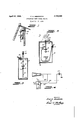
In the drawings, Figure 1 is a view in side elevation of a theft signal constructed in accordance with my invention, showing in cross section a fragment of a motor vehicle on which the theft signal is installed.
Fig. 2 is a sectional view on a larger scale on broken line 2-2 of Fig. 1, showing the inside mechanism of said theft signal in elevation.
Fig. 3 is a similar view on broken line 33 of Fig. 2.
Fig. 4 is a diagram showing the electrical connections to the signal.
m Referring to the drawings, throughout 13, 1926. Serial 1%. 88,003.
which like reference numerals designate like parts, 6 is a rectangular housing having at its upper end an extension 7 provided with a hole 8 adapted to fit over a pivot bolt 9 that is secured in a suitable and preferably inconspicuous location to the frame or dash 10 of a motor vehicle.
A light spring 19 on the bolt 9 bears lightly against the extension 7 and prevents the housing from rattling but does notinterfere with the free swinging movement of said housing.
A binding post 11 extends through one side of the housing 6 and is secured within the housing, to a relatively fine spring wire 12 that extends downwardly thence across said housing, thence upwardly to a point about half way between the top and bottom of the housing and terminates in a horizontally disposed loop 13. The wire 12' is relatively long and, by reason of the manner in which it is bent around is very flexible and sensitive to movement.
Another binding post 14 extends downwardly through the top of the housing 6 and is electrically and mechanically connected by a clip 15 with a wire pendulum 16 that swings freely from the clip 15 and passes downwardly through the loop 13'of the wire 12. A weight 17 is provided on the bottom end of the Wire pendulum 16.
One binding post, as binding post 1 1 is connected by wire 20 with one terminal of the horn 21 of the motor vehicle, the other terminal of said horn usually being grounded. Any electrically operated audible device may be substituted for the horn 2. The other binding post 11 is connected by wire 22 with one terminal of a switch 23 and the other terminal of the switch 23 is connected with any suitable circuit wire of the motor vehicle that connects with a battery 24. The switch 23 may be either a secret or concealed switch or it may be. a lock controlled switch. v
In the operation of this theft signal, when a vehicle on which the device is installed is stopped the housing 6 will always hang in a vertical position and the pedulum wire will also hang in a vertical position and pass through the center of the loop 13 without touching said loop.
If the vehicle is to be left standing or is parked the driver may close the switch 23 thus making it possible for the pendulum 16 by touching the wire 12 to close the circuit to the horn and sound said horn. If, when the switch 23 is thus closed, the vehicle is tampered with, as by a person trying to start the motor for the purpose of stealing the vehicle, the movement and vibrations i1nparted to the vehicle body will cause the pendulum wire 16 to swing against, and make contact with, the wire 12 thus momentarily closing the circuit to the horn and sounding said horn. As long as the unauthorized person continues to tamper with the vehicle the horn will continue to be sounded intermittently thus Warning others in the vicinity that the vehicle is being tampered with. The owner or authorized driver of the vehicle will open the switch 23 before making any attempt to start the vehicle and thus avoid sounding the horn, it being apparent that the pendulum wire 16 can not complete a circuit to the horn when the switch 23 is open.
The wire 12 is very flexible and sensitive and yields easily to t e pressure of the pendulum wire so that electrical contact will be only momentary each time and will be quickly broken before the wire 12 and the pendulum wire have time to adhere or weld to each other. This mode of operation is also desired in a theft signal, it being desired to sound the horn intermittently instead of continuously.
The foregoing description and accompanying drawings clearly disclose a preferred embodiment of my invention but it will be understood that this disclosure is merely illustrative and that such changes in the device may be resorted to as are within the scope an spirit of the following claims.
I claim:
1. In a theft signal of the class described a housing, means for suspending said housing for swinging movement, a vibratory electrical conductor secured within the upper portion of said housing and extending downwardly along one side, thence across the lower portion, thence upwardly along the other'side, thence inwardly to the central axis of said housing, the end of said inwardly extending ortion having a horizontally disposed loop ormed therein and an electrically conductive suspended pendulum extending through said loop and arranged to make contact with said loop in response to tilting movement of said housing.
2. In a theft signal of the class described, a housing means for suspending said housing where y said housing may swing freely and may normally hang verticall an electrically conductive member of su stantially U shape disposed in said housing and having a horizontal loop formed therein a pendulum hanging from the top of said housing and extending through said 100 and circuit means connected wit said pen ulum and said electrically conductive member res ectively.
3. In a, circuit closer for a t eft signal of the class described, the combination with a motor vehicle, of a housing arranged to be suspended from a part of said vehicle so as to swing freely, a vibrator electrically conductive wire secured wit in said housing and extending first downwardly thence across said housing and thence upwardly and having a horizontally disposed loop formed on its end, a wire pendulum swingingly suspended from the top of said housing and passmg through said loop and arranged to make electrical contact with said loop, a weight on the bottom end of said pendulum and circuit wires connected with said pendulum and said electrically conductive wire.
The foregoing specification signed at Seattle, Washington, this 12th day of January, 1926.
FRED I-I. HENDRICKS.
Priority Applications (1)
| Application Number | Priority Date | Filing Date | Title |
|---|---|---|---|
| US88003A US1754360A (en) | 1926-02-13 | 1926-02-13 | Automobile theft-signal switch |
Applications Claiming Priority (1)
| Application Number | Priority Date | Filing Date | Title |
|---|---|---|---|
| US88003A US1754360A (en) | 1926-02-13 | 1926-02-13 | Automobile theft-signal switch |
Publications (1)
| Publication Number | Publication Date |
|---|---|
| US1754360A true US1754360A (en) | 1930-04-15 |
Family
ID=22208527
Family Applications (1)
| Application Number | Title | Priority Date | Filing Date |
|---|---|---|---|
| US88003A Expired - Lifetime US1754360A (en) | 1926-02-13 | 1926-02-13 | Automobile theft-signal switch |
Country Status (1)
| Country | Link |
|---|---|
| US (1) | US1754360A (en) |
Cited By (8)
| Publication number | Priority date | Publication date | Assignee | Title |
|---|---|---|---|---|
| US2679036A (en) * | 1945-11-09 | 1954-05-18 | Anton Vasek | Fishing line signaling device |
| US2689341A (en) * | 1951-11-08 | 1954-09-14 | Albert W Holst | Safety device for indicating shifting of structures |
| US2729017A (en) * | 1953-09-22 | 1956-01-03 | David W Mealey | Animal exterminating device |
| US2884623A (en) * | 1957-01-31 | 1959-04-28 | Richard C Murphy | Burglar alarm |
| US2984820A (en) * | 1958-01-24 | 1961-05-16 | Franklin B Kennell | Burglar alarm for automobiles |
| US3036296A (en) * | 1958-10-28 | 1962-05-22 | Ernest R Conte | Swimming pool alarm |
| US3064970A (en) * | 1960-03-15 | 1962-11-20 | Alan T Thompson | Novelty shock unit |
| US3150461A (en) * | 1960-11-25 | 1964-09-29 | Grist Franklin James | Toy sounding space helmet |
-
1926
- 1926-02-13 US US88003A patent/US1754360A/en not_active Expired - Lifetime
Cited By (8)
| Publication number | Priority date | Publication date | Assignee | Title |
|---|---|---|---|---|
| US2679036A (en) * | 1945-11-09 | 1954-05-18 | Anton Vasek | Fishing line signaling device |
| US2689341A (en) * | 1951-11-08 | 1954-09-14 | Albert W Holst | Safety device for indicating shifting of structures |
| US2729017A (en) * | 1953-09-22 | 1956-01-03 | David W Mealey | Animal exterminating device |
| US2884623A (en) * | 1957-01-31 | 1959-04-28 | Richard C Murphy | Burglar alarm |
| US2984820A (en) * | 1958-01-24 | 1961-05-16 | Franklin B Kennell | Burglar alarm for automobiles |
| US3036296A (en) * | 1958-10-28 | 1962-05-22 | Ernest R Conte | Swimming pool alarm |
| US3064970A (en) * | 1960-03-15 | 1962-11-20 | Alan T Thompson | Novelty shock unit |
| US3150461A (en) * | 1960-11-25 | 1964-09-29 | Grist Franklin James | Toy sounding space helmet |
Similar Documents
| Publication | Publication Date | Title |
|---|---|---|
| US3422398A (en) | Vehicle solid state alarm system | |
| US2754497A (en) | Device for keeping vehicle operators alert | |
| US1754360A (en) | Automobile theft-signal switch | |
| US5463371A (en) | Window mounted automobile security alarm | |
| US3831163A (en) | Inertia-tilt switch | |
| US3975722A (en) | Protective alarm system | |
| US3828310A (en) | Bicycle theft alarm | |
| US2885504A (en) | Automobile theft alarm | |
| US3939471A (en) | Liquid level tamper alarm | |
| US3562706A (en) | Vehicle self leveling vibration sensitive alarm device | |
| US2402111A (en) | Burglar alarm device for automobiles | |
| US2344854A (en) | Automobile signal | |
| US1568509A (en) | Theft-alarm switch for automobiles | |
| US3997870A (en) | Vehicle anti-theft alarm system | |
| US2014286A (en) | Circuit closing device | |
| US5469141A (en) | Optical motion sensor and method for operating same | |
| US2594676A (en) | Automobile theft alarm | |
| JPH0523428Y2 (en) | ||
| US1902578A (en) | Circuit closer for an automatic signaling device | |
| CN204279355U (en) | A kind of anti-joyride device of former car remote controller | |
| US2407073A (en) | Alarm device for automobiles | |
| US4013995A (en) | Vehicle burglar alarm | |
| US1654931A (en) | Theft-alarm device | |
| US2101429A (en) | Electrical switch | |
| US2448181A (en) | Electric alarm device |