US1754329A - Mining machine - Google Patents
Mining machine Download PDFInfo
- Publication number
- US1754329A US1754329A US157007A US15700726A US1754329A US 1754329 A US1754329 A US 1754329A US 157007 A US157007 A US 157007A US 15700726 A US15700726 A US 15700726A US 1754329 A US1754329 A US 1754329A
- Authority
- US
- United States
- Prior art keywords
- frame
- motor
- machine
- rope
- drums
- Prior art date
- Legal status (The legal status is an assumption and is not a legal conclusion. Google has not performed a legal analysis and makes no representation as to the accuracy of the status listed.)
- Expired - Lifetime
Links
Images

Classifications
-
- E—FIXED CONSTRUCTIONS
- E21—EARTH DRILLING; MINING
- E21C—MINING OR QUARRYING
- E21C29/00—Propulsion of machines for slitting or completely freeing the mineral from the seam
- E21C29/04—Propulsion of machines for slitting or completely freeing the mineral from the seam by cable or chains
- E21C29/06—Propulsion of machines for slitting or completely freeing the mineral from the seam by cable or chains anchored at one or both ends to the mine working face
- E21C29/10—Cable or chain co-operating with a winch or the like on the machine
Definitions
- the principal ⁇ object of my invention is to provide an improved feeding ⁇ mechanism including two rope drums disposed onf horizontal axes on. opposite sides but near the front or cutting end of saidmachine. y Other objects will appear from time to time as: thedescription proceeds.
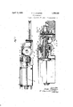
- Figure 1 is a planview of the device emy hodying' my invention with'parts broken away to show the arrangementof the gearing
- Figure 2 is a side elevation ofthe device in.
- Figure 1 1 with some partshrolren away to show the arrangement of the operating levers;
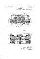
- Figure 3 ⁇ is anenlarged fragmentary side elevation of the deviceshown in Figure 1, a portion of said elevationheing a cross-section talren onr line of.' Figure -1 i
- Figure 4 is a sectional view taken through Figure lon line 4--4 thereof; ⁇ and
- Figure 5 is a sectional, View taken through Figure 1 on line 5 5 thereof..
- the embodiment of myinvention comprises a mining machine 1. having amain frame 2 with ⁇ a cutting element 3 projecting forwardly therefrom, and a dri-ving motor 4 projecting from the rearwardl portion thereof..
- cutting element 3 is preferably provided with an endless chain of the usual type and, projects from. the front end of the machine to out a ⁇ horizontal kerf in the mine wall, ⁇ preferahly adjacent the door as, the ⁇ machine is.
- the motor 4 drives said mechanism through a motor shaftl ⁇ having a pinion 17 at its forward end meshing with and .driving a ⁇ pinion 18 keyed to asleeve 19,' ⁇ Said sleeve islrotatable on a stud 2O fixed against rotation 1n suitable supports on the frame 2. Jaws atthe forward endzof.saidvsleevemesh with gaws 22 on the hub of arloevel ⁇ pinion 25 to rotate said pinion. y ⁇ Saidbevel pinionhas driving connection with. ahevel gear 26 ⁇ which drives a cutter chain27 through ⁇ a clutch 28, shaft 29,. and sprocket 30.4 .y
- Said planetary gearing device is of the same general type as used extensively in mining ⁇ machine gearing, and as herein shown, imparts two frictionall'y controlled speeds to a gear 35 coarialtherewith.
- a suitable friction hand 36 isprovi'ded for said planetary reduction gearing device and is controlled hy a hand wheel 37 at the rearward portion ⁇ of the machine.
- Said hand wheel is threaded to a rod 38 which passes forward through the motor 4 to one arm of alhell cranlrllever 39.
- This hell crank lever is pivoted to the main frame of the machine and the otherarm is pivoted to a rod40which is fastened to a ⁇ movalole end of the friction hand 36.
- a suitable clutch memherwhich is herein shown as a aw clutch 41 provides a means to drive the gear 35 from the planetary reduction gearing device 7 at a plurality of frictionallycontrolled speeds.
- This clutch is operated hy a hand lever 42 at the rear ofthe machine. rlhis hand lever is fastened to the rear end of a rod 43 which entends forwardly through the motor 4 to a crank lever 44 which in ⁇ turn rocks afork 45 attached to a shifting yoke 46 to shift the clutch 41.
- the spur gear 35 meshes with and drives gears 48, 48. ⁇
- These iee gears are keyed to longitudinal shafts 49, 49, on opposite sides of the gear 35.
- the rope drums 5, 5, on the forward portion of the main frame 2 on opposite sides of the cutting element 3 are of the same construction and are both driven from planetar reduction gearing 7 which is rearward of said drums but on a horizontal axis perpendicular with the axes of said drums on the longitudinal center of the main frame 2.
- the gear 35 connected with the planetary reduction gearing 7 drives said drums in op-V osite directions.
- the driving connection to th drums are substantially the same, so
- a worm 50 is integral with the shaft 49 and is forward of the spur gear 48, said worm rotates a worm gear 51 keyed to a transverse shaft 52.
- the shaft 52 is journaled in the main frame 2 and an end portion of said journal box serves as a thrust bearing for the worm gear 51.
- ⁇ A clutch sleeve 55 is feathered to the shaft 52 and has jaws 56 on its inner face engageable with jaws 57 on the inner face of a pinion 58 mounted on the clutch sleeve 55 and free to rotate thereon.
- the outer end kof the pinion 58 has a hub integral therewith, which is journaled in the main frame 2.
- Suitable means are provided to move the clutch sleeve 55 transversely of the frame 2 along the shaft'V 52 to causeV the jaws 56 to engage the jaws 57 on the pinion 58 and drive said pinion through the clutch sleeve 55 and viceversa.
- this shifting means is of a common lever construction operated by a rod 60 at the rear of the machine. The forward end of the rod 60 is pivoted to a crank lever 61 ⁇ which' is keyed to a shaft 62. A fork 63 is also keyed to the shaft 62.
- Said fork is pivoted to a yoke 64'to move the clutch sleeve 55 transversely along the shaft 52 upon movement of the rod 60 and thus engage or disengage the jaws 56 with the jaws 57.
- the pinion 58 mesheswith a spur gear 66 connected to the rope drum 5 which is mounted on a transverse shaft 67.
- the other rope drum on the opposite siderof the machine is also mounted on a similar transverse shaft 67 in ythe same relative position.
- Means are provided for each rope drum to restrain rotation of said drums when either of said drums are disconnected from their driving means, as for instance when either of said drums are used for controlling retardation of the rear end of the machine.
- I provide a common form of friction brake comprising a friction band 7 0 on a flange 71 which is integral with each respective brake drum on the outer end thereof. Said brake is operated by a hand wheel 72 threaded to a rod 73 at the rear of the machine. The rod 73 is fastened to a free end of the brake band so turning of the hand wheel in one direction tightens the brake band and vice versa, to apply or release the brake.
- the arrangement of the rope drums and ropes is such that in the normal cutting position, the rope dru1n ⁇ 5 on the advancing or left yhand side of the machine is connected to the motor 3 to wind in a rope 5a while the opposite drum 5 is connected to the motor 3 to rotate in the same direction.
- the left hand drum has a rope 5b thereon'which is preferably wound on said drum in a direction opposite to that of the rope 5EL on the right hand drum and thus unwinds from the top of said drum simultaneously with and at substantially the same rate of speed as the rate oftakeup on the rope 5a.
- the purpose of the rope 5b during this part of the cutting movement is to Vrestrain the movement ofthe rear end of the machine and maintain the proper angular relation of the cutter bar to the working face.
- the braking means varies the rate of speed at which this retarding rope is un wound from its drum to keep the machine in alignment with the face of the coal.
- the retarding rrope drum however, may be disconnected from the motor when required in maneuvering the machine during the sumping or dragging out operations, or when the cutting is exceptionally hard and the cutting element cannotbe kept in proper alignment to the face of the coal.
- Means are provided for reversing the normal functions of the two drums above deto do this it is only necessary to reverse the direction of rotation of the motor 4. Additional sheaves are also provided on both sides of the machine to allow the ropes to wind in or pay off in the correct position in regards to the machine frame.
- Power may i i V m Referring howto the disposition or discharge of the cuttings brought rearwardly by the cutter chain,- it will be ⁇ understood that thelispeeitic form 'of machine illustrated is of the reversible type,i. e., it is capable of being operated for cutting in either direction. ⁇ Ao
- the cuttings may be brought rearwardly to one-side o-r the other by the cutter chain and will be discharged Athrough an ⁇ opening ("provided for the discharge of said cuttings oneither side of the machine. These openings are 4necessarily small since ⁇ the rope drums, as shown, partially block these spaces,
- Janother advantageous feature of the ma, ⁇ chineabove described is the arrangement of" the feed driving mechanism, wherein the two reduction worm and worm gears 48, 48, are, ⁇ interposed between the single centrally disV posed planetary gear and the respective rope drum. ⁇ on either side of the machine.
- a frame a motor rearward of said frame and connected thereto, slideable on its bottom on amine bottom, a cutter arm projecting forwardly Lfi'om said frame, ieXible feed operating mechanism including awinding drum on either side of said cutter arm and operably connected with said motor to be driven therefrom at a plurality of predetermined speeds,
- a frame a motor rearward of said frame and planetary reductiongear device disiol) connected thereto, slideable on its bottom on i a mine bottom, a cutter arm projecting forwardly of said frame having a cutter chain movable thereon, a driving means for said cutter chain, feed operating mechanism for said mining machine comprising two rope drums on the forward portion of themachine frame, one on each side of the cutter chain driving mechanism and driven by said motor from a common spur gear coaxial and operatively connectibl'e with a lfrictionally controlled planetary reduction gear mechanism coaxial with aportion of said cutter chain driving mechanism rearward of said cutter chain.
- feed operating mechanism for said mining machine comprising two rope drums on the forward portion of the machine frame, one on each side of the cutter chain driving mechanism and driven simultaneously or independently by said motor from a common spur gear coaxial and operatively connectible with a frictionally controlled planetary reduction gear mecha- .nism coaxial with a portion of said cutter chain driving mechanism rearwardly of said cutter cham, and a separate worm and worm gear reduction on each side of said planetary interposed between said planetary gear mechanism and each of said rope drums.
- a frame a chain carrying cutter arm projecting forwardly of said frame, a motor to the rear of said frame, said motor being slideable on its bottom on a mine bottom, a cutter chain driving sprocket adjacent the forward end of said frame operatively connected with said motor, feed operating mechanism comprising two rope drums on transverse axes on opposite'sides of the forward end of said main frame and having an outer periphery extending below the upper portion of said motor, driving connections including a single planetary reduction device on a longitudinal axis between said motor and said drums and beneath the uppermost portion of said motor for driving said drums simultaneously or independently from said motor at a plurality of speeds, said frame being supported for slideable movement on a mine bottom by said motor on its rearward end and a bearing shoe at its forward end, said motor, bearing shoe, frame and rope drumsforming a bottomless cuttings passageway between said bearing shoe and said motor rearwardly of said rope drums, beneath said gearing and opening on each side of said frame.
Description
April 15, 1930. F. A. LINDGREN 1,754g329 MINING MACHINE original'mled Dec. 25, 192e 3 sheets-sheet 1 Aprilv 15, 1930. F. A..| |NDGREN MINING MACHINE Original Filed Dec. 25, 1926 3 Sheets-Shet 2 f 2715091121107* l frank JU @Q2/wilg April 15, 1930. F. A. I xVNDVGREN 1,754,329
I MINING MACHINE Original Filed Dc. 25, 1926 SSheetS-Sheeo I5 .se sa `thin, seams o'ffcoal.`
Patented Apr. 15, 1930 PATE FRANK" n. Linnen-nm or waarnaarsrnirres, IL LrNors, assrenon fro GoonMAN MANUFAGTURINGL contrarier, or carcass, ILM-ners,` a conronnfrron or -ILLI- Nora `ivrrrirind :ernennen Application-filed December 25, `1926, Serial No. 157,007. Renewed September 12, 1929;
`relatesto a machine of this class adapted for operation under very lowhead room, as in The principal` object of my invention is to provide an improved feeding `mechanism including two rope drums disposed onf horizontal axes on. opposite sides but near the front or cutting end of saidmachine. y Other objects will appear from time to time as: thedescription proceeds.
y My invention may he more clearlyl understood by reference to the accompanying drawings., wherein.-
Figure 1 is a planview of the device emy hodying' my invention with'parts broken away to show the arrangementof the gearing Figure 2 is a side elevation ofthe device in. Figure 1 1with some partshrolren away to show the arrangement of the operating levers;
Figure 3` is anenlarged fragmentary side elevation of the deviceshown in Figure 1, a portion of said elevationheing a cross-section talren onr line of.' Figure -1 i Figure 4is a sectional view taken through Figure lon line 4--4 thereof;` and Figure 5 is a sectional, View taken through Figure 1 on line 5 5 thereof..
Referring now in detail to the drawings, the embodiment of myinvention comprises a mining machine 1. having amain frame 2 with` a cutting element 3 projecting forwardly therefrom, and a dri-ving motor 4 projecting from the rearwardl portion thereof.. The
cutting element 3 is preferably provided with an endless chain of the usual type and, projects from. the front end of the machine to out a` horizontal kerf in the mine wall, `preferahly adjacent the door as, the `machine is.
moved `hy draft devices in the well known manner. "Ihe driving motor 4 is attached 1 to therearwardportioniof the main frame 2 and rests on the mine bottom; the height of the `motor shell determining the height of the mining machine.
Referring now to the details of the driving mechanism for the feed and cutting elements, the motor 4 drives said mechanism through a motor shaftl` having a pinion 17 at its forward end meshing with and .driving a` pinion 18 keyed to asleeve 19,'` Said sleeve islrotatable on a stud 2O fixed against rotation 1n suitable supports on the frame 2. Jaws atthe forward endzof.saidvsleevemesh with gaws 22 on the hub of arloevel` pinion 25 to rotate said pinion. y`Saidbevel pinionhas driving connection with. ahevel gear 26 `which drives a cutter chain27 through` a clutch 28, shaft 29,. and sprocket 30.4 .y
Adjacent the rearward end ofsa-i'd hevel pinion and coaxial therewith is the planetary reduction gearing 7 connectible withthe rope drums 5, 5, for driving said rope drums ata plurality of frictionally controlled speeds.
Said planetary gearing device is of the same general type as used extensively in mining` machine gearing, and as herein shown, imparts two frictionall'y controlled speeds to a gear 35 coarialtherewith. A suitable friction hand 36 isprovi'ded for said planetary reduction gearing device and is controlled hy a hand wheel 37 at the rearward portion `of the machine. Said hand wheel is threaded to a rod 38 which passes forward through the motor 4 to one arm of alhell cranlrllever 39. This hell crank lever is pivoted to the main frame of the machine and the otherarm is pivoted to a rod40which is fastened to a `movalole end of the friction hand 36. Tightening of the hand wheel 37 causes the friction hand 36 to apply power to the gear 35 from themotoril at a reduced speedV through the planetary reduction gearing device 7; A suitable clutch memherwhich is herein shown asa aw clutch 41 provides a means to drive the gear 35 from the planetary reduction gearing device 7 at a plurality of frictionallycontrolled speeds. This clutch is operated hy a hand lever 42 at the rear ofthe machine. rlhis hand lever is fastened to the rear end of a rod 43 which entends forwardly through the motor 4 to a crank lever 44 which in` turn rocks afork 45 attached to a shifting yoke 46 to shift the clutch 41. The spur gear 35 meshes with and drives gears 48, 48.` These iee gears are keyed to longitudinal shafts 49, 49, on opposite sides of the gear 35.
The rope drums 5, 5, on the forward portion of the main frame 2 on opposite sides of the cutting element 3 are of the same construction and are both driven from planetar reduction gearing 7 which is rearward of said drums but on a horizontal axis perpendicular with the axes of said drums on the longitudinal center of the main frame 2. The gear 35 connected with the planetary reduction gearing 7 drives said drums in op-V osite directions. The driving connection to th drums are substantially the same, so
the driving connection to one drum only will be described.
A worm 50 is integral with the shaft 49 and is forward of the spur gear 48, said worm rotates a worm gear 51 keyed to a transverse shaft 52. The shaft 52 is journaled in the main frame 2 and an end portion of said journal box serves as a thrust bearing for the worm gear 51. `A clutch sleeve 55 is feathered to the shaft 52 and has jaws 56 on its inner face engageable with jaws 57 on the inner face of a pinion 58 mounted on the clutch sleeve 55 and free to rotate thereon. The outer end kof the pinion 58 has a hub integral therewith, which is journaled in the main frame 2. Suitable means are provided to move the clutch sleeve 55 transversely of the frame 2 along the shaft'V 52 to causeV the jaws 56 to engage the jaws 57 on the pinion 58 and drive said pinion through the clutch sleeve 55 and viceversa. As shown herein, this shifting means is of a common lever construction operated by a rod 60 at the rear of the machine. The forward end of the rod 60 is pivoted to a crank lever 61 `which' is keyed to a shaft 62. A fork 63 is also keyed to the shaft 62. Said fork is pivoted to a yoke 64'to move the clutch sleeve 55 transversely along the shaft 52 upon movement of the rod 60 and thus engage or disengage the jaws 56 with the jaws 57. The pinion 58 mesheswith a spur gear 66 connected to the rope drum 5 which is mounted on a transverse shaft 67. The other rope drum on the opposite siderof the machine is also mounted on a similar transverse shaft 67 in ythe same relative position. Hence, when the pinions 58, 58 are operatively connected with the shafts 52, 52, one rope drum will Wind in while the other pays off and vice versa upon reversal of the motor.
Another advantageous feature which may be seen from the above description is the Y arrangement of the feed driving mechanism` wherein the two reduction worms and worm gears are interposed between the centrally disposed planetary gear mechanism 7 and the rope drums 5 for driving said drums simultaneously in the same direction. In this arrangement there is a considerable reductionV in the speed of the worm over the speed of worms in other mining machine designs which materially reduces the friction and wear on said worm and worm gears.
Means are provided for each rope drum to restrain rotation of said drums when either of said drums are disconnected from their driving means, as for instance when either of said drums are used for controlling retardation of the rear end of the machine. In the preferred form shown, I provide a common form of friction brake comprising a friction band 7 0 on a flange 71 which is integral with each respective brake drum on the outer end thereof. Said brake is operated by a hand wheel 72 threaded to a rod 73 at the rear of the machine. The rod 73 is fastened to a free end of the brake band so turning of the hand wheel in one direction tightens the brake band and vice versa, to apply or release the brake.
The arrangement of the rope drums and ropes is such that in the normal cutting position, the rope dru1n`5 on the advancing or left yhand side of the machine is connected to the motor 3 to wind in a rope 5a while the opposite drum 5 is connected to the motor 3 to rotate in the same direction. The left hand drum has a rope 5b thereon'which is preferably wound on said drum in a direction opposite to that of the rope 5EL on the right hand drum and thus unwinds from the top of said drum simultaneously with and at substantially the same rate of speed as the rate oftakeup on the rope 5a. .The purpose of the rope 5b during this part of the cutting movement is to Vrestrain the movement ofthe rear end of the machine and maintain the proper angular relation of the cutter bar to the working face. be released from the retarding rope to allow said rope to be unwound by the pull of the machine. The braking means varies the rate of speed at which this retarding rope is un wound from its drum to keep the machine in alignment with the face of the coal. The retarding rrope drum however, may be disconnected from the motor when required in maneuvering the machine during the sumping or dragging out operations, or when the cutting is exceptionally hard and the cutting element cannotbe kept in proper alignment to the face of the coal.
Means are provided for reversing the normal functions of the two drums above deto do this it is only necessary to reverse the direction of rotation of the motor 4. Additional sheaves are also provided on both sides of the machine to allow the ropes to wind in or pay off in the correct position in regards to the machine frame.
Power may i i V m Referring howto the disposition or discharge of the cuttings brought rearwardly by the cutter chain,- it will be `understood that thelispeeitic form 'of machine illustrated is of the reversible type,i. e., it is capable of being operated for cutting in either direction.` Ao
coi'dingly,"the cuttings may be brought rearwardly to one-side o-r the other by the cutter chain and will be discharged Athrough an `opening ("provided for the discharge of said cuttings oneither side of the machine. These openings are 4necessarily small since `the rope drums, as shown, partially block these spaces,
andthe location of these drums cannot be changedlon account of the limitations as to height, width andlength imposed in a machineof this lrind. Hence, in order to provide a means to effectively eliminate the cuttinge, omit the usual form of bottom pan beneath the gearine` where `these cuttings would bet-brown. tleferring to the drawings, it can be seen that my machine is supported on thegmiziie iioor on the bottom of the motora at the rearward end, and on a shoe TGatthe forward end and that there is no bottom from this shoe backward to the i i i i i l 1 main frame 2 near where said iframe is joined tofthemotor 4 9 "Thus, `the cuttings expeilec Aby the cutter chain will not be caught` in a bottom pan andcarried along with the machine but will be left on the mine bottom to be slioveled away by themachine operator as said" machine progresses across the face of the coal.` From this design it may be seen that l have effectively provided a means to eliminate the cuttings from the path of the` cutter chain without the customarily large; opening provided for the disposal of said cut tings.
Janother advantageous feature of the ma,` chineabove described, is the arrangement of" the feed driving mechanism, wherein the two reduction worm and worm gears 48, 48, are,` interposed between the single centrally disV posed planetary gear and the respective rope drum.` on either side of the machine.
Although I have shown and described one form in which my invention may be embed ied, it will be understood that the construction thereof and the arrangement of the va-p rions parts may be altered without departing from the spirit and scope thereof. Further" more, I do not wish to be construed .as limit-` ing myselfto the specific embodiment illustrated inthe drawings, excepting as it may be limited by the appended claims.
I claim as my invention:
` l. The combination in a mining machine of a main frame, a bearing shoe on the foiward portion of said frame for supporting said frame for slidable movement on a mine bottom, a motor rearward of said main frame slidable on its bottom on a mine bottom and serving as the main supporting means for the rearward end of said main frame, said frame y single having a-bottomless cuttings passageway intermediate said motor and said shoe.
2. ln combination with a mining machine,
a frame, a motor rearward of said frame and connected thereto, slideable on its bottom on amine bottom, a cutter arm projecting forwardly Lfi'om said frame, ieXible feed operating mechanism including awinding drum on either side of said cutter arm and operably connected with said motor to be driven therefrom at a plurality of predetermined speeds,
through a single planetary gear device disposed. on a horizontal axis extending longitudinally of said main frame intermediate said rope drums. i
3. ln combination with a mining machine, a frame, a motor rearward of said frame and connected thereto, slideable on its bottomlon a mine bottom, acutterarm projecting for- "wardly from said frame, feed operating `mechanism comprising a winding drum on each side vof said cutter arm on transverse axes at theiforwaid portion of said main frame, driving means for' driving said wind ing drums at a plurality of predetermined frictionallycontrolled speeds including a for said minii'ig machine comprising two rope drums on the forward portion of the machine frame, one on each side of the'cutter chain driving mechanism, and each having operative connection with saidmotor through `a frictionally controlled planetary reduction gear mechanism disposed coaXially with a ortion of said cutter chain drivin@ mecha# i i i b i nisin.
5. In combinationwitli a mining machine, a frame@ motor rearward of said frame and connected thereto, slideable on its bottom on a mine bottom,` a cutter arm projecting for- `wardly of said frame having a cutter chain movable thereoma driving means for said cutter chain, feed operating mechanism for said mining machine comprising two rope drums on the forward portion of the machine frame, one on each side of the cutter chain driving mechanism and driven by said motor through a planetary reduction gear device disposed coaxially with a portion of said cutter chain driving mechanism.
6. ln combination with a mining machine,
a frame, a motor rearward of said frame and planetary reductiongear device disiol) connected thereto, slideable on its bottom on i a mine bottom,a cutter arm projecting forwardly of said frame having a cutter chain movable thereon, a driving means for said cutter chain, feed operating mechanism for said mining machine comprising two rope drums on the forward portion of themachine frame, one on each side of the cutter chain driving mechanism and driven by said motor from a common spur gear coaxial and operatively connectibl'e with a lfrictionally controlled planetary reduction gear mechanism coaxial with aportion of said cutter chain driving mechanism rearward of said cutter chain.
7. In combination with a mining machine, a frame, a motor rearward of said frame and .connected thereto slideable on its bottom on a mine bottom, a cutter arm projecting forwardly of said frame having a cutter chain movable thereon, and a driving means for said cutter cham, feed operating mechanism for said mlmng machine comprising two y rope drums on the forward portion of the l a frame, a motor rearward of said frame and connected thereto, a cutter arm projecting forwardly from 'said frame, and fiexible feed operating mechanism including a winding drum on both sides of said cutter arm, a separate worm and worm-gear reduction disposed between Vsaid motor and each drum to operatively connect said motor with said drums, and a single'planetary gear device interposed r`between said motor and said worm and worm-gear reductions disposed on a horizontal axis extending longitudinally of said main frame intermediate said rope drums for drivin said rope drums at a plurality of predetermined frictionally controlled speeds.
9. In combination with a mining machine, a frame, a motor rearward of said frame and connected thereto, a cutter arm yprojecting forwardly ,of said frame having a cutter chain movable therein and a driving means for said cutter chain, feed operating mechanism for said mining machine comprising two rope drums on the forward portion of the machine frame, one on each side of the cutter chain driving mechanism and driven simultaneously or independently by said motor from a common spur gear coaxial and operatively connectible with a frictionally controlled planetary reduction gear mecha- .nism coaxial with a portion of said cutter chain driving mechanism rearwardly of said cutter cham, and a separate worm and worm gear reduction on each side of said planetary interposed between said planetary gear mechanism and each of said rope drums.
10. In a mining machine, a frame, a chain carrying cutter arm projecting forwardly of said frame, a motor to the rear of said frame, said motor being slideable on its bottom on a mine bottom, a cutter chain driving sprocket adjacent the forward end of said frame operatively connected with said motor, feed operating mechanism comprising two rope drums on transverse axes on opposite'sides of the forward end of said main frame and having an outer periphery extending below the upper portion of said motor, driving connections including a single planetary reduction device on a longitudinal axis between said motor and said drums and beneath the uppermost portion of said motor for driving said drums simultaneously or independently from said motor at a plurality of speeds, said frame being supported for slideable movement on a mine bottom by said motor on its rearward end and a bearing shoe at its forward end, said motor, bearing shoe, frame and rope drumsforming a bottomless cuttings passageway between said bearing shoe and said motor rearwardly of said rope drums, beneath said gearing and opening on each side of said frame.
Signed at Chicago, in the county of Cook and State of Illinois, this 23rd day of December, A. I). 1926.
FRANK A. LINDGREN.
Priority Applications (1)
| Application Number | Priority Date | Filing Date | Title |
|---|---|---|---|
| US157007A US1754329A (en) | 1926-12-25 | 1926-12-25 | Mining machine |
Applications Claiming Priority (1)
| Application Number | Priority Date | Filing Date | Title |
|---|---|---|---|
| US157007A US1754329A (en) | 1926-12-25 | 1926-12-25 | Mining machine |
Publications (1)
| Publication Number | Publication Date |
|---|---|
| US1754329A true US1754329A (en) | 1930-04-15 |
Family
ID=22561985
Family Applications (1)
| Application Number | Title | Priority Date | Filing Date |
|---|---|---|---|
| US157007A Expired - Lifetime US1754329A (en) | 1926-12-25 | 1926-12-25 | Mining machine |
Country Status (1)
| Country | Link |
|---|---|
| US (1) | US1754329A (en) |
Cited By (1)
| Publication number | Priority date | Publication date | Assignee | Title |
|---|---|---|---|---|
| DE1184305B (en) * | 1961-04-01 | 1964-12-31 | Eickhoff Geb | Extraction machine with two lateral scraper rollers |
-
1926
- 1926-12-25 US US157007A patent/US1754329A/en not_active Expired - Lifetime
Cited By (1)
| Publication number | Priority date | Publication date | Assignee | Title |
|---|---|---|---|---|
| DE1184305B (en) * | 1961-04-01 | 1964-12-31 | Eickhoff Geb | Extraction machine with two lateral scraper rollers |
Similar Documents
| Publication | Publication Date | Title |
|---|---|---|
| US1754329A (en) | Mining machine | |
| US2225666A (en) | Mining machine | |
| US2165675A (en) | Kerf-cutting machine | |
| US1950737A (en) | Mining machine | |
| US1741129A (en) | Mining machine | |
| US1536327A (en) | Mining machine | |
| US1893952A (en) | Mining machine | |
| US1544072A (en) | Mining machine | |
| US1742178A (en) | Mining machine | |
| US1544068A (en) | Mining machine | |
| US1875340A (en) | Mining machine | |
| US2131179A (en) | Mining machine feeding mechanism | |
| US1662787A (en) | Mining apparatus | |
| US1875914A (en) | Mining machine | |
| US1875334A (en) | Mining machine | |
| US1680953A (en) | Mining machine | |
| US2015286A (en) | Mining machine | |
| US1945486A (en) | Mining machine | |
| US2078944A (en) | Mining machine | |
| US2205012A (en) | Coal mining machine | |
| US1662798A (en) | Mining machine | |
| US1914504A (en) | Mining machine | |
| US1781906A (en) | Mining machine | |
| US1662799A (en) | Mining machine | |
| US1754328A (en) | Mining machine |