US1754318A - Packaging mechanism - Google Patents
Packaging mechanism Download PDFInfo
- Publication number
- US1754318A US1754318A US299679A US29967928A US1754318A US 1754318 A US1754318 A US 1754318A US 299679 A US299679 A US 299679A US 29967928 A US29967928 A US 29967928A US 1754318 A US1754318 A US 1754318A
- Authority
- US
- United States
- Prior art keywords
- wrapper
- folder
- article
- bar
- folds
- Prior art date
- Legal status (The legal status is an assumption and is not a legal conclusion. Google has not performed a legal analysis and makes no representation as to the accuracy of the status listed.)
- Expired - Lifetime
Links
Images

Classifications
-
- B—PERFORMING OPERATIONS; TRANSPORTING
- B65—CONVEYING; PACKING; STORING; HANDLING THIN OR FILAMENTARY MATERIAL
- B65B—MACHINES, APPARATUS OR DEVICES FOR, OR METHODS OF, PACKAGING ARTICLES OR MATERIALS; UNPACKING
- B65B11/00—Wrapping, e.g. partially or wholly enclosing, articles or quantities of material, in strips, sheets or blanks, of flexible material
- B65B11/06—Wrapping articles, or quantities of material, by conveying wrapper and contents in common defined paths
- B65B11/18—Wrapping articles, or quantities of material, by conveying wrapper and contents in common defined paths in two or more straight paths
Definitions
- This invention relates to an improved mechanism for packaging articles of commerce; and the invention has reference, more particularly, to an improved means for wrapping articles and, if desired, insertmg the same in paper cartons or boxes.
- the invention has for its principal object to provide a very simple mechanism for folding a paper wrapper or wrapper of other flexible material in enveloping relation to an article, which mechanism has been reduced to great simplicity, and in which the wrapper folding means are stationary, the manipulation of the wrapper being attained by bodily shifting the article with the wrapper material through-the several stationary wrapper folding devices.
- the invention also has for its object to provide a novel :rrangement of machine whereby the movement of the article through the final wrapper folding means may be utilized to also insert the wrapped article in a carton or box.
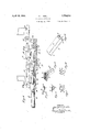
- Figure 1 is a fragmentary side elevation of portions of the wrapping mechanism, showmg the provisions for making longitudinal folds of the wrapper about an article;
- Figure 2 is a similar view showing advanced stages of the longitudinal folding of the wrapper;
- Figure 3 is a planview of the endfold wrapping means;
- Figure 4 is a sectional view taken on line 44 in Figure'l and showing the means for moving the article and its wrapper relative to the end fold wrapping means, together with the means for stationing a carton to'receive the wrapped article.
- Figures 5, 6, 7, 8 and 9 are fragmentary end views showing various stages of the wrapper folding operations; and Figure 10 is a perspective view of the completely wrapped article. Similar characters of reference are employed in the above described views, to indicate corresponding parts.
- the novel mechanism is adapted to fold a wrapper sheet about barlike articles, such e. g. as chewinggum, confectionery bars, soaprakes and similar articles of commerce.
- the underlying principles involved in this invention are the provision of stationary wrapping means with relation to which the bar to be wrapped and a sheet of flexible wrapping material may be progressively and bodily moved to effect the wrapper folds; such arrangement greatly reducing the number of moving parts and consequently greatly simplying the mechanism.
- the moving parts consist in means for moving the bar and wrapper in operative relation to the stationary fold producing devices, and it will be understood that suitable time power transmission means (not shown) may be applied to said moving parts in order to obtain desired sequential operation thereof.
- thereference character 11 indicates a folder block beneath which is arranged, in parallel relation to the under side thereof, a folder plate '12, which is spaced from said folder block 11 for adistance slightly exceeding the thickness of the bar B to be wrapped; 'Disposed in advance of said folder plate 12, and substantially level therewith, is a bar delivery platform 13, soarranged as to provide a space: 14 for tie insertion of wrapping material at the mouth of the bar receiving opening 15'intermediate the folder block 11 and folder plate 12.
- the wrapping material W is drawn from a supply roll (not shown) by the timed operation of'the feed rolls 16.
- the wrapping material (usually paper) is furnished in a width exceeding the-length of the bar B to be wrapped, and is fed dawnwardly across the mouth of said 'rece'iviiigthe shears 17 severs a portion therefromof iufiicient length -'to laterally encircle the ar B.
- the bars B are delivered from a supply thereof (not shown) by the timed reciprocation of a delivery plunger 18.
- the plunger 18 thrusts the bar sidewise along the delivery platform 13 with engagement with the wrapper sheet, which is severed from the main supply by timely operation of said shears 17 whereupon continued forward movement of the delivery plunger 18 moves the bar together with the wrapper sheet into and through the opening or passage 15, thus formin a longitudinal wrap a across the leading 51ft, of the'bar B.
- the lower end portion of the wrapper sheet is engaged by the lip 12 of the folder plate 12'and is thereby caused to fold longitudinally, as at I), under the bottom of the bar B, while the upper end portion of the wrapper sheet is engaged by the lip 11' of the folder block 11 and is thereby caused to fold longitudinally, as at a, over the top of the bar B.
- the initial feeding and positioning of the wrapper sheet is such, that the fold b is of size less than the width of the bottom of the bar B, while the fold a substantially exceeds the width of the top of said bar B so as to provide excess material to be later folded around the rear side of the bar B and under the bottom thereof.
- a vertically reciprocable plunger 19 which is initially disposed with its effective face initialy flush with the plane of said folder plate 12.
- Said plunger 19 is of a width slightly exceeding the maximum width of the bar B, and situated adjacent the far side of said plunger 19 is a stationary stop member 20.
- a secondary folder block 22 Located in the plane of said folder block 11 and spaced from the far side thereof so as to provide an intermediate passage 21 for the movement of the lunger 19, is a secondary folder block 22. cured to said secondary folder block 22 to extend transversely across the ends of the passage 21 are end folder plates 23.
- Said end folder plates 23 are each provided at their lower end portions with a .tuck finger 24 spaced downwardly from the folding lip 25 thereof, and the lower marginal edge of each tuck-fin er 24 also provides a folding lip 26 spaced s ightly above the plane of the folder plate 12.
- the bar B with the wrapper is carried out of the passage 15 and stopped against the stop member 20, thereb depositing the bar upon the plunger 19.
- the bar and wrapper move onto the plunger 19, the bar passes between the tuck-fingers 24 whereby portions of the wrapper which project beyond the ends of the bar are engaged and folded inward over the latter to form tuckfolds d and simultaneously therewith an upper end fold e and a lower end fold f to initially extend in outward horizontal lanes from the bar ends.
- the upper end folds c underlie the folding lips 25 of the end folder plates 23 and the lower end folds 7 underlie the folding lips 26 of the tucker-lingers 24.
- a longitudinally reciprocable plunger 27 isposed above the secondary folder block 22 .
- the forward stroke of the plunger 27 is timed to follow the completion of the upward stroke of the plunger 19, so that said plunger 27 may engage the bar and its wrapper, which has been raised by the plun er 19, and thereupon move the same laterally or deposit upon the upper face of the folder block 11, and against a position determining stop 28 which is fixed upon the latter.
- Said folder block 11 is provided with a pair of transverse inwardly entering vertical slots 29 and 30 aligned with the ends of the bar B.
- a channel 32 Formed in the upper face of the folder block 11 and longitudinally aligned with the longitudinal axis of a bar B deposited thereon is a channel 32.
- a cutaway portion or clearance space 38 Suitably supported above said folder block 11, and also aligned block 11 in alignment with the position'of the deposited ban-B and so as to communi cate with the rear slot 29 and underlie'the rear end of the deposited bar B, is a cutaway portion or clearance space 38, opposite which the depending terminal portions t of the rearward end folds of the wrapper are positioned when said bar B is deposited on the folder block 11 in proper position as de: termined by the stop 28.
- the bar B is so deposited the depending terminal portions t of the forward end folds of the wrapper lying in the slot 30 are opposed to a fold ing lip 30' provided by the upper edge of the outer side of said slot 30.
- means are provided for presenting an openended carton C in the path of the wrapped bar B, the same comprising a carton support or shelf 40 disposed adjacent to the outer end of the platform 39, arid preferably spaced somewhat therefrom, so that a carton closure flap retaining flange 41 may be provided to engage and remove from the path of the wrappedbar B the foldable carton closure flap p.
- the means for propelling the wrapped bar B over the platform 39 and thence into the awaiting carton comprises the following devices. Slidably arranged on the slide-rail 33, in advance of the slide-block 34 is a second slide-block 42 having a fulcrum car 43 at its lower forward end.
- a forwardly projecting impeller arm 44 having at its pivoted end an integral upwardly extending arm 45.
- This latter arm 45 is interconnected with the forward end of said slide-block 34 by a pivoted link 46.
- Projecting from the side of said link 46 rearward of the second slide-block 42 is a stud 47 which at proper times engages said rear end of said second slide-block 42 to transmit forward movement thereto.
- the link 46 moves forward therewith to thereby first swing forward the arm 45 to turn the impeller arm 44 downward on its pivotal connection so that its free end is positioned behind the rear end of a I wrapped bar B which has been previously thereto and to the impeller arm 44.
- Said inrpeller arm 44 on such forward movement engages the advanced wrapped bar B and slides the same toward and into the carton C, while atthe same time the slide-block 34 has propelled a succeeding bar from the folder block 11 to the platform 39 thereby completing the folds of the wrapper applied thereto.
- the initial pull on the link 46 first swings rearwardly the arm 45 of the impeller, thereby swinging upwardly the impeller arm 44 so that the same clears'the succeeding wrapped bar B, which has been deposited on the platform 39, whereupon the arm 45 abuts the forward end'of said second slide-block 42 to impart retractive movement thereto so that all parts of the propelling mechanism are re- Y .7
- a further advantage of the mechanism of this invention is that it produces the wrapper end folds in successive overlapping relation, whereby a tight close fitting enclosure of neat appearance is obtained.
- a stationary folder block means to provide a passage contiguous to theunderside of said folder block through which an article and wrapper therefor may be moved to produce initial longitudinal folds of the latter about the former, means to provide a second passage contiguous to a vertical face of said folder block and communicating with said first mentioned passage through which the said article and its wrapper may be moved to roduce additional longitudinal wrapper folds, end folder lates bordering said second passage, said end folder plates having tuck fingers aligned with said'first mentioned passage, said tuck fingers and end folder plates operating to produce certain end folds of the wrapper when the article and wrapper are moved past the same, means to move the article and wrapper through said first passage, means to move the article and wrapper through said second passage, means to move the article and wrapper from said second passage onto the upper surface of said folder block whereby the longitudinal wrapper folds are completed means connected with the upper side of said folder block for completing the end folds of the wrapper, a discharging means for removing
- a packaging mechanism a stationary folder block, means to provide a passage contiguous to the underside of said folder block through which an article and wrapper therefor may be moved to produce initial longitudinal folds of the latter about the former, means to provide a second passage contiguous to a vertical faceof said folder block and communicating with said first mentioned passage through which the said article and its wrapper may be moved to produce additional longitudinal wrapper folds, end folder plates bordering said second passage, said end folder plates having tuck fingers aligned with said first mentioned passage, said tuck fingers and end folder plates operating to produce certain end folds of the wrapper when the article and wrapper are moved past the same, said folder block having transverse indented slots entering the same from said second passage through which depending portions of the wrapper end folds may move as the article and wrapper are transferred from said second passage onto said folder block, upstanding folder blades mounted on said folder block respectively contiguous to said respective slots of the latter, means to move 'the article and wrapper through said first passage, means to move the article and wrapper through said second passage
- a stationary folder block having a bottom face, a rear side face and a top face respectively bounding successive portions of a path through which an article and wrapper therefor may be moved to produce successive longitudinal -folds of said wrapper around the article;
- a stationary folder block having a bottom face, a rear side face and a top face respectively bounding successive portions of a path through which an article and wrapper therefor may be moved to produce successive longitudinal folds of said wrapper around the article; means contiguous to the path of movement of said article about said folder block adapted to form end folds of the wrapper thereof; means cooperative with said folder block for inturning end folds at one end of the wrapped article; means connected with said folder block for in-turning end folds at the other end of the wrapped article; and means for moving said article and its wrapper relative to said faces of the folder block and to the end fold forming and in-turning means.
- a stationary folder block means to provide a passage contiguous to the underside of said folder through which an article and wrapper there-' for may be moved to produce initial longitudinal folds of the latter around the former, means to provide a second passage contlguous to a vertical face of said folder block and communicating with said first mentioned passage through which the article and its wrapper may be moved to produce additional longitudinal wrapper-folds, means to move a the article and wrapper through said first passage, means to move the article and wrapper through said second passage, and means to move the article and wrapper from said sec- .ond passage onto the upper surface of said folder block whereby the longitudinal wrapper folds are completed.
- a stationary folder block means to provide a passage con-. tiguous to the underside of said folder block through'which an article and wrapper therefor may be-moved to produce in1t1al longitudinal folds of the latter around the former,
- a stationary folder block means to provide a passage contiguous to the underside of said folder block through which an article and wrap r therefor may be moved to produce initial longitudinal folds of the latter around the former,
Description
April 15, 1930. G. 1. HOHL 1,7543% PACKAGING MECHANISM Filed Aug. 15, 1928 2 Sheets-Sheet 1 INVENTOR (fem g6 li 0h Z BYM 4?. MMAQ ATTORNEY April 15, 193@. HOHL 1,754,313
1 FACIKAGING MECHANISM Filed Aug. 15, 1928 2 Sheets-Sheet 2 INVENTOR ATTORN EY Patented Apr. 15, 1930 UNITED STATES" GEORGE I. HOHI OF NEWPORT, RHODE ISLAND, ASSIGNOR T0 GARTONING MACHIN- PATENT OFFICE CORPORATION, OF NEWPORT, RHODE ISLAND, A CORPORATION OF NEW mean PACKAGING MECHANISM Application filed August 15,
This invention relates to an improved mechanism for packaging articles of commerce; and the invention has reference, more particularly, to an improved means for wrapping articles and, if desired, insertmg the same in paper cartons or boxes.
The invention has for its principal object to provide a very simple mechanism for folding a paper wrapper or wrapper of other flexible material in enveloping relation to an article, which mechanism has been reduced to great simplicity, and in which the wrapper folding means are stationary, the manipulation of the wrapper being attained by bodily shifting the article with the wrapper material through-the several stationary wrapper folding devices.
The invention also has for its object to provide a novel :rrangement of machine whereby the movement of the article through the final wrapper folding means may be utilized to also insert the wrapped article in a carton or box.
Other objects of this invention, not at this time more particularly enumerated, will be clearly understood from the following detailed description of the same.
The invention is clearly illustrated in the accompanying drawings, in which Figure 1 is a fragmentary side elevation of portions of the wrapping mechanism, showmg the provisions for making longitudinal folds of the wrapper about an article; Figure 2 is a similar view showing advanced stages of the longitudinal folding of the wrapper; Figure 3 is a planview of the endfold wrapping means; and Figure 4 is a sectional view taken on line 44 in Figure'l and showing the means for moving the article and its wrapper relative to the end fold wrapping means, together with the means for stationing a carton to'receive the wrapped article.
Figures 5, 6, 7, 8 and 9 are fragmentary end views showing various stages of the wrapper folding operations; and Figure 10 is a perspective view of the completely wrapped article. Similar characters of reference are employed in the above described views, to indicate corresponding parts.
successive formation of the 1928. Serial No. 299,679.
The novel mechanism, according ,to this invention, is adapted to fold a wrapper sheet about barlike articles, such e. g. as chewinggum, confectionery bars, soaprakes and similar articles of commerce. The underlying principles involved in this invention are the provision of stationary wrapping means with relation to which the bar to be wrapped and a sheet of flexible wrapping material may be progressively and bodily moved to effect the wrapper folds; such arrangement greatly reducing the number of moving parts and consequently greatly simplying the mechanism. The moving parts consist in means for moving the bar and wrapper in operative relation to the stationary fold producing devices, and it will be understood that suitable time power transmission means (not shown) may be applied to said moving parts in order to obtain desired sequential operation thereof.
Referring now to said drawings, thereference character 11 indicates a folder block beneath which is arranged, in parallel relation to the under side thereof, a folder plate '12, which is spaced from said folder block 11 for adistance slightly exceeding the thickness of the bar B to be wrapped; 'Disposed in advance of said folder plate 12, and substantially level therewith, is a bar delivery platform 13, soarranged as to provide a space: 14 for tie insertion of wrapping material at the mouth of the bar receiving opening 15'intermediate the folder block 11 and folder plate 12. Located above the folder block 11, and vertically aligned substantially in the plane of the mouth of the bar receiving opening 15. intermediate the folder block 11 and folder plate 12, are apair of wrapping material feed rolls l6, beneath which are located the wrapper cutter shears 17. The wrapping material W is drawn from a supply roll (not shown) by the timed operation of'the feed rolls 16. The wrapping material (usually paper) is furnished in a width exceeding the-length of the bar B to be wrapped, and is fed dawnwardly across the mouth of said 'rece'iviiigthe shears 17 severs a portion therefromof iufiicient length -'to laterally encircle the ar B.
The bars B are delivered from a supply thereof (not shown) by the timed reciprocation of a delivery plunger 18. The plunger 18 thrusts the bar sidewise along the delivery platform 13 with engagement with the wrapper sheet, which is severed from the main supply by timely operation of said shears 17 whereupon continued forward movement of the delivery plunger 18 moves the bar together with the wrapper sheet into and through the opening or passage 15, thus formin a longitudinal wrap a across the leading 51ft, of the'bar B. As the bar and wrapper sheet enter said opening or passage, the lower end portion of the wrapper sheet is engaged by the lip 12 of the folder plate 12'and is thereby caused to fold longitudinally, as at I), under the bottom of the bar B, while the upper end portion of the wrapper sheet is engaged by the lip 11' of the folder block 11 and is thereby caused to fold longitudinally, as at a, over the top of the bar B. The initial feeding and positioning of the wrapper sheet is such, that the fold b is of size less than the width of the bottom of the bar B, while the fold a substantially exceeds the width of the top of said bar B so as to provide excess material to be later folded around the rear side of the bar B and under the bottom thereof.
Located at the far side of said folder plate 12 is a vertically reciprocable plunger 19, which is initially disposed with its effective face initialy flush with the plane of said folder plate 12. Said plunger 19 is of a width slightly exceeding the maximum width of the bar B, and situated adjacent the far side of said plunger 19 is a stationary stop member 20. Located in the plane of said folder block 11 and spaced from the far side thereof so as to provide an intermediate passage 21 for the movement of the lunger 19, is a secondary folder block 22. cured to said secondary folder block 22 to extend transversely across the ends of the passage 21 are end folder plates 23. Said end folder plates 23 are each provided at their lower end portions with a .tuck finger 24 spaced downwardly from the folding lip 25 thereof, and the lower marginal edge of each tuck-fin er 24 also provides a folding lip 26 spaced s ightly above the plane of the folder plate 12.
As the delivery plunger 18 completes its inward stroke the bar B with the wrapper is carried out of the passage 15 and stopped against the stop member 20, thereb depositing the bar upon the plunger 19. XS the bar and wrapper move onto the plunger 19, the bar passes between the tuck-fingers 24 whereby portions of the wrapper which project beyond the ends of the bar are engaged and folded inward over the latter to form tuckfolds d and simultaneously therewith an upper end fold e and a lower end fold f to initially extend in outward horizontal lanes from the bar ends. As the bar is fina ly deposited on the plunger 19, the upper end folds c underlie the folding lips 25 of the end folder plates 23 and the lower end folds 7 underlie the folding lips 26 of the tucker-lingers 24.
When the bar is positioned'as above stated upon the plunger 19, timed actuation of the plunger 19 causes the same to rise with the bar and its wrapper through the passage 21, with the following effects. The fold a is engaged by the lower rear lip 11" of the folder block 11 whereby the same is caused to be turned downwardly and thus folded over the adjacent side of the bar to produce the side covering fold g, while also forming end folds to extend in vertical plane beyond the ends of the bar and at the same time the lower end fold f and the upper end fold e are turned down as they are carried upwardly past the respective folding lips 26 and 25 as the bar is lifted upwardly between the end folder plates 23. The upward stroke of the plunger 19 raises the bar to the level of the top or up er surface of the folder block 11.
isposed above the secondary folder block 22 is a longitudinally reciprocable plunger 27. The forward stroke of the plunger 27 is timed to follow the completion of the upward stroke of the plunger 19, so that said plunger 27 may engage the bar and its wrapper, which has been raised by the plun er 19, and thereupon move the same laterally or deposit upon the upper face of the folder block 11, and against a position determining stop 28 which is fixed upon the latter. Said folder block 11 is provided with a pair of transverse inwardly entering vertical slots 29 and 30 aligned with the ends of the bar B. As the plunger 27, onits operative forward stroke, moves the bar B and its wrapper toward the folder block 11, the free depending end of the side covering fold g is engaged by the upper rear folding lip 11" of the folder block 11 whereby the same is caused to be turned under the bottom of the bar to form the final longitudinal lap fold 9, while at the same time the folds h are engaged by folder ears 31 which are respectively mounted on the folder block 11 adjacent to the outer sides of the res ective slots 29 and 30 near the upper rear fo ding lip 11". Said folder ears 31 serve to turn back said folds it over the ends of the bar and the previously formed folds e and f. As the bar B thus far wrapped moves upon the folder block 11, the depending terminal portions t of the end folds respectively ride into the said slots 29 and 30.
Formed in the upper face of the folder block 11 and longitudinally aligned with the longitudinal axis of a bar B deposited thereon is a channel 32. Suitably supported above said folder block 11, and also aligned block 11 in alignment with the position'of the deposited ban-B and so as to communi cate with the rear slot 29 and underlie'the rear end of the deposited bar B, is a cutaway portion or clearance space 38, opposite which the depending terminal portions t of the rearward end folds of the wrapper are positioned when said bar B is deposited on the folder block 11 in proper position as de: termined by the stop 28. \Vhen the bar B is so deposited the depending terminal portions t of the forward end folds of the wrapper lying in the slot 30 are opposed to a fold ing lip 30' provided by the upper edge of the outer side of said slot 30. 7 A
After the bar B withthe thus far folded wrapper is deposited on the folder block 11, in the manner above stated, timed actuation of said slide-block 34 is initiated whereby the same moves forward toward and into engagement with the rear end of said bar B. Under this operation the forwardly projecting folding finger 37 engages the said depending terminal portions t of the rearward end folds of the wrapper, and swings such parts upwardly through the clearance space 38 to underlie the bottom of the bar, and on completion of this operation the push-piece 36 is brought into engagement with the rear end of the bar B. Continued movement of the slide-block 34 now moves the bar B longi terminal portions t of the end folds of the wrapper will be engaged between the upper surface of the folder block 11 and the bottom of the bar B and thus held in final folded position, and at the end of the forward stroke of the slide block 34 the completely wrapped bar B will be moved off of the folder block 11 into a receiving platform 39 whichis disposed fiush with the same.
As shown in Figure 4 of the drawings, means are provided for presenting an openended carton C in the path of the wrapped bar B, the same comprising a carton support or shelf 40 disposed adjacent to the outer end of the platform 39, arid preferably spaced somewhat therefrom, so that a carton closure flap retaining flange 41 may be provided to engage and remove from the path of the wrappedbar B the foldable carton closure flap p. i The means for propelling the wrapped bar B over the platform 39 and thence into the awaiting carton, comprises the following devices. Slidably arranged on the slide-rail 33, in advance of the slide-block 34 is a second slide-block 42 having a fulcrum car 43 at its lower forward end. .Pivoted to said fulcrum car 43 is a forwardly projecting impeller arm 44 having at its pivoted end an integral upwardly extending arm 45. This latter arm 45is interconnected with the forward end of said slide-block 34 by a pivoted link 46. Projecting from the side of said link 46 rearward of the second slide-block 42 is a stud 47 which at proper times engages said rear end of said second slide-block 42 to transmit forward movement thereto. As the'slide-block 34 is moved forward on its. operative stroke, the link 46 moves forward therewith to thereby first swing forward the arm 45 to turn the impeller arm 44 downward on its pivotal connection so that its free end is positioned behind the rear end of a I wrapped bar B which has been previously thereto and to the impeller arm 44. Said inrpeller arm 44 on such forward movement engages the advanced wrapped bar B and slides the same toward and into the carton C, while atthe same time the slide-block 34 has propelled a succeeding bar from the folder block 11 to the platform 39 thereby completing the folds of the wrapper applied thereto. On the retractive stroke of the slide-block 34, the initial pull on the link 46 first swings rearwardly the arm 45 of the impeller, thereby swinging upwardly the impeller arm 44 so that the same clears'the succeeding wrapped bar B, which has been deposited on the platform 39, whereupon the arm 45 abuts the forward end'of said second slide-block 42 to impart retractive movement thereto so that all parts of the propelling mechanism are re- Y .7
turned to normal initial positions.
From the above description of the construction and operation of the mechanism it will be understood that the articles passed therethrough will be enveloped in their wrappers in a rapid and efficient manner; and since the means for producing folds of the wrappers are stationary, the wrapping operations are eflectedmerely by moving the articles and their wrappersstep by step relative to said folding means. Such arrangement results in a very simple and easily timed and actuated mechanism which may be continuously operated, and which is little likely to become accidentally disarranged in use.
A further advantage of the mechanism of this invention is that it produces the wrapper end folds in successive overlapping relation, whereby a tight close fitting enclosure of neat appearance is obtained.
As many changes could be made in the above described construction and many apparently widely different embodiments of this invention could be made without departing from the scope thereof, it is intended that all matter contained in the above description as shown in the accompanying drawings shall be interpreted as illustrative and not in a limiting sense.
I claim 1. In a packaging mechanism, a stationary folder block, means to provide a passage contiguous to theunderside of said folder block through which an article and wrapper therefor may be moved to produce initial longitudinal folds of the latter about the former, means to provide a second passage contiguous to a vertical face of said folder block and communicating with said first mentioned passage through which the said article and its wrapper may be moved to roduce additional longitudinal wrapper folds, end folder lates bordering said second passage, said end folder plates having tuck fingers aligned with said'first mentioned passage, said tuck fingers and end folder plates operating to produce certain end folds of the wrapper when the article and wrapper are moved past the same, means to move the article and wrapper through said first passage, means to move the article and wrapper through said second passage, means to move the article and wrapper from said second passage onto the upper surface of said folder block whereby the longitudinal wrapper folds are completed means connected with the upper side of said folder block for completing the end folds of the wrapper, a discharging means for removing a wrapped article from said folder block; said discharging means having a finger for inturning end folds at one end of the wrapped article, and means connected with said folder block for inturning the end folds'at the opposite end of the wrapped article as the same is discharged from said folder block.
2. A packaging mechanism, a stationary folder block, means to provide a passage contiguous to the underside of said folder block through which an article and wrapper therefor may be moved to produce initial longitudinal folds of the latter about the former, means to provide a second passage contiguous to a vertical faceof said folder block and communicating with said first mentioned passage through which the said article and its wrapper may be moved to produce additional longitudinal wrapper folds, end folder plates bordering said second passage, said end folder plates having tuck fingers aligned with said first mentioned passage, said tuck fingers and end folder plates operating to produce certain end folds of the wrapper when the article and wrapper are moved past the same, said folder block having transverse indented slots entering the same from said second passage through which depending portions of the wrapper end folds may move as the article and wrapper are transferred from said second passage onto said folder block, upstanding folder blades mounted on said folder block respectively contiguous to said respective slots of the latter, means to move 'the article and wrapper through said first passage, means to move the article and wrapper through said second passage, means to move the article and wrapper from said second passage onto the upper surface of said folder bloclrwhereby the longitudinal wrapper folds are completed and additional end folds are produced by said folder blades, a stop on said folder block for positioning the articleand wrapper thereon, said folder block having a cutaway portion communicating with one of said slots thereof, a discharging means for removing a wrapped article from said folder block, and said discharging means having a finger for inturning end folds at one end of the wrapped article through said cutawa portion and under said article, the end folds at the opposite end of said wrapped article being inturned beneath the same by engagement with the margin of the other of said slots when said wrapped article is discharged from said folder block.
3. In a packaging mechanism, a stationary folder block having a bottom face, a rear side face and a top face respectively bounding successive portions of a path through which an article and wrapper therefor may be moved to produce successive longitudinal -folds of said wrapper around the article;
means contiguous to the path of movement of said article about said folder block adaptedto form end folds of the wrapper; and means for moving said article and its wrapper relative to said faces of the folder block and to the end fold forming means.
4. In a packaging mechanism, a stationary folder block having a bottom face, a rear side face and a top face respectively bounding successive portions of a path through which an article and wrapper therefor may be moved to produce successive longitudinal folds of said wrapper around the article; means contiguous to the path of movement of said article about said folder block adapted to form end folds of the wrapper thereof; means cooperative with said folder block for inturning end folds at one end of the wrapped article; means connected with said folder block for in-turning end folds at the other end of the wrapped article; and means for moving said article and its wrapper relative to said faces of the folder block and to the end fold forming and in-turning means.
5. In a packaging mechanism, a stationary folder block, means to provide a passage contiguous to the underside of said folder through which an article and wrapper there-' for may be moved to produce initial longitudinal folds of the latter around the former, means to provide a second passage contlguous to a vertical face of said folder block and communicating with said first mentioned passage through which the article and its wrapper may be moved to produce additional longitudinal wrapper-folds, means to move a the article and wrapper through said first passage, means to move the article and wrapper through said second passage, and means to move the article and wrapper from said sec- .ond passage onto the upper surface of said folder block whereby the longitudinal wrapper folds are completed.
6.; In a packaging mechanism, a stationary folder block, means to providea passage con-. tiguous to the underside of said folder block through'which an article and wrapper therefor may be-moved to produce in1t1al longitudinal folds of the latter around the former,
means to provide a second passage contiguous to' a vertical face of said folder block and communicating with said first mentioned passage through which the. article and its wrapper may be moved to produce additional longi tudinal wrapper folds, means to move the article and wrapper through said first pas sage,means to move the article and wrapper through said second passage, means to move I thearticle and wrapper from said second passage onto the upper surface of said folder block whereby the longitudinal wrapper folds are'completed, means bordering said second passage to form certain end folds *of :the wrapper, and means at the upper side of said wrapper.
means cooperative with said folder block for in-turning the extremities of the end folds of the wrapper as the wrapped article is discharged from the upper side of said folder 7 block.
In testimony, that I claim the invention set forth above I have hereunto set my hand this I 27th day of July, 1928.
' GEORGE I. HOHL.
7.. In a packaging mechanism, a stationary folder block, means to provide a passage contiguous to the underside of said folder block through which an article and wrap r therefor may be moved to produce initial longitudinal folds of the latter around the former,
means to provide a second passage contiguous I to a vertical face of said folder block and communicating with said first mentioned passagethrough which the article and its wrapper may be moved to produce additional longitudinal wrapper folds, means to move the article and wrapper through said first passage, means to move the article and wrapper through said second passage, means to move the article and wrapper fromsaid sec ond passage onto the upper surface of said folder block whereby the longitudinal wrapa per folds are completed, means bordering said second passage to form certain end folds of the wrapper, means connected with the upper side of said folder block for makin additional end foldsof the wrapper, an
Priority Applications (1)
| Application Number | Priority Date | Filing Date | Title |
|---|---|---|---|
| US299679A US1754318A (en) | 1928-08-15 | 1928-08-15 | Packaging mechanism |
Applications Claiming Priority (1)
| Application Number | Priority Date | Filing Date | Title |
|---|---|---|---|
| US299679A US1754318A (en) | 1928-08-15 | 1928-08-15 | Packaging mechanism |
Publications (1)
| Publication Number | Publication Date |
|---|---|
| US1754318A true US1754318A (en) | 1930-04-15 |
Family
ID=23155788
Family Applications (1)
| Application Number | Title | Priority Date | Filing Date |
|---|---|---|---|
| US299679A Expired - Lifetime US1754318A (en) | 1928-08-15 | 1928-08-15 | Packaging mechanism |
Country Status (1)
| Country | Link |
|---|---|
| US (1) | US1754318A (en) |
-
1928
- 1928-08-15 US US299679A patent/US1754318A/en not_active Expired - Lifetime
Similar Documents
| Publication | Publication Date | Title |
|---|---|---|
| US2289820A (en) | Machine for opening shipping cases from the flat | |
| CA1111336A (en) | Arrangement for filling a receptacle having self- contained closure means | |
| US1816085A (en) | Wrapping machine and process | |
| US2208776A (en) | Wrapping machine | |
| US2071247A (en) | Carton closing machine | |
| US3041806A (en) | Machine for forming lined packages | |
| US1754318A (en) | Packaging mechanism | |
| US2095938A (en) | Cigar packing machine | |
| US2969631A (en) | Cigarette packaging machine | |
| US2464099A (en) | Packaging machine | |
| US2195916A (en) | Egg carton assembling machine | |
| US2177773A (en) | Method and apparatus for wrapping prints of butter or the like | |
| US2652669A (en) | Packaging table-ready meats | |
| US3530643A (en) | Apparatus for packaging books | |
| US1993389A (en) | Machine for wrapping and boxing articles | |
| US2987974A (en) | Machine for opening and handling cartons of packaging machinery | |
| US2522234A (en) | Wrapping machine for razor blades or the like | |
| US1313974A (en) | anderson | |
| US2385675A (en) | Tucking and folding mechanism for wrapping machines | |
| US2050818A (en) | Wrapping machine | |
| US2216447A (en) | Cigarette package forming machine | |
| US2874527A (en) | Wrapping machine | |
| US1573024A (en) | Stacking machine | |
| US3029572A (en) | Cigarette packaging machine | |
| US2668406A (en) | Wrapping or packing machine |