US1754317A - Bender for thin-wall conduits - Google Patents
Bender for thin-wall conduits Download PDFInfo
- Publication number
- US1754317A US1754317A US320926A US32092628A US1754317A US 1754317 A US1754317 A US 1754317A US 320926 A US320926 A US 320926A US 32092628 A US32092628 A US 32092628A US 1754317 A US1754317 A US 1754317A
- Authority
- US
- United States
- Prior art keywords
- conduit
- groove
- bending
- bent
- flanges
- Prior art date
- Legal status (The legal status is an assumption and is not a legal conclusion. Google has not performed a legal analysis and makes no representation as to the accuracy of the status listed.)
- Expired - Lifetime
Links
Images
Classifications
-
- B—PERFORMING OPERATIONS; TRANSPORTING
- B21—MECHANICAL METAL-WORKING WITHOUT ESSENTIALLY REMOVING MATERIAL; PUNCHING METAL
- B21D—WORKING OR PROCESSING OF SHEET METAL OR METAL TUBES, RODS OR PROFILES WITHOUT ESSENTIALLY REMOVING MATERIAL; PUNCHING METAL
- B21D7/00—Bending rods, profiles, or tubes
- B21D7/06—Bending rods, profiles, or tubes in press brakes or between rams and anvils or abutments; Pliers with forming dies
- B21D7/063—Pliers with forming dies
Description
April 15, 1930. R. H. HENDERSON 1,754,317
BENDER FOR THIN WALL CONDUITS Filed Nov. 21. 1928 2 Sheets-Sheet l I N V EN TOR. flkriials' rlmwog April 1930. R. H. HENDERSON 1,754,317
BENDER FOR THIN 'WALL GONDUITS Filed Nov. 21. 1928 2 Sheets-Sheet 2 WWW/MM ATTORNEY Patented Apr. 15, 1930 PATENT OFFICE ROBERT HAESEY HENDERSON, or EAST ORANGE, INAEW JEEsEY BENIDER FOR THIN-WALL CONDITI'IS Application filed November 21, 1928. Serial no. 320,926.
This invention relates, generally, to improvements in hand conduit benders; and the invention has reference, more particular- 1y, to an improved hand bender or hickey of the general kind shown and described in my heretofore granted Letters Patent of the United States, No. 1,627,034, dated May 3rd, 1927. y i
In my aforesaid prior patent, I have pointed out certain essential characteristics which the main bending groove of a hickey must possess in order to bend thin wall conduit or tubing without distortion or collapse, and which include the provision of compensating relief or expansion surfaces in connection with the seat of said niain bending groove.
As aresult of continued study and experiment in the art of bending thin wall conduit by means of hand benders or hickeys, I have discovered certain critical requirements for the hickey structure, necessary for efficient control of a thin wall conduit at every stage or zone influenced by bending stresses, not only so as to assure bends wlthout kinks or crushing, but also to produce ultimate or finished bends which are substantially smooth in sweep and contour (i. e. free from lateral humps or ridges), and which are also free from longitudinal twists.
The present invention has for its principal object to provide an improved construction of hand bender or hickey having a combination of novel forms of conduit supports at each stage or zone influenced by bending stresses, whereby the molding or shaping of thin Wall conduit, both as to the ultimate axial curvature thereof, and as to retention of the desired substantially round cross sectional shape thereof, is progressively attained by the step by step operation of the hickey in the usual manner. The novel construction of hiclrey embodying the principles of this invention provides both adequaterexternal support for the conduit at each part or zone thereof subject to bending stresses when'under applied bending pressures, as well as certain critical clearance especially adapted to the conditions obtaining at each particular part or zone, all as hereinafter more particularly set forth in the following specification.
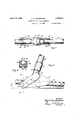
The presentinvention is illustrated in the accompanying drawings, in which Figure 1 is a plan or top view of a hand bender or hickey adapted for bending light gauge or thin wall metal conduit, and embodying the novel features of construction according to this invention, said View showverse vertical section taken on line 66 in said Figure 5.
Similar characters of references are employed in all of the said views to indicate corresponding parts.
The novel bender or hickey, as shown in the drawings, andas adapted to function in connection with light gauge or thin wall conduit,'co1nprises a main body or head 10 having a threaded shank 11 to receive a suitable coupling 12 for attaching the same to one end of the hand or manipulating lever 13. V V
The main body or head 10 is formed to provide a curved element 14, the periphery of which is approximately semi-circular, and in- V tegral with the curved element, at each side thereof, are flanges 15 and 16 spaced apart at a critical distance to be hereinafter more particularly referred to. The curved'elernent 14 and the side flanges 15 and 16 together form a main bending groove, the seat of which is provided with compensating expansion spaces 17, lying respectively between the central points of the groove and the side gripping points provided by the side flanges 15 and 16, the same being formed by slightly deepening the groove at such points, substantially as and for the purposes described in my heretofore mentioned prior Patent No. 1,6279%. The longitudinal curvature of the curved GlQRIlQlll] 1 1 is of considerably shorter radius than the radius of the curvature of an elbow or other bend to be formed in the conduit 18.
Integrally formed in connection with the flanges 15 and 16 are rearwardly projecting wings or extensions 15 and 16, the same being prolongations of said flanges 15 and 16 extending rearwardly from the bending point of said curved element 14 for a distance approximating from two and one-half to three times the diameter of the conduit 18 to be bent. The inner surfaces of the flange extensions 15 and 16 are slightly divergent from the main bending groove toward the rear ends of said flange extensions, thus providing divergent surfaces 15 and 16" whereby the receiving space through which the conduit enters and through which it is shifted toward the main bending groove, during step by stepbending operations, is of slightly increasing width rearwardly. The gradual increase of the width of this receiving space is critically dimensioned, as will be hereinafter more fully stated, and for purposes to be also subsequently explained.
Integrally formed with and so as to extend from the forward ends of the flanges 15 and 16 are arms 19 and 20, adapted to provide a bifurcated or fork like forward extension of the hiekey body. Mounted between the free end portions of said arms 19 and 20 is a supporting abutment or member 21, which is thus positioned within the embrace of said arms, and which is pivotally eonnected with said arms by a transverse fulcrum pin 22, so that said supporting member may turn on an axis at right angles to the longitudinal axis of the conduit being bent, and thereby enabling the supporting member to both withstand and adjust itself to the thrustof the conduit incident to the bending operation.' Said supporting member is provided with a groove 23 having a semi-circu 'lar cross-sectional shape conforming to the normal cross-sectional shape of the conduit being bent. The sides of said groove 23 are extended upwardly in substantially parallel relation for a distance'exceeding the radiusof the cross sectional circumference of the conduit, thus providing molding surfaces 24 "L0 function in the manner hereinafter. set forth. The supporting member 21 provides an abutment or thrust against which bending pressure is exerted, and I find it desirable that the point of bearing of said supporting member upon the conduit should be spaced from the main bending groove, provided by the curved element 14 and the flanges 15 and 16, for a distance approximating two and one-half to three times the diameter of .JhG'COIIdUit to be bent.
The novel bender orhiekey constructed generally in the manner above described, and adapted for bending thin wall conduit, has three different and essential mechanical features, each of which has its own particular function in the total operation of bending such thin wall conduit or other tubing possessing similar characteristics.
These three features are First. The grooved supporting member, which is pivoted so as to automatically adjust itself to the curvature produced by the bending operation, and which is provided with the conduit receiving groove critically dimensioned to substantially correspond to the normal dimensions and circumference of the conduit whereby, as the conduit is caused to press down into the seat provided by the groove a counteracting shaping or molding efiect is obtained, tending to return bent sec tions of the conduit to a substantially round cross-sectional shape.
Second. The shape, dimensions and relative location of the main bending groove where the greatest bending stress or pressure is applied to the conduit for the purpose of imparting thereto a desired curvature; the shape of the seat of which provides the compensating relief spaces 17 and, in addition thereto, a spaced relation of the flanges 15 and 16 adapted to permit of a controlled lateral expansion of the conduit walls while undergoing bending stresses.
Third. The rearward extensions 1516' of the flanges 15 and 16, which by reason of their opposed diverging inner surfaces 15 and 16", allow for lateral expansion of the conduit rearwardly of the main bending point within collapsing limits but in excess of elastic limits of said conduit.
Before setting forth in detail certain critical dimensions which it is desirable that the above enumerated features should possess, it may be stated that hand benders or hickeys are madein several assorted sizes corresponding to standardized diameter sizes of conduit employed in electrical work; and consequently benders and hickeys are furnished to fit each size of such conduit, therefore, the critical dimensions hereinafter referred to always have a given relation to the diameter and wall gauge thickness of the particular conduit which a given bender or hickey is sized to serve.
Since thin wall conduit does not possess sufficient wall thickness to permit of cutting threads therein, compression couplings or bushings are used at all points v-Jhere conduit sections are joined in end to end relation, and consequently it is highly desirable that the ends of conduit sections, and especially bent sections such as elbows, should retain their original or normal true circular cross sectional contour. For this reason the supporting member must be so constructed as to not distort the conduit at its end portion, and this must be accomplished in spite of the fact that the strain of the initial bend is very severe at such point, since such initial bend constitutes what is known as breaking down the conduit. Once'the bending operutionisinitiuted endthe breaking down effect begun,
:to roll sideways the least bit "between the successive or step by step bending opera- -t1ons,e resultant longitudinal twist likely sto be formed in the finlshed work. Such longitudinal twist tends to displace the relotive axial alignment of the end PJJ'JlOIRS oi the conduit sections, and renders it dithcult to couple up such sections when installiup; the'conduit. In the hickey of this invention. I overcome tendency to distortion of the end portions 01? the conduit, and of longitudin ully twisting theconduit bodyst the place of bend mulkingthe groove in the supper ing member long enough to give a substantial bearing on the conduit 'filt all times, and also to .Q'ivesuliicient guidenceto the conduit so to eil'ectuully prevent rolling with con sequent twisting. I find in this connection that u length of groove approximating the diemetc. of the conduit being bent will. give the substantial bearing support desired; at the some time the depth of the groove is made to enccedthe cross section jl radius oat-the conduit so-thet the side walls of said groove not only provide ample support against lateral expansion or distortion, but actually tend to bring; laterally expanded Wells of the corn dui't beck towerrl true circular contour. In addition to such sizing of the length and depth otthe groove olseid supporting meniber, I also find it desirable to pivotelly mount the latter so that it is free to automatically itself to proper bearing upon the upcurved conduit portion the bending operations are initiated and continued. in hic'lroys designed to lit end. bend thin Well conduit of smaller diemetric sizes it may be suilicient to *lormthe supportingmember as e. onury or integral part of the hickey body, provided core is given in determining the correctpitch or angle of the groove thereof, and provided that the critical dimensions elreudy referred to are included. Inasmuch as the cross-sectional shape of successive portions of he conduit bend, made subsequent to the initial bending operation, ere made under conditions ellowing for lateral expansion oi the conduit wells with consequent slight lateral deformation from a. true or perfeet circular cross sectional shape, I find it highly desirable to critically dii'nension the width of the groove ofseid supporting momher so that such succeeding portionsof the conduit bend ere submitted to s compensatingsheping or molding pressure us the conduit portions are shifted to and ereceused to enter endbe pressed dorm into the seat of the groove; and to this end, the Width of the groove .must be at leustthe diameter-of the conduit being bent plus the mill toleronce which will vary between live and ten thousendths, according to the method by which. the conduit tubing is made, and according to the grade end llrind of mete-l of which it is composed. In "this connection it may be desirable, especially in hickeys designed to bend the larger dieinetricsizes of thin wall conduit, to have the side walls of the groove slightly divergent from its forwardtowerd its rearward. end, so that the width of said groove at the rearward end, or toward the point into which the conduit enters the some, is slightly in ex:- cess of such lateral widening of the conduit as may occur without exceeding the elastic limit of the conduit. 1 have found in this connection that the maximum width at such point may approximate the diemeter'of the conduit plus one and one-half times the limit of the lateral distortion which would be setup by its elastic limit. It will be-o-bvious that the groove cit-the supporting member, when constructed and dimensioned in the manner :ztbove stated, will permit of a shaping or molding effect to be exerted is the conduit is forced into seated relation thereto under successively applied bending pressures.
l Iith regard to that portion of the hickey wherein the main bendinggroove is provided, and at which point maximum bending pressures ere transmitted to theconduit, I have found that such :main bending groove should be spaced rearwerdly from the supporting member for a distance approximating two and one-halt to three timesthediemeter ofthe conduit being bent. The said main bending groove, which is formed as heretofore stated by the curved element 14 and the bounding side flanges do and 16, should have a depth approximating the diameter of the conduit being bent, and can if desired exceed such depth; the seat or bottomof this groove, however, must possess the compensating expansion spaces 17 lying respectively between the central points of the groove end the side gripping points provided by the side flanges 1'5 and 16, the some being formed by slightly deepening the groove at such points, as heretofore mentioned. In addition to this conformation, 1 find that the width oi": the main bending groove, i. e. the'space between the inner surfaces of the flanges T15 and 16, particularly at points positioned from the bottom or seat 'of the grooveete distance approxinurting the crosssectional radius of the conduit being bent, should be equivalent to the diameter of the conduit plus a clearance of one and one-half to one and three-quarters of the elastic limit of the conduit (and by elastic limit, I mean the distance to which the walls of the conduit may be expanded by applied pressure in a given direction with possibility of returning to original contour under the reaction of inherent elasticity) It will thus be noticed that I find it advisable to provide a width of main bending groove which is calculated to permit of slight lateral expansion of the walls of the conduit beyond their elastic limit, since by such lateral expansion strains tending to kink, laterally ridge or collapse the conduit are sufficiently relieved before such undesired effects occur,
while nevertheless furnishing side support to the conduit calculated to restrain undue ex pansion and to prevent collapse or distortion thereof. By such functioning of the main bending groove it will be obvious that a slight lateral expansion of the conduit occurs which will remain in the conduit as the same is shifted step by step during the bending operations, but which when such point reaches the supporting member is subjected to a slight external lateral pressure tending to bring the cross sectional shape of the conduit back toward a true circular contour.
I have further found it of considerable importance to rearwardly project the flanges forming the side walls of the main bending groo e for a distance approximating from two and one-half to three times the diameter of the conduit being bent. I have further found that when bending pressures are applied to the conduit, that portions. of the latter which extends rearwardly from the main bending groove is subject to stresses tending to laterally expand or flatten the conduit, and that such tendency is desirable to a certain degree, since it tends to distribute the bend ing stresses and allows for a better adjustment of the metal to the shape of bend sought. In order to assure that no excess latitude is allowed for such lateral expansion of the rearwardly extending portion of the conduit I have found it very desirable that the inner faces of the flange extensions 15 and 16 should be longitudinally divergent rearwardly from the main bending groove. This divergence should be of such pitch or degree that, at the free extremities of the flange extensions, the width of the conduit receiving spaceshould reach its maximum and should not execeed the diameter of the conduit plus two or three times the elastic limit thereof.
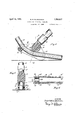
I will now describe the operation of the hickey with special relation to the cooperation of the various mechanical features above explained. In order to facilitate a clear understanding of the operations and effects involved, the sphere ofinfluence exercised by each of the functional parts of the hickey relative to the conduit to be bent may be designated as zones A, B, C and D. These zones are indicated in Figure 5 of the drawing. Zone A refers to that portion of the conduit which is immediately acted upon by the supporting member 21; zone B indicates that portion of the conduit which is immediately acted upon by the main bending groove constituted by the curved element 14: and its side wall flanges 15 and 16; zone C refers to that portion of the conduit immediately acted upon by the longitudinally and rearwardly divergent flange extensions 15 and 16; and zone D refers to that portion of the conduit extending rearwardly from the hickey and in the immediate vicinity thereof.
To begin a bending operation the hickey is slipped over the end of the thin wall conduit 18, and positioned thereon so that a forward portion of the conduit projects beyond the supporting member 21, so that substantially no bending stresses are applied thereto during the bending operation, to the end that its true circular cross sectional shape is undisturbed, and consequently such portion is ready to receive proper fitting engagement of a compression coupling. The conduit lies on the floor and extends rearwardly from the thus applied hickey. The curved element 14 of the main bending groove impinges upon the top side of the conduit when thus positioned. The operator now pulls rearwardly on the lever handle 13 of the hickey, thus tending to bend upwardly the forward end portion of the conduit under the oppositely applied pressures exerted by the supporting member 21 and curved element 14. of the main bending groove. As the bending pressure is thus applied, the conduit is placed under stresses which are strictly restrained by the close fitting engagement of the supporting member 21, so that zone A of the conduit is strongly supported against lateral expansion; at zone B the applied pressure and resultant stresses causes the conduit to expand laterally to the limits allowed by the seat shape of the bending groove and by the critical width dimensions established be tween the flanges 15 and 16 of the groove, thus permitting the conduit to bend while at the same time distributing the stresses until the resultant lateral expansion is stopped by impingement of the sides of said conduit in supported contact with the flanges 15 and 16. The bending stresses tending to produce lateral expansion of the conduit are distributed rearwardly from the point of impingement of the curved element of said main bending groove, and owing to the diverging relation of the internal sides of the flange extensions 15 and 16', a progressively increasing lateral expansion through the zone C is permitted within the limits of the support afforded by said flange extensions 15 and 16, while beyond said flange extensions and within zone D further lateral expansion is unrestrained, but will not be excessive, since the skilled operator will not attempt to make long step bends likely to break down or collapse the conduit at zone I), but rather produces the bends by short steps effected by frequent rearward shifting of the hickey upon the conduit.
From the above description, it will be apparent that the conduit bending is progressively accon'iplished, step by step, by shifting the conduit forwardly between the main bending groove and the supporting member 21. After the initial bending step it will be apparent that the conduit at zone D possesses the maximum lateral expansion. As the conduit is shifted forward relative to the hickey and a succeeding bending step is effected, zone D is brought under the influence of the flange extensions 15 and 16; zone C is brought under the influence of the main bending groove and its more closely spaced flanges 15 and 16, and consequently a shaping or molding effect is obtained tending to return the contour of the conduit toward its true circular form while yet still retaining, at such point, sufficient lateral expansion to distribute the bending stresses for prevention of buckles or kinks; as zone B shifts toward and is brought into engagement with the supporting member 21, a further shaping or molding effect upon this portion is obtained to further return zone B of the bent conduit toward true circular cross-sectional shape. It will thus be seen that with each bending operation the respective effects occuring at the different zones of the conduit are siniultaneously wrought, yet by the progressive and successive bending operations a given portion of the conduit is successively carried through the bending operations, and is progressively subjected to the peculiar effects occurring at each stage thereof, and that a progressive molding, shaping or coining of the conduit while being bent tends to both support the same against kinking or collapse, while at the same time tending to ultimately produce bent conduit having smooth longitudinal curve and having substantially circular cross sectional shape.
Having thus described my present invention, it claim 1. A hand bender for thin wall conduit, comprising a curved element having a handle lever extending therefrom, said element having integral side flanges forming therewith a peripheral main bending groove, said flanges being laterally spaced apart for a distance slightly exceeding the diametric elas tic limit of the conduit to be bent, said bending groove having clearance spaces intermediate the bottom of its seat where the conduit to be bent impinges and the sides thereof as formed by said spaced flanges; and a supporting member forwardly ofi set beyond said main bending groove at a distance equivalent to two to three times the diameter of the conduit to be bent; said supporting member having a bearing groove of substantial length to receive and engage the conduit to be bent,
said bearing groove having a bottom contour corresponding to the normal crosssectional circum arence of the conduit to be bent, a width substantially equivalent to the crosssectional diameter of said conduit, and a depth exceeding conduit.
2. A hand bender for thin wall conduit, comprising a curved element having a handle lever extending therefrom, said element having integral side flanges forming therewith a peripheral main bending groove, said flanges being laterally spaced apart for a distance sligh ly exceeding the diametric elastic limit of the conduit to bebent, said bending groove havin clearance spacesintermediate the bottom of its seat where the conduit to be bent impinges and thesides thereof as formed by said spaced flanges; and a supporting member forwardly off-set beyond said main bending groove at a distance equivalent to two to three times the diameter of the conduit to be bent, said supporting member having a bearing groove of substantial length to receive and engage the conduit to be bent, said bearing groove having a bottom contour correspond ing to the normal cross-sectional circumference of the conduit to be bent, a width substantially equivalent to the cross-sectional diameter of said conduit, and a depth exceeding the cross-sectional radius of said conduit; and said flanges forming the side walls of said main bending groove having rearward extensions projecting for a distance equivalent to two to three times the diameter of the conduit to be bent, with the internal well surfaces rearwardly and longitudinally divergent to provice a conduit receiving space and support having a maximum width at its rearward portion not to exceed the diameter plus two to three times the elastic limit of the conduit to be bent.
3. A hand bender for thin wall conduit, comprising a curved element having a handle lever er-ztending therefrom, said elementhaving integral side flanges forming therewith a peripheral main bending groove, said flanges being laterally spaced apart for a distance slightly exceeding the diametric elastic limit of the conduit to be bent, said bending groove having clearance spaces intermediate the bottom of its seat where the conduit to be bent impinges and the sides thereof as formed by said spaced flanges; and a supporting member forwardly off-set beyond said main bending groove at a distance equivalent to two to three times the diameter of the conduit to be bent, means to pivotally mount said supporting member for self adjustment to the conduit being bent, said supporting member having a bearing groove of substantial length to receive and engage the conduitto be bent, said the cross-sectional radius of saidlet bearing groove having a bottom contour corresponding to the normal cross-sectional ciroumference of the conduit to be bent, a Width substantiall equivalent to the cross-sectional diameter 0 7 said conduit, and a depth exceeding the cross-sectional radius of said conduit; and said flanges forming the side walls of said main bending groove having rearward extensions projecting for a distance equivalent to two to three times the diameter of the conduit to be bent, with the internal Wall surfaces rearwardly and longitudinally divergent to provide a conduit receiving space and support having a maximum Width at its rearward portion not to exceed the diameter plus two to three times the elastic limit of the conduit to be bent.
In testimony, that I claim the invention set forth above I have hereunto set my hand this 20th day of November, 1928.
ROBERT HALSEY HENDERSON.
Priority Applications (1)
| Application Number | Priority Date | Filing Date | Title |
|---|---|---|---|
| US320926A US1754317A (en) | 1928-11-21 | 1928-11-21 | Bender for thin-wall conduits |
Applications Claiming Priority (1)
| Application Number | Priority Date | Filing Date | Title |
|---|---|---|---|
| US320926A US1754317A (en) | 1928-11-21 | 1928-11-21 | Bender for thin-wall conduits |
Publications (1)
| Publication Number | Publication Date |
|---|---|
| US1754317A true US1754317A (en) | 1930-04-15 |
Family
ID=23248440
Family Applications (1)
| Application Number | Title | Priority Date | Filing Date |
|---|---|---|---|
| US320926A Expired - Lifetime US1754317A (en) | 1928-11-21 | 1928-11-21 | Bender for thin-wall conduits |
Country Status (1)
| Country | Link |
|---|---|
| US (1) | US1754317A (en) |
Cited By (2)
| Publication number | Priority date | Publication date | Assignee | Title |
|---|---|---|---|---|
| US3253441A (en) * | 1964-02-24 | 1966-05-31 | John D Benfield | Pipe bending tool |
| US3875786A (en) * | 1973-08-06 | 1975-04-08 | Catv Of Rockford Inc | Bending tool |
-
1928
- 1928-11-21 US US320926A patent/US1754317A/en not_active Expired - Lifetime
Cited By (2)
| Publication number | Priority date | Publication date | Assignee | Title |
|---|---|---|---|---|
| US3253441A (en) * | 1964-02-24 | 1966-05-31 | John D Benfield | Pipe bending tool |
| US3875786A (en) * | 1973-08-06 | 1975-04-08 | Catv Of Rockford Inc | Bending tool |
Similar Documents
| Publication | Publication Date | Title |
|---|---|---|
| US2310490A (en) | Coupling | |
| US2139413A (en) | Joint for pipes | |
| US3445128A (en) | Tube coupling having dual ferrule gripping elements with stop means | |
| US2497274A (en) | Pipe connector | |
| US2450170A (en) | Fitting | |
| NO339017B1 (en) | Plug, method for expanding the inner diameter of metal pipes using such a plug, and a method for producing metal pipes, and metal pipes | |
| US2965395A (en) | Hose coupling and socket therefor | |
| US4017198A (en) | Pivotal connection | |
| AU589272B2 (en) | Process and apparatus for manufacturing tube bends | |
| US2223871A (en) | Taper pin | |
| US1754317A (en) | Bender for thin-wall conduits | |
| US2648123A (en) | Method of making a hose end coupling | |
| US2584537A (en) | Pipe and tubing bender | |
| US3652111A (en) | Method of swage joining a metallic tube to an insert and the product thereof | |
| JPS59130633A (en) | Production of bent pipe having small curvature | |
| US3646799A (en) | Method of making molds for continuous casting machines | |
| US2444907A (en) | Tube-bending mandrel | |
| US2095599A (en) | Method of making flexible conduits for cable controls | |
| US2064342A (en) | Process of assembling threaded elements | |
| US2250653A (en) | Blank for hose clamps | |
| US1627034A (en) | Bender for light-gauge conduits or pipes | |
| JPS6359778B2 (en) | ||
| US3722076A (en) | Method of swage joining a metallic tube to an insert | |
| US1283692A (en) | Manufacturing of section-tubes. | |
| US2425298A (en) | Tube-bending mandrel |