US1734603A - Train-control system - Google Patents
Train-control system Download PDFInfo
- Publication number
- US1734603A US1734603A US1734603DA US1734603A US 1734603 A US1734603 A US 1734603A US 1734603D A US1734603D A US 1734603DA US 1734603 A US1734603 A US 1734603A
- Authority
- US
- United States
- Prior art keywords
- train
- circuit
- block
- inductor
- indication
- Prior art date
- Legal status (The legal status is an assumption and is not a legal conclusion. Google has not performed a legal analysis and makes no representation as to the accuracy of the status listed.)
- Expired - Lifetime
Links
- 230000011664 signaling Effects 0.000 description 74
- 239000004020 conductor Substances 0.000 description 46
- 230000000875 corresponding Effects 0.000 description 40
- 230000001939 inductive effect Effects 0.000 description 36
- 238000004804 winding Methods 0.000 description 22
- 230000000694 effects Effects 0.000 description 18
- 238000010276 construction Methods 0.000 description 6
- 230000001276 controlling effect Effects 0.000 description 6
- 230000004907 flux Effects 0.000 description 6
- 241000282898 Sus scrofa Species 0.000 description 4
- 238000003780 insertion Methods 0.000 description 4
- 102100017923 ACOT12 Human genes 0.000 description 2
- 101710008266 ACOT12 Proteins 0.000 description 2
- 241000931365 Ampelodesmos mauritanicus Species 0.000 description 2
- 235000010469 Glycine max Nutrition 0.000 description 2
- 241000282329 Lutra lutra Species 0.000 description 2
- 101710023762 SEMA3B Proteins 0.000 description 2
- 241000625014 Vir Species 0.000 description 2
- 238000009434 installation Methods 0.000 description 2
- 101700015540 preT Proteins 0.000 description 2
- 230000002441 reversible Effects 0.000 description 2
- 238000006467 substitution reaction Methods 0.000 description 2
Images


Classifications
-
- B—PERFORMING OPERATIONS; TRANSPORTING
- B61—RAILWAYS
- B61L—GUIDING RAILWAY TRAFFIC; ENSURING THE SAFETY OF RAILWAY TRAFFIC
- B61L3/00—Devices along the route for controlling devices on the vehicle or vehicle train, e.g. to release brake, to operate a warning signal
- B61L3/02—Devices along the route for controlling devices on the vehicle or vehicle train, e.g. to release brake, to operate a warning signal at selected places along the route, e.g. intermittent control simultaneous mechanical and electrical control
- B61L3/08—Devices along the route for controlling devices on the vehicle or vehicle train, e.g. to release brake, to operate a warning signal at selected places along the route, e.g. intermittent control simultaneous mechanical and electrical control controlling electrically
- B61L3/12—Devices along the route for controlling devices on the vehicle or vehicle train, e.g. to release brake, to operate a warning signal at selected places along the route, e.g. intermittent control simultaneous mechanical and electrical control controlling electrically using magnetic or electrostatic induction; using radio waves
- B61L3/121—Devices along the route for controlling devices on the vehicle or vehicle train, e.g. to release brake, to operate a warning signal at selected places along the route, e.g. intermittent control simultaneous mechanical and electrical control controlling electrically using magnetic or electrostatic induction; using radio waves using magnetic induction
Definitions
- This invention relates broadly to an improvement in train controlled signaling systems.
- One of the objects of the invention is to provide a device at an intermediate point in the block which cooperates with train car- ⁇ ried devices to give desired indications on the train. This object is accomplished in the present system Without the use of any additional line Wiring, the device being connected to the roadside block signaling circuit.
- the block signaling system disclosed herewith comprises a semaphore capable of assuming clear, caution and stop positions and disposed at the entrance to each block.
- the operation of the semaphore is controlled by a block signaling circuit Which is disposed on the roadside and extends substantially the entire length of the block.
- This circuit contains a control ⁇ relay which controls the operation of the semaphore, the semaphore and relay being disposed at the entrance to the block.
- a source of energy ⁇ such as a battery is disposed at the further end of the block and is connected to the con-i trol relay by means of Wires extending substantially the entire length of the block.
- This device may be of such a. nature and is preferably so controlled by the semaphore that when the semaphore is in a clearv or in a caution position no indication is given: on the train, but an indication is given on the train when the semaphore is in stop position, r it may be so constructed that it will give a clear indication on the train when the semaa phore is in clear or caution position, but Will. give a stop indication as by elfectuating the application of the brakes or otherwise when the semaphore is in the stop position.
- the train operator reaches the entrance of a black having its semaphore set at a. stop position, and if the operator attempts to enter the block against the stop signal the automatic device described above ivill effectuate the application of the brakes on the train, or Will otherwise indicate danger to the operator Within the line of his vision. Under some conditions, however, it becomes desirable for the operator to enter the block against the stop signal While traveling cautiously at a loW rate of speed.
- the train is provided with a manual resetting device whereby the operator may reset the train carried devices or the train carried braking devices to normal position While moving at a restricted speed.
- Tt is, however, frequently desirable, after the train has progressed some distance Within a block, that in case the danger or stop conditions still persist in the remainder of the block the brakes be again automatically applied or some other danger indication be given on the train to the operator.
- Tt is, therefore, the object of this invention to provide a device at some point intermediate the ends of the block, whereby if the danger conditions still persist in the remainder of the block, the brakes be automatically applied or some other danger indication be given on the train.
- the applicant preT [iii conditions in the next succeeding block.
- the type of automatic devices utilized are of the type known as inductors.
- This type ofdevice is broadly disclosed in U. S. Patents Nos. 888,- 416 and 388,417,
- the specific' construction ot' the train carried devices that cooperate with the Wayside inductors, and their manner of cooperation, are disclosed in my Patent No. 1,552,962, in my co-pending application, Serial No. 506,595, filed October 10, 1921, and my application filed on even date herewith Serial ⁇ No. 123,334.
- the train carried devices may be speed controlled, soy that the automatic stopping of the train will not take place unless the speed of the train exceeds a predetermined maximum.
- the inductor disposed at an intermediate point of the block, is responsive to the In the system shown in Figs. 3 and 4, the intermediate inductor is responsive to conditions which exist in the first section of the next succeeding block.
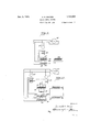
- Fig. 1 shows a wayside block signaling circuit in accordance with the present invention.
- Fig. 2 shows a similar circuit in which a full block overlap is obtained.
- Figs. 3 and 4 show modiiications in which only a one section overlap is obtained.
- Figs. 5, 6, 7 and 8 show the application of the invention to similar systems, except that the inductor device is of the type which contains al tripping induetor and a resetting inductor.
- Fig. 9 is a schematic showing of the train carried devices and the manner of cooperation of same with a roadside device where the roadside device is o't the single inductor type.
- Fig. 1() is a schematic device of the train carried devices and their manner of coopera-v tion with the roadside device when the roads side device is of the double inductor type, namely of the type that has a tripping inductor and reset inductor.
- Fig.- 1 shows a block signaling system which is modified in accordancewith the present invention.
- A In order to malte the diss closure more readily intelligible, some o t the duplicate devices have been eliminated, but i-t will be understood that the devices shown at the entrance to the block are duplicated at the entrance of every other block ⁇ and that the battery pole changer and other vconnections shown at theopposite end of the block are' also duplicated ajt the corresponding end of other blocks.
- y l the devices shown at the entrance to the block are duplicated at the entrance of every other block ⁇ and that the battery pole changer and other vconnections shown at theopposite end of the block are' also duplicated ajt the corresponding end of other blocks.
- B2 represents the wayside inductor which is normally close-circuited by means of the wire 16', relay Contact 17, wire wire 18, switch contact SC and wire 19'.
- YThe switch Contact SC ismechanically or otherwise operable by the semaphore 2, which is capable of assuming clear, caution and: stop positions. As shown vinthe drawings, the semaphore is in the clear position. ⁇ l/Vhenit assumes the caution position the switch contact SC will move to dotted line' position P1, and will remain in circuit with the wire 191 by 4the aidoi conductora@ Wvhen the semaphore 2 assumes' its stop position the switch Contact SC will take position P2, whereby the circuit of the inductor device B2 is broken.
- the operation of the semaphore is controlled by the control relay ⁇ GR.
- Vilhile any suitable type of relay may be used ⁇ torthis purpose, in the present disclosure apolarizedr relay is shown. This relay is designed to operate unpolarized contacts 17 and 2O and the polarized Contact 2:1. IVhen the relay CR is energized by a curren of a Lgiven polar-sV lic ice
- a battery B1 for energizing the control relay CR is disposed and it is provided with a pole changer PC, which is operable by the move ments of the semaphore 1.
- the battery B1 is connected to the control relay CR by means of the conductor 15 and common wire CW on one side and by means ot the conductor 3, track relay Contact 11, conductor 5, track relay contact 6, conductors 7 and 8, inductor PL, conductor 9, track relay contact 11, conductors 12 and 13 on the other side.
- one of the contacts 4, 6, or 11 will be open by the deenern'ization ot one ot the track relays and the semaphore 2 will remain at stop.
- the inductor PL is connected to the block si,Qns-.ling ⁇ circuit at a point between two adjacent track relays.
- a 'con denser K is connected by conductor 10 between one side ot the inductor and the common wire CTN.
- the inductor PL shown diagrammatically in Fig. 1. the specific construction ot which is more clearly explained in the applications and pateuit ⁇ referred to hereinabove, is so designed and constructed that when its circuit is closed, it will be ineffectual, will not transmit any signal and will not operate any devices carried by the train. lt, however, the circuit in which the inductor PL is con nected is open and a train carrying' cooperating, ⁇ devices should pass over this inductor when its circuit is open, an application ot the brakes or some other indication will take place on the train..
- the circuit of the control relay CR is opened either at contact L1 or at contact 6, or at both. rllhe cir iit of the inducsoi. PL, how ver, remains closed through wire 9, contact 11, wires 12 and 13, batt-ery Bl, wires 15, CW and 10, and the condenser, provided, however ⁇ r that the remainder ot the block is clear and the signaling circuit to the end of the block is intact.
- the train therefore, when it approaches and passes inductor PL will receive no indication and will be able to proceed. But should the remainder of the block bev occupied, or should the remainder of the block signal circuit beopen for any other reason, the circuit traced above for the inductor PL would be open at 11 and the pflSS- Y ther in the block.
- the system shown in Fig. 2 is identical with the system shown in Fig. l, so far as the block signaling system 1s concerned and it is, therefore, thought unnecessary to duplicate all of the detail shown in Fig. 1. It is thought sufficient merely to indicate wherein the system shown in Fig. 2 differs from that shown in Fig. 1.
- the condenser K in this system instead of being connected directly to one side of the inductor PL, is connected to the back contact of the track relay armature 6 by wire 2G and to the wire CV by wire 10.
- An inductive resistance 22 is inserted in the circuit in the place of the wire 13 shown in Fig. 1.
- the inductive resistance 22 and the condenser are so chosen that, together with the inductor PL they constitute a circuit which is resonant at the frequency of the current employed by the train carried devices.
- the deenergization of the track relay TB will cause the contact 6 to close the circuit of the condenser, thereby establishing a resonant circuit, or a circuit of low resistance to the alternating current carried by the train devices. If, therefore, the remainder of the block is clear, and if also the block next succeeding is clear, the circuit of the inductor PL is closed and the pass-ing train Will not receive any indication. If, however, there should be a train ahead of the passing train in the remainder of the block, the circuit of the inductor' PL will be opened at the track relay contact 11 and the passing train will receive a stop indication.
- the inductor PL is responsive not only to the conditions that exist in the remainder of the block, but is also responsive ner of connection of the inductor PL is again Tn the present Case one side of the inductor PL .is connected to the return wire modified.
- the approach of a train to the inductor PL will, as in the system described in Fig. 2, establish an alternating current circuit for the inductor PL, which will include the parallel circuit which contains the inductive resistance 23 and the battery in one arm and the condenser 24- and the track relay armature 29 in the other arm.
- the inductive resistance 23 and the condenser 24 are so chosen that they constitute a circuit resonant to the frequencies used for the train devices. It will be seen that in the present system, as well as in the system described in Fig. 2, the presence of a train in the remainder of the block ahead of inductor PL, will cause the opening of track relay contact 11 and thereby break the circuit of the inductor PL.
- the system shown in Fig. i accomplishes the same ends as that shown in Pig. 3, but in a different manner.
- the condenser here is connected to the back contact of the armature 6, while at the battery connection there are two duplicate inductive resistances 131 and 127, one of which is connected in lieu of the wire 13 shown in Fig. 1, and the other of which is connected to the front contact of the track relay armature 29, the armature 29 being controlled by track relay TD (see FiO. 1). Tn the present case connections are so arranged that only one of the inductive resistences remains in the circuit, depending upon whether the battery is connected to the block signaling circuit in one direction or in the other.
- the track relay contact 29 is opened by the presence of a train in the first section of the next succeeding block, both of the inductive resistances are removed from the circuit, with the result that the resonant condition of the circuit is disturbed, this having the same effect as the opening of the circuit.
- the inductor PL will give a stop indication on the passing train when there is a train in the remainder of the block or in the first section of the next succeeding block.
- the A. C. circuits of the inductor PL may be traced as follows: Assume that there is a train in section B of the block. The armature G is therefore closed on its back contact and the'circuit is closed between 6 and 26. We will now assume the conditionsf (1) where there is no train vin the remainder of the block and no train in the next succeeding block: (2) where there is a train in the next succeeding block but at points beyond the iirst section thereof: where there is a train in the ⁇ first section of the neil, succeeding block and where there is a train in the remainder of the block of signal 2.
- the inductive resistances 22, 23, 127 and 131 which are utilized in Figures 2, 3 and L1, are such that they do not interfere with the operation of thecontrol relay CR.
- the system shown in Fig. 5 is substantially identical with that shown in Fig. 2, except for the substitution of the double element type of inductor in the place of the single element type of inductor.
- this type of inductor cach element has its function, one of them (T with a suitable exponent) being known as a trip inductor and the other (R with a suitable exponent) being known as a reset inductor.
- T with a suitable exponent being known as a trip inductor
- R with a suitable exponent
- the function of these tripping and resettinginductors will become clearer hereinafter particularly with the description ofthe combination apparatus sh own in Pig. 10 of the drawings.
- the block signaling ⁇ system per se as shown in this ligure is identical with that shown in Figure 1 and the same reference characters are utilized in order to clearly indicate the identity of the two systems.
- an inducter which is composed of tne two elements R3 and T3.
- T3 is the trip element and is so de :ined that it operates with train carried de ices to effect an application of the brakes and to give a danger indication on the train when the semaphore 2 is at stop position.
- the element P3 of this inductor is the rese element and is designed to cooperate with train carried devices to give a clear indication on the train or to reset the train devices that might have been previously operated by a trip inductor.
- the in-ductors R2 and T2 operate in the same way.
- the inductors R2 and T2 Cil will give a danger indication on the train or will eiiect an application of the brakes it there is a train on the track anywhere between ther inductor and the other end of the neXt succeeding block. If the remainder of the block and the neXt succeeding block are clear the reset inductors will serve to give a clear indication on the train. y
- the inductor is connected to the block signaling circuit in the same manner in which the correspond ing inductor is connected to theblock signaling circuit as shown in Figure 4.
- the inductive resista-noos utilized in the system shown in the other Afigures the system in Fig. 7 utilizes resistance 41, which may or may not be inductive. This resistance is connected bctween wire 141 and the back contact of 29 and is inserted into the circuit for the purpose of putting the circuit in the stop condition.
- the condenser in the present system is so chosen that the inductor circuit will give a clear indication to the passing train when it is free of resistance.
- This normal inductor circuit may be traced as follows and is coinpleted when a train approaches the iuductor: Beginning with the inductor R2, the ⁇ circuit passes through wire 7, contact 6, wire 26, condenser I, conductor 10, return Wire CIV, wire 15, pole changer PC, battery, wire 12, contact 11, wire 9 and inductor T2. The presence of a train in the last section of this block will open contact 11 and the inductors will give al stop indication on the train.
- the two elements of the inductor are connected in the manner shown so that its circuit is closed by the back Contact 6 when the train ⁇ appreaches the inductor.
- the control relay CR is energized from battery B1, through pole changer PC, conductor 113, relay RS, conductors 32 and 12, contact 11, conductor 9, inductor coils T2 and R2, conductor 7, front contact 6, conduct-or 5, con-r tact 4, conductor 3, coil CR, conductor CW, back contact 301, changer PC.
- relay RS Normally the amount of current How-ing in this circuit is insuiicient to energize relay RS.
- a train approaching the inductors R2 and T2 causes the front contact of 6 to open and the back contact of 6 to establish a circuit, from' which the control relay C has been removed.
- the current in the circuit is increased and the relay RS then becomes energized to close the contact 312 and front contact 301.
- the A. C. circuit for the inductors is opened at 312, but the circuit for the control relay CR is closed at back contact 301. Deenergizing of the relay RS and the opening of the inductor circuit does not interfere with the operation of the clock signaling system. It will be seen, therefore, that the presence of a train in the first section of the next succeeding block will put the inductors in a stop indication position.
- F ig.. 9 is a diagrammatic showing of the train carried device which cooperates with the type of roadside inductor shown in Figs. 1 to 4.
- PL is a diagrammatic showing of the roadside inductor shown in Figs. 1 to li.
- the train carries a source of alternating current60and the inductors 61,62.
- the inductor 62 has a winding 63 which is connected to the element 64 of a trip relay.
- the trip relay also includes the normally energized elenient 65.
- the inductor 61 has a winding 66 which is connected to the source 60. Vinding 67 which links the inductor 62 is iny series with the winding 66.
- Vinding 67 which links the inductor 62 is iny series with the winding 66.
- the operation of the system is as follows:
- the inductors 61 and 62 are carried by the train in such a manner that they pass over wayside inductor PL in close proximity therewith when the train passes the inductor.
- the train carried system will remain unaffected if the winding of the inductor PL is close circuited. If the winding of PL is open circuited or if the resistance of the circuit is very high, the electromag netic relationships of the train carried elements will be disturbed and the trip control relay will operate to effect an ,application of the brakes or give some other indicationof danger.
- the vehicle carried coils 61 and 62 form coupled magnetic elements, the coil 61 normally defining an energizing coil receiving energy from the alternator 16 and the coil 62 deiining an energy receiving coil receiving energy from coil 61 through the inductive gap therebetween for correspondingly energizing the relay element 64.
- These coils are in effect a transformer; and when the coupled coils or transformer combination move over the roadside winding PL with the latter in open circuit, magnetic flux is shunted from the secondary coil 62, the flux path now being more intensively from the core of the coil 61 to and through the roadside core or magnetic element over which PL is wound.
- Fig. 10 shows the train carried devices designed to cooperate with the type of roadside inductor shown in Figs. 5 to 8, inclusive.
- This system includes everything shown in Fig. 9 and designed to cooperate with the trip inductor T3.
- the system includes additionally the reset control relay 70, 71, and the inductor 72.
- the inductor 72 is provided with a winding 7 3 which is connected to the winding 70.
- the inductor 72 also has a winding 7 4 which is in series with the inductor and condenser being preferably so chosen that they constitute a resonant circuit.
- the devices 7 O to 75 cooperate with the roadside reset inductor R3 so that when the circuit of R3 is closed in resonant condition, energy having its source in the generator 60 is reflected and transmitted from the vehicle coil 66 to roadside inductor T3 to inductor R3 to the vehicle reset inductor 7 3. Then the circuit to R3 and T8 is open, T8 forms a tripping element cooperating with the coils 61 and 62 in the same manner as hereinabove described in connection with Fig. 9 of the drawings; and under this condition R3 does not perform a resetting function.
- T3 does not trip the vehicle carried circuits but forms an energy receiving coil reg DCving energy from the vehicle transmitting coil 66, said energy being transmitted to the resetting coil R3 which in turn cooperates with the vehicle carried energy receiving coil 73, the latter functioning to reenergize the relay winding 70.
- T claim l In a train controlled block signaling system of the type having a normally closed electric circuit energized by direct current' disposed on the roadside substantially the en tire length of each block for operating the block signals, an inductor connected to an intermediate point of said circuit adapted to cooperate with corresponding alternating current devices carried by a train to give an indication on the train of the condition of the remainder of the bloclr, and means whereby an alternating current circuit is established Cil for the said inductor when a train reaches the vicinity of said inductor. ⁇ Y
- a train controlled block signaling system of the type having an electric circuit normally energized by direct current disposed on the roadside substantially the entire lengtn of each block for operating the block signals, an inductor 'connected to an intermediate point ot said circuit adapted to cooperate with corresponding alternating current devices carried by a train to give an indication on the train of the condition of the remainder oic the block, means whereby an alternating current circuit is established for the said inductor when a train reaches the vicinity ol the said inductor, and means whereby the constants ci the said alternating current circuit may be al* tered by the presence of a train in the remainder of the block.
- a train controlled block signaling system of the type having an electric circuit normally energized by direct current disposed on the roadside substantially the entire length ot each block for operating the block signals, an inductor connected to an intermediate point of said circuit adapted to cooperate with corresponding alternating current devices carried by a train to give an indication on the train of the condition oit the remainder of the block, means whereby an alternating current is established for the Said inductor when a train reaches the vicinity ot ⁇ the said inductor, and means whereby the constants of the said alternating current circuit may be altered by the presence of a train in the block ahead.
- each block for operating the blocl signals, an inductor connected to an intermediate point of said circuitadapted to cooperate with corresponding alternating current devices carried by a train to give an indication on the train of the condition ot the remainder oi: the block, means whereby an alternating current circuit is established for the said inductor when a train reaches the vicinity of the said inductor, and means whereby the. lastmentioned Icircuit may be altered to citer a high resistance to alternating.; ⁇ currents by the presence of a train at any point between the said inductor and the farther end of the next succeeding block.
- a train controlled block signaling ,system of the type having an electric circuit normally energized by direct 'current disposed on the roadside substantially the entire length of each block for operating the block signals, an inductor connected to an intermediate pointot said circuit adapted to cooperate with corresponding alterating current devices carried by a train to give an indication on the train ci the condition ot the remainder of the ence ot a train in advance of the inductor at any point between the inductor and the 4a-rf ⁇ g ther end ot' the next succeedinY block.
- a train controlled bloeitv signaling system of the type having an electric circuit normally energized by direct current disposed on the roadside substantially the entire length of each block for operating the block signals, an inductor connected to an intermediate point oi said circuit adapted to cooperate with corresponding alternating current devices carried by the train to give Aan indication on the train, means whereby an alternating cur'- rent circuit ot' low resistance is established for the said inductor when a train reaches the vicinity of the inductor, and means 'whereby the said la st mentioned circuit may be altered to otter a high resistance to alternating cur rent by the presence of a train in the remainder of the block.
- a train controlled block signaling sys ⁇ tem of the type having an electric circuit normally energized by direct current disposed on the roadside substantiallythe ent-ire length oit' each block-*tor operating the block signals, an inductor connected to an intermediate pointof said circuit adapted to cooperate with corresponding alternating current devices carried by the train to give an indication on the train, means whereby an alternating current circuit of lowresistance is established for the said inductor when a train reaches the vicinity of the inductor, and means whereby the said last mentioned circuit may be altered to offer hight resistance zto alternating cur# rent by the presence of a train at any point between the inductor andthe further end of the next succeeding block.
- a train controlled block signaling system of the type having an electric circuit normally energized by direct current disposed on the roadside substantially the entire length of each block for operating the block signals, an inductor connected to an intermediate point of said circuit adapted to co-V operate with corresponding alternating curs rent devices carried by the train to give an indication on the train, means whereby an alternating current circuit of low resistance is established for the said inductor when fa reaches the ⁇ vicinity of the inductor, and means whereby the said last mentioned circuit may be altered to offer a high resistance to alternating current by the presence of a train at any 4point between the inductor and a point intermediate the ends of the next succeeding' block.
- a train controlled block signaling system of the type having a normally closed electric circuit energized by direct current disposed on the roadside substantially the entire length of the block for operating the block signals, an inductor connected to an intermediate point of said circuit and adapted to cooperate with corresponding alternating current devices carried by the train to give an indication on the train of the condition of the circuit.
- a train controlled block signaling system of the type having a normally closed electric circuit energized by direct current disposed on the roadside substantially the entire length oit the block for operating the block signals, an inductor connected to an intermediate point oi' said circuit and adapted to cooperate with corresponding alternating current devices carried by the train to give an indication on the train of the condition of the circuit, and means whereby an alternating current circuit is established for the said inductor when a train reaches the vicinity of said inductor.
- a train controlled block signaling system of the type having a normally closed electric circuit energized by the direct current disposed on the roadside substantially the entire length of each block for operating the block signals and having a pole reversing switch operable by the operation ot the block signal, an electroresponsive device connected to an intermediate point ot said circuit and adapted to cooperate with corresponding alternating current devices carried by the train to give an indication on the train, means whereby an alternating current circuit of low resistance is established tor t-he said electroresponsive device when a train reaches the vicinity ot said device, and means whereby the operation of the said polarity reversing device converts said alternating) ⁇ current circuit into a high resistance ircuit.
- a train controlled block gnaiing system of the type having an electric circuit substantially the entire length of each bloclr for operating the bloclr signals, an electroresponsive device connected to an intermediate point of said circuit and adapted to cooperate with corresponding alternating cnrrent devices carried by the train to give an indication on the train, means whereby a resonant circuit is established for the said electro-responsive device when a train reaches the vicinity of said device, and
- a train controlled block signaling system of the type having an electric circuit substantially the entire length of each block for operating the block signals, an electroresponsive device connected to an intermediate point of said circuit and adapted to cooperate with corresponding alternating current devices carried by the train to give an indication on the train, means whereby a resonant circuit is established for the said electro-responsive device when a. train reaches the vicinity of said device, and means whereby the resonance of the circuit is destroyed by the presence of a train at any point between the said electro-responsive device and the further end of the next succeeding block.
- a train controlled block signaling system ot the type having an electric circuit substantially the entire length of each block for operating he block signals, an electroresponsive device connected to an intermediate point ot' said circuit and adapted to cooperate with corresponding alterna-ting current devices carried by the tra-in to give an indication on the train, means whereby a resonant circuit is established for the said electro-responsive device when a train reaches the vicinity of said device, and means whereby the resonance of the circuit is destroyed by the presence of a train at any point between the said electro-responsive device and a predetermined point intermediate the ends of the next succeeding block.
- a roadside circuit comprising a source or energy and a. plurality of switches, an
- a train controlled block signaling system or the type having a semaphore signal, and control relay :tor said signal at the entrance to each block, a battery at the other end of the block, a normally closed circuit connecting the battery and the control relay, roadside devices responsive to the presence et train in the bloclr for opening said circuit, and means responsive to the presence of a train in the next succeeding block for reversing the connection of the battery to the circuit, in combination with an electroresponsite device, adapted to cooperate with train carried devices to give an indication on the train, said device being installed on the roadside at a point intermediate the ends o-the block and connected to the circuit at the point of its installation, an inductance connected to said battery in the said circuit, a capacitance Connected to said circuit, and meanswliereby the presence of a train in the vicinity of the device will establish an A. C. circuit through the device, the capacitance and the inductance.
- a train controlled block signaling system of the type having a normally closed circuit extending substantially the entire length of each block, an electroresponsive device connected to an intermediate point of said circuit adapted to cooperate with train f carried devices for giving an indication on the train, a control relay in the said circuit for controlling the operation of the block signals, a normally unenergized signal relay in the said circuit, means controlled by the presence of a train in the block in the vicinity of the said device for deenergizing the con trol relay and energizing the signal relay, a capacitance, and means operated by the energization of the signal relay for electrically connecting said capacitance to said device.
Description
Nov. 5, l 9129.
. G. sHAvER 1,734,603
` TRAIN CONTROL SYSTEM Filed July 4'19, 1926 SSheets-Sheet l @L i N Arclwbalol G. Shvel abbozweqs Nov. 5, 1929. A, G SHAVER 1,734,603
TRAIN CONTROL SYSTEM Filed July 19, 1926 5 Sheets-Sheet 2 Arclbavlcl G. Shaver www@ @1R01 naw: I
NOV. 5, 1929. A G SHAVER 1,734,603
TRAIN CONTROL SYSTEM Filed July 19, 1926 5 Sheets-Sheet 5 E11/wanton Archbakl G. Shaver ,A 1' @M W @wozu/0,115
Patented Nov. 5, 1929 UNITED STATES Param ori-ics ARCHIBALD G. SHAVER, OF CHICAGO, ILLINOTS, ASSGNOR TO THE REGAN SAFETY DEVICES COMPANY, ING., OF NEW YORK, N. Y1, A. CORPORATION OF NEW YORK TRAIN-CONTROL SYSTEM Application filed July 19,
This invention relates broadly to an improvement in train controlled signaling systems. One of the objects of the invention is to provide a device at an intermediate point in the block which cooperates with train car- `ried devices to give desired indications on the train. This object is accomplished in the present system Without the use of any additional line Wiring, the device being connected to the roadside block signaling circuit.
There are a great number of conditions under Which the basic element of the present invention finds useful application. Only a limited number of such applications are illustrated in the present application, and other manners of applying the present invention to various practical conditions will be apparent to any person skilled in the art.
For the purpose of facilitating the understanding of the invention I shall describe hereinafter in general terms the various uses of the invention and the manner of its application under certain specific conditions, and shall describe it in more specific terms in a later portion of the application in cons junction With the drawings appended here- With.
In the broad outlines the block signaling system disclosed herewith comprises a semaphore capable of assuming clear, caution and stop positions and disposed at the entrance to each block. The operation of the semaphore is controlled by a block signaling circuit Which is disposed on the roadside and extends substantially the entire length of the block. This circuit contains a control` relay which controls the operation of the semaphore, the semaphore and relay being disposed at the entrance to the block. A source of energy` such as a battery is disposed at the further end of the block and is connected to the con-i trol relay by means of Wires extending substantially the entire length of the block. Af plurality of normally energized relays andy Which are successively deenergized by the progress of a train in the block, control a series of make and break switches in the circuit con-s necting the battery and the control relay. Ao device designed to cooperate with train car-` 1926. Serial No. 123,335.
ried devices for the automatic application of the brakes or for otherwise giving a danger.` indication on the train by cooperation Withsuch train carried devices, is disposed in the. roadside in the vicinity of the semaphore signal. This device may be of such a. nature and is preferably so controlled by the semaphore that when the semaphore is in a clearv or in a caution position no indication is given: on the train, but an indication is given on the train when the semaphore is in stop position, r it may be so constructed that it will give a clear indication on the train when the semaa phore is in clear or caution position, but Will. give a stop indication as by elfectuating the application of the brakes or otherwise when the semaphore is in the stop position.
iVhen the train operator reaches the entrance of a black having its semaphore set at a. stop position, and if the operator attempts to enter the block against the stop signal the automatic device described above ivill effectuate the application of the brakes on the train, or Will otherwise indicate danger to the operator Within the line of his vision. Under some conditions, however, it becomes desirable for the operator to enter the block against the stop signal While traveling cautiously at a loW rate of speed. For this purpose the train is provided with a manual resetting device whereby the operator may reset the train carried devices or the train carried braking devices to normal position While moving at a restricted speed. Tt is, however, frequently desirable, after the train has progressed some distance Within a block, that in case the danger or stop conditions still persist in the remainder of the block the brakes be again automatically applied or some other danger indication be given on the train to the operator. Tt is, therefore, the object of this invention to provide a device at some point intermediate the ends of the block, whereby if the danger conditions still persist in the remainder of the block, the brakes be automatically applied or some other danger indication be given on the train. vWhile any one of a number of devices to accomplish this purpose may be used, the applicant preT [iii conditions in the next succeeding block.
fers to install at an intermediate point oi the block, a device which is a duplicate of the automatic device that is disposed in the roadside at the entrance to the block. In the speciiic form of the applicants invention, disclosed in the present application, the type of automatic devices utilized are of the type known as inductors. This type ofdevice is broadly disclosed in U. S. Patents Nos. 888,- 416 and 388,417, The specific' construction ot' the train carried devices that cooperate with the Wayside inductors, and their manner of cooperation, are disclosed in my Patent No. 1,552,962, in my co-pending application, Serial No. 506,595, filed October 10, 1921, and my application filed on even date herewith Serial` No. 123,334.
There are al@` other conditions under which it frequently becomes desirable to pr vide an automatic train stopping device at a point intermediate the ends of a block, such conditions arising in the vicinity ot had curves or at the approach to the entrance ot a tunnel or the' like. the train carried devices may be speed controlled, soy that the automatic stopping of the train will not take place unless the speed of the train exceeds a predetermined maximum.
Whereas the wayside induetor, which is disposed at the entrance of a block, is connected ina circuit which, although controlled by the bloc-k signaling circuit, is nevertheless separate and distinct from suoli circuit, the
.2 inductor that is disposed intermediate the ends of the block, is connected directly to the block signaling circuit at the point where said device is installed, and thereby it becomes unnecessary to duplicate any line wires.
Under some conditions it becomes desirable to provide for an overlapping relationship between adjacent blocks. In other Words', it frequently becomes desirable to brin-'g about an application of the brakes on l a train in one block when certain conditions exist in the next block in advance, or in a portion of the nent block in advance. The present invention may, therefore, be utilized to accomplish this end. In the syst-em shown in Fig. 2 the inductor, disposed at an intermediate point of the block, is responsive to the In the system shown in Figs. 3 and 4, the intermediate inductor is responsive to conditions which exist in the first section of the next succeeding block.
While there areV various types of inductor devices available to accomplish the function desired, the applicant prefers to use the type of inductor device which cooperates with train carried deviceswhich are fed by alternating. current. It thereby becomes possible` toestablish circuits i'or the wayside inductor which will permit the passage of alternating f currents, but will not permit the passage of Under such conditions the direct current employed in the block signaling circuits.
In the drawings:
Fig. 1 shows a wayside block signaling circuit in accordance with the present invention.
Fig. 2 shows a similar circuit in which a full block overlap is obtained.
Figs. 3 and 4 show modiiications in which only a one section overlap is obtained.
Figs. 5, 6, 7 and 8 show the application of the invention to similar systems, except that the inductor device is of the type which contains al tripping induetor and a resetting inductor.
Fig. 9 is a schematic showing of the train carried devices and the manner of cooperation of same with a roadside device where the roadside device is o't the single inductor type.
Fig. 1() is a schematic device of the train carried devices and their manner of coopera-v tion with the roadside device when the roads side device is of the double inductor type, namely of the type that has a tripping inductor and reset inductor.
Fig.- 1 shows a block signaling system which is modified in accordancewith the present invention. A In order to malte the diss closure more readily intelligible, some o t the duplicate devices have been eliminated, but i-t will be understood that the devices shown at the entrance to the block are duplicated at the entrance of every other block `and that the battery pole changer and other vconnections shown at theopposite end of the block are' also duplicated ajt the corresponding end of other blocks. y l
At this point I shall explain the diagram` matic showing of someA of the elements of the system. The construction of the remainder, oit the system will be apparent when the op.
eration of the system is described herein-v after. B2 represents the wayside inductor which is normally close-circuited by means of the wire 16', relay Contact 17, wire wire 18, switch contact SC and wire 19'. YThe switch Contact SCismechanically or otherwise operable by the semaphore 2, which is capable of assuming clear, caution and: stop positions. As shown vinthe drawings, the semaphore is in the clear position. `l/Vhenit assumes the caution position the switch contact SC will move to dotted line' position P1, and will remain in circuit with the wire 191 by 4the aidoi conductora@ Wvhen the semaphore 2 assumes' its stop position the switch Contact SC will take position P2, whereby the circuit of the inductor device B2 is broken. y
The operation of the semaphore is controlled by the control relay` GR. Vilhile any suitable type of relay may be used `torthis purpose, in the present disclosure apolarizedr relay is shown. This relay is designed to operate unpolarized contacts 17 and 2O and the polarized Contact 2:1. IVhen the relay CR is energized by a curren of a Lgiven polar-sV lic ice
' be set at stop in the same manner.
ity, all of its contacts are closed and the semaphore is thereby maintained in clear position. 1When the control relay CR is energized by a current of opposite polarity the contacts 17 and 2() will be closed, while the contact 2l will be open and thereby the semaphore will be maintained in the caution posit-ion. lVhen, however, the control relay GR is entirely deenergized all of its contacts 17, 2O and 21 will be open and the semaphore will be moved to stop position. lt will be understoodl that standard control circuits for semaphone operation are utilized and have theretore not been described in detail.
At the opposite end of the block a battery B1 for energizing the control relay CR is disposed and it is provided with a pole changer PC, which is operable by the move ments of the semaphore 1. The battery B1 is connected to the control relay CR by means of the conductor 15 and common wire CW on one side and by means ot the conductor 3, track relay Contact 11, conductor 5, track relay contact 6, conductors 7 and 8, inductor PL, conductor 9, track relay contact 11, conductors 12 and 13 on the other side.
I do not Wish to be limited to the specilic form of the block signaling circuit illustrated and described. Any one of the well known block signaling circuits may he utilized in the place of the one shown herewith. rl`hcspecific block signal circuit shown merely as illustrative ot one type of circuit with which the present invention may be combined without alteringl the operation of the block signals.
In the block sienaling' system illustrated herewith the entry of a train into Jthe block ot signal 2 will open the contact 4 by the deenergization ot the corresponding' track relay TA; the control relay CR will be deenergized thereby, the semaphore 2 will be put in its stop position, and the circuit ot the inductor B2 will be opened at 17 and at SC. A train attempting* to enter the block against thestop signal will have its brakes applied by the effect ot the open circuited inductor B2. As long as there is a train in the block in any one of the sections A, B or C, one of the contacts 4, 6, or 11 will be open by the deenern'ization ot one ot the track relays and the semaphore 2 will remain at stop.
Then the train enters section l) ot the next succeeding,- block the semaphore 1 will The movement ot the semaphore 1 will shiiit the pole changer to its dotted line position, wire linow serving,` in place oi wire 13. The contacts 4i, 6 and 11 being closed, the control relay CR is now again energized, but in the opposite direction. Armaturesx 17 and 2O will be closed, but Contact 21 will remain open. Signal 2 will, therefore be put in its caution position and the circuit of inductor B2 will be closed.
lllhen the train passes out ot the block oiE signal 1, the signal 1 will be moved to its caution position, which movement will shift the pole changer back to its normal position and the control relay CR will again be ener- `sized in its normal direction and the contact 21 will be closed, which 'ill cause the signal 2- to take its clear position.
llllhile in Fig. 1 ot the drawings the signal 1 is shown as controlling` the pole changer PC and the signal 2 as controlling the circuit closer SC, it will be understood that when the system ot the invention is applied to a plurality of successive blocks, each signal or semaphore element will control both a oircuit closer such as SC and a pole changer such as PC.
The inductor PL, it will be noted, is connected to the block si,Qns-.ling` circuit at a point between two adjacent track relays. A 'con denser K is connected by conductor 10 between one side ot the inductor and the common wire CTN.
The inductor PL shown diagrammatically in Fig. 1., the specific construction ot which is more clearly explained in the applications and pateuit` referred to hereinabove, is so designed and constructed that when its circuit is closed, it will be ineffectual, will not transmit any signal and will not operate any devices carried by the train. lt, however, the circuit in which the inductor PL is con nected is open and a train carrying' cooperating,` devices should pass over this inductor when its circuit is open, an application ot the brakes or some other indication will take place on the train..
The operation et the system disclosed in Fig. 1 is as follows:
Assume a train to pass from the lett to the ri ght enter the block shown in the ligure; may have entered the block because Vphore 2 indicated clear or caution. lt is also possible that trie operator ot the train may have entered the block against the stop signal by utilizing;` the manual reset as will be seen further hereinafter.
After the train has passed into the block ot signal 2, hut betere reaching* the inductor PL, the circuit of the control relay CR is opened either at contact L1 or at contact 6, or at both. rllhe cir iit of the inducsoi. PL, how ver, remains closed through wire 9, contact 11, wires 12 and 13, batt-ery Bl, wires 15, CW and 10, and the condenser, provided, however`r that the remainder ot the block is clear and the signaling circuit to the end of the block is intact. The train, therefore, when it approaches and passes inductor PL will receive no indication and will be able to proceed. But should the remainder of the block bev occupied, or should the remainder of the block signal circuit beopen for any other reason, the circuit traced above for the inductor PL would be open at 11 and the pflSS- Y ther in the block.
The system shown in Fig. 2 is identical with the system shown in Fig. l, so far as the block signaling system 1s concerned and it is, therefore, thought unnecessary to duplicate all of the detail shown in Fig. 1. It is thought sufficient merely to indicate wherein the system shown in Fig. 2 differs from that shown in Fig. 1. The condenser K in this system instead of being connected directly to one side of the inductor PL, is connected to the back contact of the track relay armature 6 by wire 2G and to the wire CV by wire 10. An inductive resistance 22 is inserted in the circuit in the place of the wire 13 shown in Fig. 1. The inductive resistance 22 and the condenser are so chosen that, together with the inductor PL they constitute a circuit which is resonant at the frequency of the current employed by the train carried devices.
The operation of this system is as follows:
When a train enters a block and approaches the inductor PL, the deenergization of the track relay TB will cause the contact 6 to close the circuit of the condenser, thereby establishing a resonant circuit, or a circuit of low resistance to the alternating current carried by the train devices. If, therefore, the remainder of the block is clear, and if also the block next succeeding is clear, the circuit of the inductor PL is closed and the pass-ing train Will not receive any indication. If, however, there should be a train ahead of the passing train in the remainder of the block, the circuit of the inductor' PL will be opened at the track relay contact 11 and the passing train will receive a stop indication. If there is aV train in the next succeedingblock the connection of the battery B1 Will beV reversed and the inductive resistance 22 will be removed froin the circuit. This will unsettle the resonant condition of the Circuit of the inductor PL, with the result that such circuit will offer a high resistance to the flow of current and its eflfect will be the same as though the circuit were open. A train which will attempt to pass the inductor PL under these conditions will receive a stop indication or an application ofthe brakes.
It will be seen, therefore, that in the system shown in this ligure a full block overlap is attained. The inductor PL is responsive not only to the conditions that exist in the remainder of the block, but is also responsive ner of connection of the inductor PL is again Tn the present Case one side of the inductor PL .is connected to the return wire modified.
CV, Whereas the other side isfconnected to the back contact of the track relay armature 6. At the battery connection the inductive resistance 23 and the condenser 2st are connected in parallel with each other, the condenser 24 being connected in series with the track relay armature 29 by the wires 27 and 28, the armature 29 being connected to 15 by wire 30. The armature 29 is controlled by the first track relay TD of the next succeeding block. y
In the operation of the system disclosed in Fig. 3 the approach of a train to the inductor PL will, as in the system described in Fig. 2, establish an alternating current circuit for the inductor PL, which will include the parallel circuit which contains the inductive resistance 23 and the battery in one arm and the condenser 24- and the track relay armature 29 in the other arm. The inductive resistance 23 and the condenser 24 are so chosen that they constitute a circuit resonant to the frequencies used for the train devices. It will be seen that in the present system, as well as in the system described in Fig. 2, the presence of a train in the remainder of the block ahead of inductor PL, will cause the opening of track relay contact 11 and thereby break the circuit of the inductor PL. A. train attempting to pass inductor PL under such conditions will receive a stop indication or an application of the brakes. Atrain in the first section of the next succeeding block will cause the contact 29 to open by the deenergization of the corresponding track relay TD. This Will unsettle the resonant conditions in the circuit and the circuit of the inductor PL will then offer a high resistance to the flow of alternating current and put it ina virtually open circuit condition. conditions a train that may attempt to pass the inductor PL will also receive a stop indication or an application of the brakes. However, the presence of a train in the next suc# ceeding block beyond the first section of that block, will leave the circuit of the inductor PL undisturbed and it will, therefore, be possible for a train to pass the inductor PL Without receiving any indication. This is due to the fact that the circuit is now so ar.- ranged that the reversing of the polarity of the battery connection does not alter thel con'-V stants of the alternating current circuit Which includes the inductor PL, the nductverey Y Under such fil sistance 23 remaining in the circuit thru the connection by wire 14 and the condenser 24 remaining in the circuit due to the energization of TD.
The system shown in Fig. i accomplishes the same ends as that shown in Pig. 3, but in a different manner. The condenser here is connected to the back contact of the armature 6, while at the battery connection there are two duplicate inductive resistances 131 and 127, one of which is connected in lieu of the wire 13 shown in Fig. 1, and the other of which is connected to the front contact of the track relay armature 29, the armature 29 being controlled by track relay TD (see FiO. 1). Tn the present case connections are so arranged that only one of the inductive resistences remains in the circuit, depending upon whether the battery is connected to the block signaling circuit in one direction or in the other. 1f, however, the track relay contact 29 is opened by the presence of a train in the first section of the next succeeding block, both of the inductive resistances are removed from the circuit, with the result that the resonant condition of the circuit is disturbed, this having the same effect as the opening of the circuit. Tn this system the inductor PL will give a stop indication on the passing train when there is a train in the remainder of the block or in the first section of the next succeeding block.
The A. C. circuits of the inductor PL may be traced as follows: Assume that there is a train in section B of the block. The armature G is therefore closed on its back contact and the'circuit is closed between 6 and 26. We will now assume the conditionsf (1) where there is no train vin the remainder of the block and no train in the next succeeding block: (2) where there is a train in the next succeeding block but at points beyond the iirst section thereof: where there is a train in the` first section of the neil, succeeding block and where there is a train in the remainder of the block of signal 2.
(1) 1When neither the remainder of the block nor the next succeeding bloclr are oc-` cupied the circuit is as shown in the drawings. The circuit is completed from 6 through 7, 8, PL, 9, 11, 12, inductive resistance 131, PC. B1, PC, 15, CW, 10, l, and 26 bach to 6. This circuit contains the inductive resistance and the condenser which tune said circuit to resonance, and PL is therefore vir tually short circuited. Tt will, therefore, transmit no indication to the train.
(2) When there is a train in the nent succeeding block beyond the first section thereof, the pole changer is shifted to the dotted line position and the armature 29 is in its closed position. The circuit is then completed from G through 7, 8, PL, 9, 11, 12, 1111, inductive resistance 1 7, 29, PC, El, 15, UW, 10, K and 26, back to 6. In this circuit, like in the one described in the preceding paragraph, the inductance 27 and the condenser K tune the circuit of PL to resonance. PL is virtually short circuited and it will transmit no indications to the train.
(3) Then the iirst section of the next succeeding block is occupied the circuit traced in the preceding paragraph is broken at 29 and a new circuit is established through the wire 128 on the back contact of 29 whereby both inductive resistances are eliminated. The resonant condition of the circuit is disturbed and the circuit will offer a high impedance to the flow of alternating current of the freuency employed in the train mechanism. nductor PL will therefore behave in the same manner as if it were open circuited and it will under these conditions eilect the application of the brakes on a passing train.
(4) When there is a train in section C of the block the circuit of the inductor PL will be open at 11, and PL will, therefore, effect the application of the brakes on a passing train.
The inductive resistances 22, 23, 127 and 131, which are utilized in Figures 2, 3 and L1, are such that they do not interfere with the operation of thecontrol relay CR.
The system shown in Fig. 5 is substantially identical with that shown in Fig. 2, except for the substitution of the double element type of inductor in the place of the single element type of inductor. In this type of inductor cach element has its function, one of them (T with a suitable exponent) being known as a trip inductor and the other (R with a suitable exponent) being known as a reset inductor. The function of these tripping and resettinginductors will become clearer hereinafter particularly with the description ofthe combination apparatus sh own in Pig. 10 of the drawings. The block signaling` system per se as shown in this ligure is identical with that shown in Figure 1 and the same reference characters are utilized in order to clearly indicate the identity of the two systems.
itt the entrance to the block in place of the inductor B2 of Figure 1 is placed an inducter which is composed of tne two elements R3 and T3. T3 is the trip element and is so de :ined that it operates with train carried de ices to effect an application of the brakes and to give a danger indication on the train when the semaphore 2 is at stop position. The element P3 of this inductor is the rese element and is designed to cooperate with train carried devices to give a clear indication on the train or to reset the train devices that might have been previously operated by a trip inductor. The in-ductors R2 and T2 operate in the same way. Tn this system, therefore, as explained in connection with the discussion of the operation of the system shown in Figure 2, the inductors R2 and T2 Cil will give a danger indication on the train or will eiiect an application of the brakes it there is a train on the track anywhere between ther inductor and the other end of the neXt succeeding block. If the remainder of the block and the neXt succeeding block are clear the reset inductors will serve to give a clear indication on the train. y
In `the system shown in Figure 6 the type of inductor utilized is the same as that uti-` lized in Figure 5, and is connected 'to the block signaling circuit in the manner as shown in Figure 3. The inductive resistance 23 and condenser 24 which are so chosen as to constitute a circuit resonant to the frequency employed in the train carried devices are the equivalents of the corresponding elements 1n Figure 3 and function in the same manner as in Figure 3. In this system as in the system shown in Figure 3, an overlap of only one section is obtained. In other words the press ence of a train in the last section of the block or in the iirst section of the next succeeding block will either break the inductor circuit or destroy the resonance of the circuit by removing the condenser due to the opening ol the contact 29 and thereby the trip element T2 will become eli'ective to cooperate with the train carried devices and eifect an application of the brakes or cause a danger indication.
In the system shownin Figure 7 the inductor is connected to the block signaling circuit in the same manner in which the correspond ing inductor is connected to theblock signaling circuit as shown in Figure 4. In lieu oit the inductive resista-noos utilized in the system shown in the other Afigures the system in Fig. 7 utilizes resistance 41, which may or may not be inductive. This resistance is connected bctween wire 141 and the back contact of 29 and is inserted into the circuit for the purpose of putting the circuit in the stop condition. The condenser in the present system is so chosen that the inductor circuit will give a clear indication to the passing train when it is free of resistance. This normal inductor circuit may be traced as follows and is coinpleted when a train approaches the iuductor: Beginning with the inductor R2, the `circuit passes through wire 7, contact 6, wire 26, condenser I, conductor 10, return Wire CIV, wire 15, pole changer PC, battery, wire 12, contact 11, wire 9 and inductor T2. The presence of a train in the last section of this block will open contact 11 and the inductors will give al stop indication on the train. The presence o1 a train in the first section oi the next succeedingblock will open the front contact 29 and close the back contact 29 and at the same time the pole changer PC will be moved to the dotted line position and the circuit of the inductor will be as follows: the inductoi R2, conductor 7, contact 6, wire 26, condenser K, wire 10, return conductor CW, wire 15,
pole changer PC, battery B1, `pole changer- PC, wire 131, contact 29, resistance 41, Wire 281, wires 141 and 12, contactll, wire 9 and trip inductor T2. The insertion of the resistance 41 into this circuit will have the same effect upon the inductors as opening the circuit, and it will eiiect an application of the brakes or a danger indication on the train. The operation of the control relay CR Will not be aii'ccted by the insertion of the resistance. Under these conditions, however, the inductors will give a stop indication when there is a train in the last section of the block or in the iirst section of the next succeeding block. When, however, there is no train in either of these sections, although there may be a train in the remaining section ofthe next succeedingbloclr, the resetting of the contact 29 to its tlront contact will again remove the resistance 40 from the circuit and the normal circuit of the inductor is reestablished and it will give a clear indication.
In the system shown in `Figure 8, the two elements of the inductor are connected in the manner shown so that its circuit is closed by the back Contact 6 when the train `appreaches the inductor. Normallyv the control relay CR is energized from battery B1, through pole changer PC, conductor 113, relay RS, conductors 32 and 12, contact 11, conductor 9, inductor coils T2 and R2, conductor 7, front contact 6, conduct-or 5, con-r tact 4, conductor 3, coil CR, conductor CW, back contact 301, changer PC. y
Normally the amount of current How-ing in this circuit is insuiicient to energize relay RS. A train approaching the inductors R2 and T2 causes the front contact of 6 to open and the back contact of 6 to establish a circuit, from' which the control relay C has been removed. The current in the circuit is increased and the relay RS then becomes energized to close the contact 312 and front contact 301. This establishes the clear 0pcrating circuit for the inductor R2, T2, to include conductor 9, contactV 11, conductor 12, Contact 29, conductor 15, condenser K, conductor 271, Vfront contact 312, conductors CW and 82, back contact 6, conductor 7 and coils of inductors R2 and T2., In the circuit just traced the condenser K is so `chosen that together with the winding of inductors R2 and T2 the circuit is resonant at the frequency of the current utilized in controlling conductor `142 `and pole train in the first section of the next succeeding block. The presence of a train in the first section of the next succeeding block will open the front Contact 33, the stick circuit just traced will open and RS becomes deenergized. The A. C. circuit for the inductors is opened at 312, but the circuit for the control relay CR is closed at back contact 301. Deenergizing of the relay RS and the opening of the inductor circuit does not interfere with the operation of the clock signaling system. It will be seen, therefore, that the presence of a train in the first section of the next succeeding block will put the inductors in a stop indication position.
F ig.. 9 is a diagrammatic showing of the train carried device which cooperates with the type of roadside inductor shown in Figs. 1 to 4. PL is a diagrammatic showing of the roadside inductor shown in Figs. 1 to li. The train carries a source of alternating current60and the inductors 61,62. 'The inductor 62 has a winding 63 which is connected to the element 64 of a trip relay. The trip relay also includes the normally energized elenient 65. The inductor 61 has a winding 66 which is connected to the source 60. Vinding 67 which links the inductor 62 is iny series with the winding 66. The operation ofthis system is described in the applications and patents referred to hereinabove. v
In broad terms, the operation of the system is as follows: The inductors 61 and 62 are carried by the train in such a manner that they pass over wayside inductor PL in close proximity therewith when the train passes the inductor. The train carried system will remain unaffected if the winding of the inductor PL is close circuited. If the winding of PL is open circuited or if the resistance of the circuit is very high, the electromag netic relationships of the train carried elements will be disturbed and the trip control relay will operate to effect an ,application of the brakes or give some other indicationof danger.
As described more particularly in the applications and pat-ents hereinabove referred to, the vehicle carried coils 61 and 62 form coupled magnetic elements, the coil 61 normally defining an energizing coil receiving energy from the alternator 16 and the coil 62 deiining an energy receiving coil receiving energy from coil 61 through the inductive gap therebetween for correspondingly energizing the relay element 64. These coils are in effect a transformer; and when the coupled coils or transformer combination move over the roadside winding PL with the latter in open circuit, magnetic flux is shunted from the secondary coil 62, the flux path now being more intensively from the core of the coil 61 to and through the roadside core or magnetic element over which PL is wound. This diversion of fluir effects the substantial deenergization of the relay element 64. Tf the roadside inductor PL, however, is close circuited, then the vehicle inductively coupled coils move over the roadside element without a change in effect, that is, without a substantial disturbance or variation in the flux conditions between said vehicle coupled coils 61 and 62.
Fig. 10 shows the train carried devices designed to cooperate with the type of roadside inductor shown in Figs. 5 to 8, inclusive. This system includes everything shown in Fig. 9 and designed to cooperate with the trip inductor T3. The system includes additionally the reset control relay 70, 71, and the inductor 72. The inductor 72 is provided with a winding 7 3 which is connected to the winding 70. The inductor 72 also has a winding 7 4 which is in series with the inductor and condenser being preferably so chosen that they constitute a resonant circuit.
The devices 7 O to 75 cooperate with the roadside reset inductor R3 so that when the circuit of R3 is closed in resonant condition, energy having its source in the generator 60 is reflected and transmitted from the vehicle coil 66 to roadside inductor T3 to inductor R3 to the vehicle reset inductor 7 3. Then the circuit to R3 and T8 is open, T8 forms a tripping element cooperating with the coils 61 and 62 in the same manner as hereinabove described in connection with Fig. 9 of the drawings; and under this condition R3 does not perform a resetting function. Vfhen, however, the series circuit of R3 and T3 is closed, T3 does not trip the vehicle carried circuits but forms an energy receiving coil reg ceiving energy from the vehicle transmitting coil 66, said energy being transmitted to the resetting coil R3 which in turn cooperates with the vehicle carried energy receiving coil 73, the latter functioning to reenergize the relay winding 70.
do not wish to be limited to the form of block signaling circuit disclosed herewith, nor to the form of train carried devices disclosed therewith. These are shown as merely illustrative of the embodiment of my inven` tion.
Having described my invention, T claim l. In a train controlled block signaling system of the type having a normally closed electric circuit energized by direct current' disposed on the roadside substantially the en tire length of each block for operating the block signals, an inductor connected to an intermediate point of said circuit adapted to cooperate with corresponding alternating current devices carried by a train to give an indication on the train of the condition of the remainder of the bloclr, and means whereby an alternating current circuit is established Cil for the said inductor when a train reaches the vicinity of said inductor.` Y
2. In a train controlled block signaling system of the type having an electric circuit normally energized by direct current disposed on the roadside substantially the entire lengtn of each block for operating the block signals, an inductor 'connected to an intermediate point ot said circuit adapted to cooperate with corresponding alternating current devices carried by a train to give an indication on the train of the condition of the remainder oic the block, means whereby an alternating current circuit is established for the said inductor when a train reaches the vicinity ol the said inductor, and means whereby the constants ci the said alternating current circuit may be al* tered by the presence of a train in the remainder of the block.
3. In a train controlled block signaling system of the type having an electric circuit normally energized by direct current disposed on the roadside substantially the entire length ot each block for operating the block signals, an inductor connected to an intermediate point of said circuit adapted to cooperate with corresponding alternating current devices carried by a train to give an indication on the train of the condition oit the remainder of the block, means whereby an alternating current is established for the Said inductor when a train reaches the vicinity ot` the said inductor, and means whereby the constants of the said alternating current circuit may be altered by the presence of a train in the block ahead.
4. In a train controlled block signaling rsystem of the type having an electric circuit nor-l mally energized by direct current disposed on the roadside substantially the entire length oit each block for operating the blocl: signals, an inductor connected to an intermediate point of said circuitadapted to cooperate with corresponding alternating current devices carried by a train to give an indication on the train of the condition ot the remainder oi: the block, means whereby an alternating current circuit is established for the said inductor when a train reaches the vicinity of the said inductor, and means whereby the. lastmentioned Icircuit may be altered to citer a high resistance to alternating.;` currents by the presence of a train at any point between the said inductor and the farther end of the next succeeding block.
5. In a train controlled block signaling ,system of the type having an electric circuit normally energized by direct 'current disposed on the roadside substantially the entire length of each block for operating the block signals, an inductor connected to an intermediate pointot said circuit adapted to cooperate with corresponding alterating current devices carried by a train to give an indication on the train ci the condition ot the remainder of the ence ot a train in advance of the inductor at any point between the inductor and the 4a-rf` g ther end ot' the next succeedinY block.
6. In a train controlled bloeitv signaling system of the type having an electric circuit normally energized by direct current disposed on the roadside substantially the entire length of each block for operating the block signals, an inductor connected to an intermediate point oi said circuit adapted to cooperate with corresponding alternating current devices carried by the train to give Aan indication on the train, means whereby an alternating cur'- rent circuit ot' low resistance is established for the said inductor when a train reaches the vicinity of the inductor, and means 'whereby the said la st mentioned circuit may be altered to otter a high resistance to alternating cur rent by the presence of a train in the remainder of the block.
7 -In a train controlled block signaling sys`` tem of the type having an electric circuit normally energized by direct current disposed on the roadside substantiallythe ent-ire length oit' each block-*tor operating the block signals, an inductor connected to an intermediate pointof said circuit adapted to cooperate with corresponding alternating current devices carried by the train to give an indication on the train, means whereby an alternating current circuit of lowresistance is established for the said inductor when a train reaches the vicinity of the inductor, and means whereby the said last mentioned circuit may be altered to offer hight resistance zto alternating cur# rent by the presence of a train at any point between the inductor andthe further end of the next succeeding block.
8. In a train controlled block signaling system of the type having an electric circuit normally energized by direct current disposed on the roadside substantially the entire length of each block for operating the block signals, an inductor connected to an intermediate point of said circuit adapted to co-V operate with corresponding alternating curs rent devices carried by the train to give an indication on the train, means whereby an alternating current circuit of low resistance is established for the said inductor when fa reaches the `vicinity of the inductor, and means whereby the said last mentioned circuit may be altered to offer a high resistance to alternating current by the presence of a train at any 4point between the inductor and a point intermediate the ends of the next succeeding' block.
9. In a train controlled block signaling system of the type having a normally closed electric circuit energized by direct current disposed on the roadside substantially the entire length of the block for operating the block signals, an inductor connected to an intermediate point of said circuit and adapted to cooperate with corresponding alternating current devices carried by the train to give an indication on the train of the condition of the circuit.
10. ln a train controlled block signaling system of the type having a normally closed electric circuit energized by direct current disposed on the roadside substantially the entire length oit the block for operating the block signals, an inductor connected to an intermediate point oi' said circuit and adapted to cooperate with corresponding alternating current devices carried by the train to give an indication on the train of the condition of the circuit, and means whereby an alternating current circuit is established for the said inductor when a train reaches the vicinity of said inductor.
11. ln al train controlled bloclr signaling system ot the type having a normally closed electric circuit energized by direct current disposed on the roadside substantially the entire length of each block for operating the block signals, an inductor connected to an intermediate point ot said circuit adapted to cooperate with corresponding alternating current devices carried by the train to give an indication on the train of the condition of the circuit in the next bloclr in advance.
12. In a. train controlled block signaling system of the type having a normally closed electric circuit energized by the direct current disposed on the roadside substantially the entire length of each block for operating the block signals and having a pole reversing switch operable by the operation ot the block signal, an electroresponsive device connected to an intermediate point ot said circuit and adapted to cooperate with corresponding alternating current devices carried by the train to give an indication on the train, means whereby an alternating current circuit of low resistance is established tor t-he said electroresponsive device when a train reaches the vicinity ot said device, and means whereby the operation of the said polarity reversing device converts said alternating)` current circuit into a high resistance ircuit.
13. ln a train controlled block gnaiing system of the type having an electric circuit substantially the entire length of each bloclr for operating the bloclr signals, an electroresponsive device connected to an intermediate point of said circuit and adapted to cooperate with corresponding alternating cnrrent devices carried by the train to give an indication on the train, means whereby a resonant circuit is established for the said electro-responsive device when a train reaches the vicinity of said device, and
means whereby the resonance of the circuit is destroyed by the presence of a train in the remainder orn the block.
14. ln a train controlled block signaling system of the type having an electric circuit substantially the entire length of each block for operating the block signals, an electroresponsive device connected to an intermediate point of said circuit and adapted to cooperate with corresponding alternating current devices carried by the train to give an indication on the train, means whereby a resonant circuit is established for the said electro-responsive device when a. train reaches the vicinity of said device, and means whereby the resonance of the circuit is destroyed by the presence of a train at any point between the said electro-responsive device and the further end of the next succeeding block.
15. ln a train controlled block signaling system ot the type having an electric circuit substantially the entire length of each block for operating he block signals, an electroresponsive device connected to an intermediate point ot' said circuit and adapted to cooperate with corresponding alterna-ting current devices carried by the tra-in to give an indication on the train, means whereby a resonant circuit is established for the said electro-responsive device when a train reaches the vicinity of said device, and means whereby the resonance of the circuit is destroyed by the presence of a train at any point between the said electro-responsive device and a predetermined point intermediate the ends of the next succeeding block.
16. In a train controlled block signaling system, a roadside circuit comprising a source or energy and a. plurality of switches, an
s i aiternating current circuit is established for said electro-responsive device by the opening current circuit is broken by the opening of another ot said switches.
17. A train controlled block signaling system or the type having a semaphore signal, and control relay :tor said signal at the entrance to each block, a battery at the other end of the block, a normally closed circuit connecting the battery and the control relay, roadside devices responsive to the presence et train in the bloclr for opening said circuit, and means responsive to the presence of a train in the next succeeding block for reversing the connection of the battery to the circuit, in combination with an electroresponsite device, adapted to cooperate with train carried devices to give an indication on the train, said device being installed on the roadside at a point intermediate the ends o-the block and connected to the circuit at the point of its installation, an inductance connected to said battery in the said circuit, a capacitance Connected to said circuit, and meanswliereby the presence of a train in the vicinity of the device will establish an A. C. circuit through the device, the capacitance and the inductance.
18. The combination recited in claim 17, and means whereby the reversal of the connection of the battery to the block signaling circuit will disconnect the inductance.
19. The combination recited in claim 17, and means responsive tov a train in the first section oi the next succeeding block for disconnecting said capacitance from the said A. C. circuit.
20. In a train controlled block signaling system of the type having a normally closed circuit extending substantially the entire length of each block, an electroresponsive device connected to an intermediate point of said circuit adapted to cooperate with train f carried devices for giving an indication on the train, a control relay in the said circuit for controlling the operation of the block signals, a normally unenergized signal relay in the said circuit, means controlled by the presence of a train in the block in the vicinity of the said device for deenergizing the con trol relay and energizing the signal relay, a capacitance, and means operated by the energization of the signal relay for electrically connecting said capacitance to said device.
21. The combination recited in claim 20, and means responsive to the presence of a train in the neXt succeeding block for dis connecting said capacitance.
Signed at New York city in the county of New York and State of New York, this 25th day of June, A. D. 1926.
ARCHIBALD Gr. SHAVER.
Publications (1)
| Publication Number | Publication Date |
|---|---|
| US1734603A true US1734603A (en) | 1929-11-05 |
Family
ID=3419334
Family Applications (1)
| Application Number | Title | Priority Date | Filing Date |
|---|---|---|---|
| US1734603D Expired - Lifetime US1734603A (en) | Train-control system |
Country Status (1)
| Country | Link |
|---|---|
| US (1) | US1734603A (en) |
-
0
- US US1734603D patent/US1734603A/en not_active Expired - Lifetime
Similar Documents
| Publication | Publication Date | Title |
|---|---|---|
| US1734603A (en) | Train-control system | |
| US2000166A (en) | Railway signal system | |
| US2371568A (en) | Trackway system for train control | |
| US2021951A (en) | Railway signaling apparatus | |
| US1483358A (en) | Railway traffic-controlling apparatus | |
| US2313887A (en) | Railway traffic controlling apparatus | |
| US1822497A (en) | Railway traffic controlling apparatus | |
| US1512288A (en) | Automatic train-control system | |
| US1483980A (en) | Railway-traffic-controlling apparatus | |
| US2152276A (en) | Controlling apparatus for highway crossing signals | |
| US1624118A (en) | Automatic train control | |
| US1679390A (en) | Automatic train-control system | |
| US1824174A (en) | Train control | |
| US2976403A (en) | Railway traffic controlling apparatus | |
| US1797560A (en) | Railway-traffic-controlling apparatus | |
| US2024980A (en) | Railway track circuit apparatus | |
| US1855891A (en) | Railway signaling | |
| US1428894A (en) | Railway-traffic-controlling apparatus | |
| US1592771A (en) | Train control | |
| US1866139A (en) | Automatic train control | |
| US1342873A (en) | Train-controlling apparatus | |
| US1855705A (en) | Highway crossing protection | |
| US2072232A (en) | Signaling system for railroads | |
| US1820170A (en) | Apparatus for the control of highway crossing signals | |
| US1683222A (en) | Track-circuit system |