US1719829A - Method for producing squirrel-cage rotors - Google Patents
Method for producing squirrel-cage rotors Download PDFInfo
- Publication number
- US1719829A US1719829A US159042A US15904227A US1719829A US 1719829 A US1719829 A US 1719829A US 159042 A US159042 A US 159042A US 15904227 A US15904227 A US 15904227A US 1719829 A US1719829 A US 1719829A
- Authority
- US
- United States
- Prior art keywords
- molten metal
- conducting
- squirrel
- ring
- core
- Prior art date
- Legal status (The legal status is an assumption and is not a legal conclusion. Google has not performed a legal analysis and makes no representation as to the accuracy of the status listed.)
- Expired - Lifetime
Links
Images
Classifications
-
- B—PERFORMING OPERATIONS; TRANSPORTING
- B22—CASTING; POWDER METALLURGY
- B22D—CASTING OF METALS; CASTING OF OTHER SUBSTANCES BY THE SAME PROCESSES OR DEVICES
- B22D19/00—Casting in, on, or around objects which form part of the product
- B22D19/0054—Casting in, on, or around objects which form part of the product rotors, stators for electrical motors
-
- Y—GENERAL TAGGING OF NEW TECHNOLOGICAL DEVELOPMENTS; GENERAL TAGGING OF CROSS-SECTIONAL TECHNOLOGIES SPANNING OVER SEVERAL SECTIONS OF THE IPC; TECHNICAL SUBJECTS COVERED BY FORMER USPC CROSS-REFERENCE ART COLLECTIONS [XRACs] AND DIGESTS
- Y10—TECHNICAL SUBJECTS COVERED BY FORMER USPC
- Y10T—TECHNICAL SUBJECTS COVERED BY FORMER US CLASSIFICATION
- Y10T29/00—Metal working
- Y10T29/49—Method of mechanical manufacture
- Y10T29/49002—Electrical device making
- Y10T29/49009—Dynamoelectric machine
- Y10T29/49012—Rotor
Definitions
- This invention relates to induction motors and more particularly to squirrel-cage rotors and to a method of producing the same.
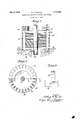
- Fig. 1 is a pictorial section of a rotor taken along its axis of rotation, the upper shortcircuiting ring being finished and the lower short-circuiting ring. being molten and in 2 the process of being welded to the ends of conducting bars.
- Fig. 2 is an' end view of a rotor with half of a short-circuiting ring cut away.
- Fi 3 diagrammatically illustrates av pol- 3o ishe section on line 33 of Fig. 2.
- My method involves obtainm a perfect weld between each end of a conducting bar 10 and the short-circuiting ring 11 with which it is connected.
- a mould, 12f, for a short-cir'cuiting ring 11 is provided or the u ose of receiving the molten metal an givin it its finished form.
- the ends of the con ucting bars 10 are finished into a plurality of points, 13, 14, in order that the molten metal will be pierced in several places thereb insuring a large contacting surface for t e molten metal to effect as well as render it possible for a length 15 of the uncut end of the bar to come into contact with the hot clear metal 16.
- Another and important purpose of the reentrant opening 17 is to provide a positive locking relation between the conducting rod 10 and the short-circuiting ring 11 whereby,
- the positive connection com rises an anchor lug 18 extending from and orming a part of the body portion of shortcircuitin ring 11 and engaging with a conducting ar 10 through the co-relation of the walls of the re-entrant opening 17.
- the re-entrant opening 17 is of sufficient size to permit gas bubbles to gather therein and whatever bubbles might gather would. remain close to the looped inner surface of the confined area and in no way interfere with the formation or effectiveness of the anchor lug 18.
- the method of mahng the squirrel cage 'rotor com rises selecting the desired number of con noting rods 16 and finishing them into lengths having ends of the general character and form already set forth. These bars must then be mounted in such a manner as to support them in the relative positions (Fig. Q) that they are to maintain ultimately. This may be accomplished in any way desired, but in small units it is com mil was
- each bar within its groove or recess 19 in the core 20.
- a suitable tool may be brought to bear upon the rounded wall portion at the base of the re-entrant opening 17 whereby forces may be applied to the bar without causing damage to points 13, 14.
- the core as is well understood, may be made up of laminae and the whole unit may be conveniently handled by the rotor shaft 21 to which the core is fitted. In the eventthat the 'core'20 is not utilized for supportingthe conducting bars, the conducting bars would be adjusted and fitted to the core after one of the short circuitin rings ⁇ ias been cast and welded to the con ucting ars.
- the whole assembly With the conductin bars supported by suitable means, or by t e core, the whole assembly is lowered in a vertical direction until the ends of the conducting rods are immersed within the molten metal 16 within the mould 12 substantially as illustrated in Fig. 1. 'The mould is of such dimensions as to form a short circuiting ring 11. The two points 13 14 of each rod will ierce the surface of themolten metal an will permitthe entry of a bar 10 within the body of the molten metal without producing a substantial derangement in the general pointed outline of the end of a bar.
- Fig. 3 isintended to illustrate, diagrammatically the welded relation of a rod with a ring.
- This illustration shows a polished section taken on line 3-3 of Fig. 2.
- the rod iece and and the section of ring is of one the dotted outline of the end 0 the rod discerns a border line of the two pieces.
- the heat given off by the molten metal has fused the portion of the end of the rod with which the molten metal has come into contact with the result that the general outline of the end of the rod is maintained, though in an altered form and the two members are one and mrods.
- the core is positioned in p ace, if hat step has 'not been completed alread and all of the ends on the other side 0 the core are immersed within a rin of molten metal in the manner described hereinbefore.
- This step of the method is pictorially illustrated in Fig. 1.
- the method of making a squirrel-cage rotor comprising, finishing each end' of a plurality of conducting bars into a plurality of points and a reentrant opening, positioning each bar within a core, immersing all of the ends at one side of the core within a ring of molten metal, connecting the ends of the rods with the ring by cooling action, immersing all of the ends on the other side of the core within a ⁇ ring of molten metal, and connecting the latter ends of the rods with the latter ring by cooling action.
- the material to comprise the second piece into a molten state, immersing into the molten material the portion of the first mentioned piece which is to be welded with the second piece, and permitting the molten material of the second piece to solidi with the said portion of the first mentione piece immersed therein.
- the method of making a squirrel-cage windin comprising, finishing each of the ends 0 a plurality of conducting bars into a plurality of points, mounting said conducting bars in fixed relation to one another, forming a molten metal bath in a mould s0 sha ed as to receive one set of ends of the con ucting bars, .causing thepoints of said one set of ends to enter into the molten metal the end 115. iece of metal'to a molten I by relative movement of the conducting bars and molten metal bath, and permitting the molten metal bath to solidify.
Description
July 9, 1929. A. c. BUNKER METHOD FOR PRODUCING SQUIRREL CAGE ROTORS Filed Jan. 5, 1927 INVENTOR BY MSW HIS ATTORNEYS l atenteil July 9, 192 9. A Q UNITED STATES 1,719,829 PATENT OFFICE.
ARTHUR C. BUNKER, F MONTCLAIR, NEW JERSEY; ASSIGNOR TO CROCKER-WHEELER ELECTRIC MANUFACTURING COMPANY, OF AMPERE, NEW JERSEY, A CORPORA- rron on NEW JERSEY.
METHOD EOE PRODUCING SQUIRREL-CAGE ROTORS.
Application filed January 5, 1927. Serial No. 159,042.
This invention relates to induction motors and more particularly to squirrel-cage rotors and to a method of producing the same.
In the manufacture of rotors of the squirrel-cage type it is desirable to obtain a complete and perfect union of the ends of the.
conducting bars with the short-circuiting rings or collars for the two-fold purpose of obtaining highest conducting efiiciency and maximum strength at the points ofconnection. It is among the purposes of my invention to provide a method by which a rotor maybe obtained whichis characterized by accomplishment of this two-fold purpose and which is productive of an article embodying the most perfect construction of a squirrel-cage conducting frame.
Other objects and advantages will be pointed out hereinafter in the specification and in the drawings, in which:
Fig. 1 is a pictorial section of a rotor taken along its axis of rotation, the upper shortcircuiting ring being finished and the lower short-circuiting ring. being molten and in 2 the process of being welded to the ends of conducting bars.
Fig. 2 is an' end view of a rotor with half of a short-circuiting ring cut away.
Fi 3 diagrammatically illustrates av pol- 3o ishe section on line 33 of Fig. 2.
My method involves obtainm a perfect weld between each end of a conducting bar 10 and the short-circuiting ring 11 with which it is connected. To accomplish this as operation, a mould, 12f, for a short-cir'cuiting ring 11 is provided or the u ose of receiving the molten metal an givin it its finished form. The ends of the con ucting bars 10 are finished into a plurality of points, 13, 14, in order that the molten metal will be pierced in several places thereb insuring a large contacting surface for t e molten metal to effect as well as render it possible for a length 15 of the uncut end of the bar to come into contact with the hot clear metal 16. I have illustrated the plurality of points at one end of a conducting bar in the number of two, which may be of the same or of different lengths, and each end of a single con- 60 ducting bar is finished in a like manner.
The re-entrant o ening 17 out out at the base of the oints as a neck which is relativel sma' er across its throat than the widt of the area immediately within its throat. The edges and walls of the points impair the efliciency of the weld of the uncut immersed portions of the end of the conducting bar with the ring.
Another and important purpose of the reentrant opening 17 is to provide a positive locking relation between the conducting rod 10 and the short-circuiting ring 11 whereby,
should there be any weakness or failure 1n the weld of any one conducting rod, nevertheless there wouldexist a positive and rigid connection between the conducting rod and the ringwhere the particular defective or incomplete weldingexists. Such precaution is desirable because such a condition as the cooling or solidification of one section of a ring at a different time than another section of the ring may occur to the detriment of obtaining a erfectweld of one or more of the ends of t e conducting bars with a ring.
In effect, the positive connection com rises an anchor lug 18 extending from and orming a part of the body portion of shortcircuitin ring 11 and engaging with a conducting ar 10 through the co-relation of the walls of the re-entrant opening 17. As
has been stated hereinbefore, the re-entrant opening 17 ,is of sufficient size to permit gas bubbles to gather therein and whatever bubbles might gather would. remain close to the looped inner surface of the confined area and in no way interfere with the formation or effectiveness of the anchor lug 18. Features of my-invention which concern structural improvements are described and claimed in a divisional application bearing the Serial Number 315,116.
The method of mahng the squirrel cage 'rotor com rises selecting the desired number of con noting rods 16 and finishing them into lengths having ends of the general character and form already set forth. These bars must then be mounted in such a manner as to support them in the relative positions (Fig. Q) that they are to maintain ultimately. This may be accomplished in any way desired, but in small units it is com mil was
venientto fiteach bar within its groove or recess 19 in the core 20. In fitting each bar within a recess 19 a suitable tool may be brought to bear upon the rounded wall portion at the base of the re-entrant opening 17 whereby forces may be applied to the bar without causing damage to points 13, 14. The core, as is well understood, may be made up of laminae and the whole unit may be conveniently handled by the rotor shaft 21 to which the core is fitted. In the eventthat the 'core'20 is not utilized for supportingthe conducting bars, the conducting bars would be adjusted and fitted to the core after one of the short circuitin rings {ias been cast and welded to the con ucting ars.
With the conductin bars supported by suitable means, or by t e core, the whole assembly is lowered in a vertical direction until the ends of the conducting rods are immersed within the molten metal 16 within the mould 12 substantially as illustrated in Fig. 1. 'The mould is of such dimensions as to form a short circuiting ring 11. The two points 13 14 of each rod will ierce the surface of themolten metal an will permitthe entry of a bar 10 within the body of the molten metal without producing a substantial derangement in the general pointed outline of the end of a bar.
Fig. 3 isintended to illustrate, diagrammatically the welded relation of a rod with a ring. This illustration shows a polished section taken on line 3-3 of Fig. 2. The rod iece and and the section of ring is of one the dotted outline of the end 0 the rod discerns a border line of the two pieces. The heat given off by the molten metal has fused the portion of the end of the rod with which the molten metal has come into contact with the result that the general outline of the end of the rod is maintained, though in an altered form and the two members are one and mrods.
7 separable.
For concluding the manufacture of the ulrrelge rotor, the core is positioned in p ace, if hat step has 'not been completed alread and all of the ends on the other side 0 the core are immersed within a rin of molten metal in the manner described hereinbefore. This step of the method is pictorially illustrated in Fig. 1. The care incldent to the proper carrying out of this step of the process is the same as has been described in the casting and welding of the first ring to the other ends of the conducting I am aware that the principles of my method may be utilized in many ways, for example, without assembling or making the core until the conducting frame comprising the conducting bars and short-circuiting rings is completed, and that the ends of the conducting bars may be finished in a modi-.
the first name fied form other than that specifically illustrated or described. I
For these and other reasons I do not restrict myself in the foregoing or other particulars, but contem late suchi alterations and modifications with in the scope of the appended claims as may be found advisable.
molten metal by the heat of the molten metal.
2. The method of making a squirrel-cage rotor comprising, finishing each end' of a plurality of conducting bars into a plurality of points and a reentrant opening, positioning each bar within a core, immersing all of the ends at one side of the core within a ring of molten metal, connecting the ends of the rods with the ring by cooling action, immersing all of the ends on the other side of the core within a \ring of molten metal, and connecting the latter ends of the rods with the latter ring by cooling action. Y i
3. The method of welding together two pieces of similar metallic material comprising, finishing into a plurality of points, the
rtion of one of the two pieces which is to be welded with the secondpiece, reducing.
the material to comprise the second piece into a molten state, immersing into the molten material the portion of the first mentioned piece which is to be welded with the second piece, and permitting the molten material of the second piece to solidi with the said portion of the first mentione piece immersed therein.
4. The methodof welding together two pieces of metal comprising, finishm of one of the pieces. of metal wit a plurality of pointedextremities, forming intermediate each pointed extremity a reentrant opening havin a relatively small throat, reducing the ot or state, immersin t e pointed extremity of piece of metal into the molten metal to such a depth that the molten metal will flow into the reentrant opening,
,and permitting the molten metal'to solidify.
5. The method of making a squirrel-cage windin comprising, finishing each of the ends 0 a plurality of conducting bars into a plurality of points, mounting said conducting bars in fixed relation to one another, forming a molten metal bath in a mould s0 sha ed as to receive one set of ends of the con ucting bars, .causing thepoints of said one set of ends to enter into the molten metal the end 115. iece of metal'to a molten I by relative movement of the conducting bars and molten metal bath, and permitting the molten metal bath to solidify.
6; The method of making a squirrel cage winding on the rotor core of an induction motor which consists in finishing each of the ends of a plurality of conducting bars into a plurality of extremities, disposing the conducting bars in slots 'circumferentially disposed about the rotor core, immersing the extremities of the conducting bars. disposed at one side of the rotor core into a ringshaped bath of molten. metal as the result of relative movement of the rotor core and bath of molten metal, permitting the molten metal to solidify, immersing the extremities of the conducting bars on the other side of the rotor core into another bath of molten metal, and permitting the latter bath of molten metal to solidify.
In testimony whereof I hereto afix my signature.
ARTHUR C. BUNKER.
Priority Applications (1)
| Application Number | Priority Date | Filing Date | Title |
|---|---|---|---|
| US159042A US1719829A (en) | 1927-01-05 | 1927-01-05 | Method for producing squirrel-cage rotors |
Applications Claiming Priority (1)
| Application Number | Priority Date | Filing Date | Title |
|---|---|---|---|
| US159042A US1719829A (en) | 1927-01-05 | 1927-01-05 | Method for producing squirrel-cage rotors |
Publications (1)
| Publication Number | Publication Date |
|---|---|
| US1719829A true US1719829A (en) | 1929-07-09 |
Family
ID=22570837
Family Applications (1)
| Application Number | Title | Priority Date | Filing Date |
|---|---|---|---|
| US159042A Expired - Lifetime US1719829A (en) | 1927-01-05 | 1927-01-05 | Method for producing squirrel-cage rotors |
Country Status (1)
| Country | Link |
|---|---|
| US (1) | US1719829A (en) |
Cited By (5)
| Publication number | Priority date | Publication date | Assignee | Title |
|---|---|---|---|---|
| US2784333A (en) * | 1953-08-03 | 1957-03-05 | Reliance Electric & Eng Co | Cast rotor and method |
| US2978762A (en) * | 1957-06-17 | 1961-04-11 | Charles H Mcalpine | Burn caster |
| US5729885A (en) * | 1994-10-24 | 1998-03-24 | Ac Propulsion, Incorporated | Method for rotor construction for alternating induction motor |
| US20070062026A1 (en) * | 2005-09-20 | 2007-03-22 | Pizzichil William P | Fabricated rotor assembly fixture and method |
| US7336013B2 (en) * | 2004-09-30 | 2008-02-26 | Reliance Electric Technologies, Llc | High mechanical strength electrical connection system and method |
-
1927
- 1927-01-05 US US159042A patent/US1719829A/en not_active Expired - Lifetime
Cited By (6)
| Publication number | Priority date | Publication date | Assignee | Title |
|---|---|---|---|---|
| US2784333A (en) * | 1953-08-03 | 1957-03-05 | Reliance Electric & Eng Co | Cast rotor and method |
| US2978762A (en) * | 1957-06-17 | 1961-04-11 | Charles H Mcalpine | Burn caster |
| US5729885A (en) * | 1994-10-24 | 1998-03-24 | Ac Propulsion, Incorporated | Method for rotor construction for alternating induction motor |
| US7336013B2 (en) * | 2004-09-30 | 2008-02-26 | Reliance Electric Technologies, Llc | High mechanical strength electrical connection system and method |
| US20070062026A1 (en) * | 2005-09-20 | 2007-03-22 | Pizzichil William P | Fabricated rotor assembly fixture and method |
| US7451538B2 (en) | 2005-09-20 | 2008-11-18 | Reliance Electric Technologies, Llc | Method for fabricating rotor assembly |
Similar Documents
| Publication | Publication Date | Title |
|---|---|---|
| US3778652A (en) | Rotor structure with squirrel cage winding | |
| US3256590A (en) | Method of assembling a stator structure | |
| US4064410A (en) | Squirrel cage rotor and method of making same | |
| US3792299A (en) | Stator for electric motors | |
| US2781465A (en) | Rotor for electric motor | |
| US2528154A (en) | Shrunk rotor for squirrel-cage motors | |
| TWI689156B (en) | Motor rotor short-circuit ring and conductive copper sheet combination method | |
| US1719829A (en) | Method for producing squirrel-cage rotors | |
| US1361136A (en) | Dynamo-electric machine | |
| US2499390A (en) | Rotor for alternating current machines | |
| US2711492A (en) | Stator for electric motors | |
| US2001799A (en) | Electric motor | |
| US2421860A (en) | Squirrel-cage rotor for induction machines | |
| JP2015061459A (en) | Induction motor and manufacturing method therefor | |
| US3371410A (en) | Forming and disposing integrally connected conductors in rotor core slots | |
| JP3695101B2 (en) | Motor commutator and method for manufacturing the same | |
| US1925052A (en) | Method and means for producing motor armatures | |
| US2488458A (en) | Stator construction | |
| US3262000A (en) | Dynamoelectric machine rotor | |
| US2517105A (en) | Field coil for dynamoelectric machines | |
| US1755283A (en) | Rotor winding and method of mounting end rings | |
| JP3246240B2 (en) | Manufacturing method of cage type rotating electric machine | |
| JPH05207711A (en) | Molded motor | |
| US2386930A (en) | Motor construction | |
| US2005201A (en) | Induction machine |