US1694792A - High-frequency induction furnace - Google Patents
High-frequency induction furnace Download PDFInfo
- Publication number
- US1694792A US1694792A US752885A US75288524A US1694792A US 1694792 A US1694792 A US 1694792A US 752885 A US752885 A US 752885A US 75288524 A US75288524 A US 75288524A US 1694792 A US1694792 A US 1694792A
- Authority
- US
- United States
- Prior art keywords
- coil
- furnace
- mass
- current
- diameter
- Prior art date
- Legal status (The legal status is an assumption and is not a legal conclusion. Google has not performed a legal analysis and makes no representation as to the accuracy of the status listed.)
- Expired - Lifetime
Links
Images

Classifications
-
- H—ELECTRICITY
- H05—ELECTRIC TECHNIQUES NOT OTHERWISE PROVIDED FOR
- H05B—ELECTRIC HEATING; ELECTRIC LIGHT SOURCES NOT OTHERWISE PROVIDED FOR; CIRCUIT ARRANGEMENTS FOR ELECTRIC LIGHT SOURCES, IN GENERAL
- H05B6/00—Heating by electric, magnetic or electromagnetic fields
- H05B6/02—Induction heating
- H05B6/22—Furnaces without an endless core
- H05B6/24—Crucible furnaces
Definitions
- My invention relates to inductive heating free from the need for transformer iron and at substantially unity power factor at source of current supply. It has specific reference to certain relations, I have discovered, being chosen between such quantities as; diameter of the charge heated, resistivity of this charge and the internal'and external diam- .eters of the inductor. 10 A further purpose,.for reasons of securing economy 1n equipment costs, is to make practical use of certain brpad relations,
- a further purpose is to maintain the ratio of the resistance of the inductor to its inductance low by use of an edgcwise wound coil having a conductorof width definitely related to the diameter of the coil, and,by so doin secure small power losses in the coil itself throughout a considerable range of frequencies.
- a further purpose is to make use of the relation-which I have discovered between the electrical efliciency of a furnace and the- .30 width .of the conductor when edgewise wound in a single layer primary and the inside diameter of the winding, this width of the conductor, edgewise wound, and the COll '5 diameter being definitely related.
- A. further purpose isto employ certain relations in actual constructions between diameter of charge, diameter of coil, resistivity of charge and ampere turns in 0011 to secure absorption of power in charge at highest 4 efficiency.
- a further purpose is to employ for the construction of the single-layer indictor coil an edgewise wound conductor meeting the l following specifications and for the followmg purposes; av copper tube is flattened bemately equal to the wall thickness of the tube. continuous length of such tube is edgewise wound to form a single-layer helical coil or solenoid, the separation between the turns bei ng 'ust suflicient to give electrical insulation when filled in with an insulating cement.
- the width of this copper tubing when flattened is made approximately one twentieth of-the inside diameter of the coil when wound,.the width of the flattened copper tubing thus being chosen as a definite function of the coil diameter.
- the coil of flattened copper tubing is provided with one or more water inlets and an equal number plus or minus one of water'outletsfor the purpose of passing water through the coil, the flow of water under low pressure being kept suflieient by the provision made of multiple inlets and outlets.
- the purposes of the construction described are: (1) to keep the resistance of coils of large diameter low by using flattened tubing of an appropriate width and (2) to keep the inductor cool and thereby its resistance down by means of a cooling, fluid which is made to flow through it.
- Figure l is a diagrammatic'view to aid illustrating the principles involved in ironless inductive heating.
- Figure 2 is a diagrammatic view showing the distribution and intensity of magnetic field induced in a conducting mass.
- Figure 3 is a diagrammatic view showing current densities beneath the surface of a conductor.
- FIG. 4 is a diagrammatic view intended to illustrate the conditions present for unity 9o power factor.
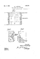
- Figure 5 is a vertical section of a crucible tween rollers to an extent that the openingfiurnace illustrating features of my invenspecific constructions to be given can be fully understood only when knowledge is had of certain general principles of ironless inductive heating discovered by me, I shall first explain these principles in broad outline.
- M is a solid cylindrical mass to be heated by electrical currents induced in it.
- J is an inductor. It consists of a singlelayer coil (of edgewise wound, hollow, fiattened copper tubing) through which both water and electric current flow. J may have any number of turns n which can be wound in a single layer in a length of space H. Heat insulation h is packed between J and M.
- An alternating E. M. F. E is applied to the terminals t t, of coil J.
- An alternating magnetic flux or field is set up on the inside of the coil J. Most of this magnetic flux passes (approximately in the direction of the length of the coil) through the mass M but some of the flux passes through the insulation it between coil J and cylindrical mass M. Only that portion of the total magnetic flux which passes through the mass M can induce electric cur rents in the mass.
- the mass M has the low resistivity of an alloy like brass and if its diameter isseveral inches, the electromagnetic energy will all become converted into heat before the axis is reached ven though the fre-' quency of the current is much reduced; say: to 500 or even less cycles per second. But in this case, we must greatly increase the am-. pere turns of the inductor to secure with reduced frequency the same heating effect as we may obtain with a higher frequency and fewer ampere turns.” If, however, we employ va large current through the coil to secure the needed large number of ampere turns the conductor must have an increased cross section to carry this largeturrent with the same power waste in the coil, as a smaller current athigher frequency produces. For this reason the width of'the conductor is made great and the conductor is then edgewlsc' wound to secure the necessary number of turns and total weight of copper in the cdil.
- Figures 2 is shown a cross section of a mass of greatlength Z and large thickness t.
- a-a is the free surface of this mass assumed to have great extent in the direction vertical to the plane of the paper.
- To the right of the surface 'aa' is an alternating magnetic field having the direction shown by the line p.
- the lines of force of this laternating fieldneach into the mass M asindicated by thedotted lines 9, the field growing less and move into the mass toelectric currents are induced in the mass.
- the direction of flow of these currents in the mass is at right angles to the plane of the paper.
- the amperes per square cm. or the current density are greatest at the surface a-a of the mass and as we move into the mass this current density grows less and lessby a definite law.
- the line 0 given in Figure 3 shows the decrease in the current density as we move into the mass toward' the left from surface aa of Figure 2.
- Steinmetz has shown (p. 383 Theory and Calculation'of Transient Electric Phenom ena and Oscillations) that we may quantitatively express the depth of' penetration for non-magnetic material by the expression where p is the resistivity of the material and N is the frequency of the alternating inducing field.
- the mass may have a greater diameter than this, but for complete converslon of electromagnetic energy into heat energy should not have a much less diameter.
- the inductor coil will in general be made by winding the conductor in a coil having a single layer.
- the advantage obtained by using asingle layer instead of a multiple layer winding has been pointed out by me in my various theoretical treatments of inductive heating.
- edgewise winding of flat conductor is used. This flat conductor is hollow so water may be passed through it to ;l eep it cool and its resistance low.
- One half the atrial section of the inductor when so wound will occupy a certain area, the length of which is H ( Figure l.) and the width of which is t ( Figure 1).
- the width of the inductor is to a certain extent arbitrary for a furnace of a given size, but to give a satisfactory electrical efficiency We have chosen this width such that the coil resistance is low enough to give not over 10% .to 20% loss in the coil of the total power supplied to the furnace. To accomplish this result with a particular furnace wehave found that the width t of the edgewise wound conductor should be approximately one-twentieth of the inside diameter of the coil. Having made this selection for a particular furnacewe have found width of conductor diameter of coil should be approximately maintained for a furnace of an size.
- My invention contemplates the correction of the low power factor of the furnace by means of static condensers used in series with of-phase com onent of the kv-a. or
- the generator needs to have only sulficient kv-a. capacity to carry the power component of the load.
- the total cost of the equipment for supplying power W to the load is the sum of the generator cost and the condenser cost.
- a is the coil
- 5 the crucible
- c asbestos-magnesia heat insulation
- d is a cylinder of micanite about 1/16 inch thick which lines the inside of the coil. The purpose of this is to electrically insulate the coil from the hot crucible.
- Figure 5 does not show the furnace housing nor the mechanism for lifting and pouring the furnace.
- ater inlets and outlets are shown diagrammatically. There are five inlets i i i i i and four outlets 0,, 0
- Equation 19 the dimen sions of the coil, as given in Figure 5, and
- the resistance of the coil is the resistance of the coil.
- the resistance of one turn of solid copper which fills the space 2.8 cm. wide by 33 cm. long is The double wall thickness of the flattened copper tube is 0.234 cm. There are 50 turns, hence space used by copper is 0.234 X 50 11.7 cms.
- the particular alternator used to furnish current for this furnace is rated at 100 kv-a.
- Vve have provided for the circulation of water in the coil and used multiple inlets and outlets.
- the novelty which consists in proportioning the ampere turns in the coil to diameter ofthe charge, the diameter of the coil and the resistivity of the charge substantially the same in furnaces of di erent size.
- former iron the novelty which consists in varying the diameter of the melt directly as the square root of the resistivity of the melt.
- the novelty which consists in maintaining the same percentage of power loss 'in the coil with different sizes of furnace and regardless of the frequency by maintaining the ratio between the square of the number of turns and the linear dimensions of the inductor coil.
- the novelty which consists in selectin the total number of turns in the inductor in direct proportion to the applied voltage selected.
- the novelty which consists in proportioning the furnace dimensions and frequency for resistivity of given charge such that the electrical efliciency of the furnaces of different size shall be substantially independent of the sizes of the furnaces.
- An ironless induction furnace consisting of a solenoidal coil having a single layer and surrounding an approximate cylinder of conducting material to be heated in which the ratio of diameter of conducting material to inside diameter of coil is maintained between the limits of nine to ten and five to ten, and in which the depth of insulation between the inductor coil and the work or crucible is limited substantially to the depth of heat insulation required, combined with static condensers to correct the power factor at generator terminals to substantially unity;
- condensers connected in parallel to the inductor for the purpose and chosen of suflicient capacity to bring the power factor of the combination near unity at source of current supply.
Description
Dec 11, 1928. 1,694,792
E. F. NORTHRUP HIGH FREQUENCY INDUCTION FURNACE Original Filed Nov. 29, 1924 2 Sheets-Sheet 1 Dec. 11, 1926. 1,694,792
' E. F. NORTHRUP .HIGH FREQUENCY INDUCTION FURNACE Original Filed Nov. 29, 1924 2 Sheets-Sheet 2 t FURNACE Patented-Dee. '11, 1928.
UNITED srATEs.
PATENT OFFICE.
' EDWIN I. NORTHBUP, OF PRINCETON, NEW ERSEY, ASSIGNOR TO AJAX ELECTRO- THERMIC CORPORATION,
JERSEY, A CORPORATION OF NEW Immruamoun1v nr mnucrron runnacu.
Application filed November as, 1e24, Serial No 752,885. Renewed July as, 1928.
" My invention relates to inductive heating free from the need for transformer iron and at substantially unity power factor at source of current supply. It has specific reference to certain relations, I have discovered, being chosen between such quantities as; diameter of the charge heated, resistivity of this charge and the internal'and external diam- .eters of the inductor. 10 A further purpose,.for reasons of securing economy 1n equipment costs, is to make practical use of certain brpad relations,
which I have established by theory and Veri-' fled by actual practice between certain es- ,sentialdesi'gn elements entering into a furnace, by employment ofwhich substantialty the same electrical efficiencies may be secured with furnaces widely differing in size. A further purpose is to maintain the ratio of the resistance of the inductor to its inductance low by use of an edgcwise wound coil having a conductorof width definitely related to the diameter of the coil, and,by so doin secure small power losses in the coil itself throughout a considerable range of frequencies. A further purpose is to make use of the relation-which I have discovered between the electrical efliciency of a furnace and the- .30 width .of the conductor when edgewise wound in a single layer primary and the inside diameter of the winding, this width of the conductor, edgewise wound, and the COll '5 diameter being definitely related.
A. further purpose isto employ certain relations in actual constructions between diameter of charge, diameter of coil, resistivity of charge and ampere turns in 0011 to secure absorption of power in charge at highest 4 efficiency.
A further purpose is to employ for the construction of the single-layer indictor coil an edgewise wound conductor meeting the l following specifications and for the followmg purposes; av copper tube is flattened bemately equal to the wall thickness of the tube. continuous length of such tube is edgewise wound to form a single-layer helical coil or solenoid, the separation between the turns bei ng 'ust suflicient to give electrical insulation when filled in with an insulating cement. The width of this copper tubing when flattened is made approximately one twentieth of-the inside diameter of the coil when wound,.the width of the flattened copper tubing thus being chosen as a definite function of the coil diameter. The coil of flattened copper tubing is provided with one or more water inlets and an equal number plus or minus one of water'outletsfor the purpose of passing water through the coil, the flow of water under low pressure being kept suflieient by the provision made of multiple inlets and outlets. The purposes of the construction described are: (1) to keep the resistance of coils of large diameter low by using flattened tubing of an appropriate width and (2) to keep the inductor cool and thereby its resistance down by means of a cooling, fluid which is made to flow through it. Y
Further purposes will appear in the speoi-- ficati'on and in the claims.
I have preferred to illustrate my invention diagrammatically, notattempting to show actual structure even where crucibles are illustrated.
Figure l is a diagrammatic'view to aid illustrating the principles involved in ironless inductive heating. I
Figure 2 is a diagrammatic view showing the distribution and intensity of magnetic field induced in a conducting mass. 0
Figure 3 is a diagrammatic view showing current densities beneath the surface of a conductor.
- Figure 4 is a diagrammatic view intended to illustrate the conditions present for unity 9o power factor.
Figure 5 is a vertical section of a crucible tween rollers to an extent that the openingfiurnace illustrating features of my invenspecific constructions to be given can be fully understood only when knowledge is had of certain general principles of ironless inductive heating discovered by me, I shall first explain these principles in broad outline.
General description of phenomena of iron- Zess inductive heating.
A typical construction for ironless inductive heating is shown diagrammatically in Figure 1. M is a solid cylindrical mass to be heated by electrical currents induced in it. J is an inductor. It consists of a singlelayer coil (of edgewise wound, hollow, fiattened copper tubing) through which both water and electric current flow. J may have any number of turns n which can be wound in a single layer in a length of space H. Heat insulation h is packed between J and M.
An alternating E. M. F. E is applied to the terminals t t, of coil J. An alternating magnetic flux or field is set up on the inside of the coil J. Most of this magnetic flux passes (approximately in the direction of the length of the coil) through the mass M but some of the flux passes through the insulation it between coil J and cylindrical mass M. Only that portion of the total magnetic flux which passes through the mass M can induce electric cur rents in the mass.
If the magnetic field were perfectly uniform over the cross section of the coil taken at right angles to its axis, then the proportion of the total flux to pass through the mass M would be is the area of the cross section of the mass and S is the area of-the cross section of the inside of the coil. The magnetic field, however, fans out near the ends of the coil and the proportion of flux which threads the mass is of the whole'fiux, where small 8 8 I somewhat less than For a COll whose length about equals its diameter and for proport1ons similar to those shown in Figure 1 we can write C =%0.8 as approximately representing the fraction of the total flux which threads the mass M. The constant C is called tions shown, g X .8=.62 approximately and the coupling in this case is said to be 62 per cent.
When the alternating. current in the coil J rises from zero to a maximum, the flux through the mass M, which also rises from zero to a maximum, develops large electric currents in the mass. These currents, which in general flow circumferentially round the mass in its interior, develop heat. The current density of these currents is, however, greatest at the surface of the mass and the density less and less as the axis of the mass is approached. If the mass has a good conductivity and if its diameter is sufficient the currents which are set up in the mass by the alternating magnetic'flux completely dle out, or the current density becomes zero before the axis of the mass is reached. In this case all the electromagnetic energy which is associated with the flux which enters the mass, becomes changed over into heat energy in the substance of the mass. In this way a quantity of heat is given to the mass each time the current in J, which gives rise to the flux, makes an alternation.
Hence it is evident that a current of certain magnitude inJ which makes 1200 alternations a second will put in one second ten times as much heat into the mass as would a current of equal value which makes but 120 alternations in a second. In other words, for a fixed number of ampere turns of the coil J, the rate of heating of the mass is proportional to the frequency of the current employed. Herein lies 9 the advantages of high frequency current for rapid heating of a conducting mass-which advantages I have descrlbed in my Patents Nos. 1,286,394-5, dated December 3, 1918; 1,328,336, January 20, 1920 and others.
The tendency for the circumferentially flowing currents set up in the mass M to concentrate toward the circumference of the mass is more pronounced as the frequency of the current is increased and as the electrical conductivity of the material is higher. It is evident, therefore, that if the mass has a small diameter, andif its resistivityis high, currents of very high frequency must be used, if all the electromagnetic energ is to become converted into heat energy be ore the inflowing energy reaches the axis ofthe mass of small diameter. In fact, rapid and effective heating in this manner of, say, a rod of graphite of 1 diameter can only be accomplished by using a current of atleast 5000 to 20,000 cycles. e
If on the other hand the mass M has the low resistivity of an alloy like brass and if its diameter isseveral inches, the electromagnetic energy will all become converted into heat before the axis is reached ven though the fre-' quency of the current is much reduced; say: to 500 or even less cycles per second. But in this case, we must greatly increase the am-. pere turns of the inductor to secure with reduced frequency the same heating effect as we may obtain with a higher frequency and fewer ampere turns." If, however, we employ va large current through the coil to secure the needed large number of ampere turns the conductor must have an increased cross section to carry this largeturrent with the same power waste in the coil, as a smaller current athigher frequency produces. For this reason the width of'the conductor is made great and the conductor is then edgewlsc' wound to secure the necessary number of turns and total weight of copper in the cdil.
a furnace of any size and we describe by defined and determined by Steinmetz.
.. less intense as, we
" ward the left. Since the field is alternating,
way'of illustration a particular furnace designedto melt,600 lbs. an hour of-red brass when operated with about kilowatts.
Principles on which furnace The depth of penetration of current induced in a conducting mass by an alternating magnetic field of frequency N has been See Chapters VI and VII Transient Elsi-trio Phenomena'.)
In Figures 2 is shown a cross section of a mass of greatlength Z and large thickness t. a-a is the free surface of this mass assumed to have great extent in the direction vertical to the plane of the paper. To the right of the surface 'aa'is an alternating magnetic field having the direction shown by the line p. The lines of force of this laternating fieldneach into the mass M asindicated by thedotted lines 9, the field growing less and move into the mass toelectric currents are induced in the mass. The direction of flow of these currents in the mass is at right angles to the plane of the paper. The amperes per square cm. or the current density are greatest at the surface a-a of the mass and as we move into the mass this current density grows less and lessby a definite law. The line 0 given in Figure 3 shows the decrease in the current density as we move into the mass toward' the left from surface aa of Figure 2.
If we draw a vertical line 2-4, Figure 3, such that the area inclosed by the rectangle 01241-'0 is equal to the area. The lines a and 0 given in Figure 3 show the decrease in the mean squares and instantaneous values,
respectively of current density as we move into the mass toward the left from surface aa of Figure 2.
If we draw a vertical line 2-4, Figure 3, such that the area inclosed by the rectangle 0124 0 is equal to'the area (shown shaded) under the curve 0", then the width 1-2 of this rectangle is defined as the depth of penetration of the current into the mass M. Otherwisestated, 1-2 is the effective penetration of the alternating current into the mass which, having the constant density which exists at the surface, would give the same total current as exists in the mass.
, Steinmetz has shown (p. 383 Theory and Calculation'of Transient Electric Phenom ena and Oscillations) that we may quantitatively express the depth of' penetration for non-magnetic material by the expression where p is the resistivity of the material and N is the frequency of the alternating inducing field.
' This formula applies to a mass having a plane surface. If the surface zv-a is concave I the depth of penetration is less and if the surface is convex thedepth .of penetration is somewhat greater. When an inductor which creates the alternating magnetic field surrounds a cylindricalmass of moderate diamoter, then the surface of the mass is convex and for our purpose we may take By referring to curve 0 Figure 3 we note that if we move intothe mass a depth four times the depth of penetration we find' the actual value of the current density has beof what it is at the surface of the mass."
Hence, we may assert that when we have moved four times the (depth of penetration into the mass we find the heating effect of the current in the mass has become negligible and the electromagnetic energy ofthe alternating magnetic field has become practically all converted into heat energy. Hence, it follows that when we are inducing currents this cylinder should be about eight times the depth of penetration for substantially complete conversion of the electromagnetic energy into heat energy. Or we should make or in round figures write Thus if we are heating a cylinder of molten brass, the resistivity of which is and if we use a frequency of 360 cycles, we should make the diameter of this cylinder at least D=5 10* /40 10- =16.7 ems.
or say, 6 3/4". The mass may have a greater diameter than this, but for complete converslon of electromagnetic energy into heat energy should not have a much less diameter.
As another example assume we wish to heat to the best advantage a rod of Acheson graphlte 0.5 cm. in diameter, what frequency should we use? The resistivity of graphite is about 7 X 10' ohm. By Formula (3) I 7 X 10' 4 f Thus or seven million cycles per second.
It thus appears that we may use to advantage such wide range of frequency as seven million cycles to three hundred and sixty cycles or less according to the diameter and resistivity of the material to'be heated.
The inductor coil will in general be made by winding the conductor in a coil having a single layer. The advantage obtained by using asingle layer instead of a multiple layer winding has been pointed out by me in my various theoretical treatments of inductive heating. To secure with a single layer winding a coil of many turns and low resistance, edgewise winding of flat conductor is used. This flat conductor is hollow so water may be passed through it to ;l eep it cool and its resistance low. One half the atrial section of the inductor when so wound will occupy a certain area, the length of which is H (Figure l.) and the width of which is t (Figure 1). A certain proportion of the area If H is not filled with copper, but is necessarily occupied by space for the water flowv and by insulation between inductor turns.- The easiest way to take account of this when making a calculation of the ohmic resistance of the coil is to assume that the resistivity of the copper is increased and that the copper then fills the entire area If H. Thus if one half the area t H is occupied by non- "With the above conducting material we would assume that the IQSIStIVlty of the copper is doubled. Thus taking the resistivity of copper at the work-' ing temperature, as
' and then treat the cross section t H as if entirely occupied by conductor material.
The selection of the width of the inductor is to a certain extent arbitrary for a furnace of a given size, but to give a satisfactory electrical efficiency We have chosen this width such that the coil resistance is low enough to give not over 10% .to 20% loss in the coil of the total power supplied to the furnace. To accomplish this result with a particular furnace wehave found that the width t of the edgewise wound conductor should be approximately one-twentieth of the inside diameter of the coil. Having made this selection for a particular furnacewe have found width of conductor diameter of coil should be approximately maintained for a furnace of an size.
' The ratio, iameter of mass M to inside dithat the same ratio ameter of coil (Figure 1) should be made is required for'the thickness of the crucible wall. Experience shows that this insulation space must be greater for very high temperature melts than for melts-made at medium temperature. It does not in general, however, need to be greater for a furnace of large diameter than for one of small diameter. Consequently in a very large furnace the ratio diameter of melt inside diameter of coil larger than for a. small one, and thus we obtain for a large furnace a better coupling and a consequent betterpower factor. For purposes of calculation, however, we will armay be made bitrarily choose the ratio 2 05 and maintain this ratio for furnaces of widely different sizes. With this ratio the coupling will be about 51%.' The height of the inductor may with advantage be chosen about equal to its inside diameter. This leads to simplicity in making calculations and is usually a good proportlon for operating conditions.
eneral discussion in mind we summarize as ollows theproportions we have found good by theory and verified by practice and on which we seek patent protecturn is tion as being the first to discover the character and value of such proportions.
Coupling factor. We havelpointed out that this factor, C is approximately the ratio, cross section of diameter of melt divided by cross section of coil, times the arbitrary constant 0.8. Or we cal and we have found it practical to make C=O.5 to 0:7.
Resistance of inductor.
4 Assume that the inductor has one turn and fills the space of length H and width t (F igure 1) less the amount of space used for water flow and insulation. If the inductor were copper and filled the whole space the resistance of this one turn (see Figure 1) would be where A is mean diameter of the one turn coil and 'p'=2X 10 Ohm. is the specific resistance of copper at the working temperature. Since, however, a certain proportion of the area, H t, is not occupied by copper, but by water and insulation (between turns when there are several turns) we take the specific resistance to be greater (see page 13). Let
as representing an average case such as 00-.
ours in practice. Then the resistance of one 1' l ft/ (5) As pointed out (page 4) we have found it advantageous to maintain the ratio width of flattened conductor diameter of coil whatever the size of the furnace. We have found one-twentieth a suitable value forthis ratio. If then we write %=k, a constant, where 20 for good practice, we have 1rp'k If -the same space, H t, is filled with n turns, the resistance will be n times as great as if the space were filled with one turn; hence the resistance of a coil ofn turns may be written,
2 Ik g 7) ()r we conclude that it is necessary and good about the same,
practice in order to preserve the same proportionate power loss in the coil of a furnace of 8t11y'SlZe to so wlnd oursmgle layer coil that 1ts resistance is I That is, we should choose the width of the cdgewise wound conductor such that the resistance of the coil will decrease with the linear dimension of the coil.
Self induction of empty inductor.
When the inductor is empty, namely, the mass M not in it' (Figure 1) its self-induction is L HFD--. -(9) where n is the number of turns in the coil and D is the inside diameter. In the'Bulletin of the Bureau of Standards, vol. 8, No. 7, J anuary 1, 1922, pp. 117, 118, 194, is given a simple formula and table for rapidly calculating the self-induction of any s1nglelayer solenoid.
Relation of frequency, diameter and resistivity of any mass to be heated.
)Ve have shown (page 11) that the diameter of the mass to be heated should not be less than where p is the resistivity of the mass ahd N the frequency employed. Thus we should maintain D0c N' (10) By this we see that the diameter of the melt should be varied directly as the square root of the resistivity of the melt and inversely as the square root of the frequency used.
Reactanee of the inductor.
' In other words, we should vary the reactance of our empty coil direct-1y as the resistivity The reactance of the inductor with no mass of our melt and inversely as the diameter or linear dimensions of the melt.
Power absorbed by mass.
If the conversion of electroma netic into heat energy is complete .before the axis of the mass is reached, then the absorbed power P QNW GLNI where N is thefrequency and W equal to l/QOLP is the energy developed every time the current rises to its maximum value I.
If the current be of sine form and i the effective value of the current,
I =2i and P=2OLNi or, since the reactanee w 2flTNL we have the absorption of power by a mass in a coil (Figure 1) may be found to a fair degree of approximation from the expression where C is the coupling, to the reactance of the coil (empty), and i the current carried by the coil.
Relation (13) is only true provided Relation (3) is maintained. Since (Equation 12) the absorbed power is Poc%(in) 14 Power factor.
Since power is the product of volt-ampcres multlplled by a certain factor F, called the power factor, or in symbols P=EF 15 we can always predict the rate of heating performance of any furnace provided we measure or calculate the power factor.
It is valuable therefore to find if possible an expression which will enable us to calculate, if only approximately, the power factor.
It is only possible to derive such an expression '7 when the material to be heated is non-magnetic. It is possible to obtain (as I have done) a very exact expression for the single case in which the secondary consists of a cylindrical shell of non-magnetic material having a very thin wall. However, if the secondary is a cylindrical mass of solid or liquid material which is non-magnetic and if the diameter of the mass is related to the frequency and its resistivity according to Equation 3, then the following expression is quite approximately true; It is 0.45 C F: am Here is the coupling factor. By the above we note that the power factor depends only on the coupling.
1f the coupling is unity, C=1 and F=0.45 which shows that the power factor cannot exceed 45%. For (i=0, F=0. For C=0.6, F=0.226, or 22.6%. This formula (16) obtained by theory has been confirmed by actual tests. In one test 540 cycles were'used, and in another 315. In these tests made May 24, 1924 experiment gave power factors 0.282, 0.305, and 0.315. The power factor calculated by Equation 16 was 0.314. In this case the coupling C=0J76 and the power used was about 25 kw.
Electrical efiicz'enoy.
z= am --(17)- If the furnace is rightly proportioned in the manner described above this electrical efficiency will be approximately the same for furnaces of different sizes. We may show this to be true as follows: By Equation (14),
'Fn a'i n PK T)" 01 'T)-* where a is a constant. By Equation (8) n railor since we assume the height of the coil H to be maintained proportional to its diameter D we can say that where small b is another constant. Putting these values fonP and 11 in Equation (17) we have Since a and b are both constant quantities we conclude that furnaces of different heights and corresponding diameters will have the same electrical efliciency-whicl1 efliciency we can readily arrange to exceed 80%. Power factor correction.
My invention contemplates the correction of the low power factor of the furnace by means of static condensers used in series with of-phase com onent of the kv-a. or
, ried'by a the coil or connected in shunt with the coil, or by using a synchronous converter with over-excited field. This would usually be connected in shunt to the furnace inductor.
I consider, however, that for power factor correction of high frequency f1 rnaces that static condensers constitute the c ieaper and more practical device. The generator which supplies high frequency current. to the furnace will then deliver its current to aloaded furnace (that is, one absorbing its full rated power) substantially in phase with the generator voltage. In other words,'the generator is only called upon to supply the inphase component of the kv-a. taken by the furnace, or the work current. The outcomponent is then supplied by the con densers or by the synchronous converter if this is used.
If I did not employ a phase correcting device, the low power factor at which my furnace operates would necessitate ,the use of a generator having a prohibitively large kv-a. rating, but because I use a phase correcting device the kv-a. rating of my generator'need be little if any greater thanjthe kw. rating of my furnace.
- Since the cost per kv-a. of condensers is much less than the cost per kv-a. of the generator, there is a substantial saving in cost when the reactive component of thQkv-a. is
carried by condensers instead of being carreatly over-size generator. I shall make t is'im ortant economic feature of m invention stlll more clear, by. expressing t 1e matter in the following way ing both resistance.R and reactance X, it
must have a sufficient kv-a. capacity to supply both .the reactive component and the power component of the load.
If, on 'the other hand, the reactive component of the load is wholly carried by -a shunted negative reactance-X the generator needs to have only sulficient kv-a. capacity to carry the power component of the load. In
reactive generator feeds a receiver circuit .hav-
this case the kv-a. ratingand the kw. rating of the generator are the same.
' Assuming the cost .of the generator in this second case proportional to its kv-a. rating it will also be proportional to its power output. Thus, We can write =AW' where A is a constant and W is the power output expressed in kilowatts.
\Vhere, for example, we have a circuit and load asindlcated by diagram, F igure 4, it is easy to show that the kv-a. rating of the condenser C necessary to raise the power factor f taken at the terminals a-b of the load to 100% it given by the expression where IV is the power expressed in "kilowatts delivered to the load, and f the power factor of the load.
The cost of condensers is (in general) proportional to their kv-a. rating: Hence, We
may write'for condenser [cost I as KWJ '1 f f The total cost of the equipment for supplying power W to the load is the sum of the generator cost and the condenser cost.
. In a formula we have To illustrate-.Froni quotations given by a =W(27.87-+W)=36.25'W.
Thus, if 250 kw. are delivered, electrical equipment cost would be $9062.00. We see that if the generator is operated at its full load rating of 250 kv-a. it will deliver 250 kw. because it operatesv at unity power factor and the total equipment cost for 250 kw.
delivered to a furnace will be $9062.00.
In high frequency generation of electrical power the cost per kv-a. for the generator will always be much greater than the cost per kv-a. for the static condensers to give complete power factor correction. It is therefore a great saving of cost to correct the low power factor of a high frequency induction furnace with sta-tic'condensers. In fact, to attempt to supply power to. such furnace at high frequency without correcting the power factor is wholly impracticable from economic considerations.
I am thefirst to point out this important consideration connected with ironless inductive heating, and I consider that the combined use of condensers and high frequency generation of power for ironless inductive heating constitutes an original and an important feature of my system of inductive heating.
Since, however, my present application relates more particularly to the proportioning of furnace elements to secure high etficiency and substantially the same efiiciency and the same power factor regardless of the nature of the conductive material heated and the frequency available I will not dwell at more length upon methods I have employed for phase correction and for securing. unity power factor. I here make reference to my Patent No. 1,286,395 and the description on page 8 of one of my methods of phase correct-ion.
Having now explained the general principles of the furnace design and having pointed out the necessary proportionment of furnace parts and selection of frequency that I have discovered as being necessary and good for efficient furnace operation I shall illustrate these matters by giving in outline the design of an actual furnace which I have had constructed for the melting of metals, chiefly nonferrous, in 600 pound charges.
Ewample showing application of principles.
designed more particularly for melting and pouring brass, bronze, etc. in about (300 pound lots. The furnace will, however, melt ferrous metals. a is the coil, 5 the crucible, c asbestos-magnesia heat insulation, d is a cylinder of micanite about 1/16 inch thick which lines the inside of the coil. The purpose of this is to electrically insulate the coil from the hot crucible.
Figure 5 does not show the furnace housing nor the mechanism for lifting and pouring the furnace. ater inlets and outlets are shown diagrammatically. There are five inlets i i i i i and four outlets 0,, 0
0 0,. The electrical terminals of the coil are indicated at e, and c It was determined by a rough preliminary calculation that, the coil should be wound with 50 turns and that to make a coil of sufficiently low resistance the conductor should consist of flattened copper tubing 13/16" 0.
The inductance of the coil (when empty). is given by the formula L=an Q 10 henry 19) Where a is the inside radius of the' coil, n
the numberof its turns, and Q, is a constant, the value of which constant Q, is given on page 194, Table IV BulIetin of the Bureau of Standards, Vol. 'VIII, No. 1, J anuary l, 1912. Substitute in Equation 19 the dimen sions of the coil, as given in Figure 5, and
calling n=50, the number of turns, and taking form the table Q,=19.5 we find the inductance of the coil is L=L4 I 10' henry (20) The reactance of the coil (when empty) is given by the formula with 5 ft) cycles we place N=540 and we find w=4.88 ohms (22) The current for operating furnace was in this case obtained from a 100 kv-a., 220 volt, 540 cycle generator driven by a steam turbine.
The resistance of the coil.
The resistance of one turn of solid copper which fills the space 2.8 cm. wide by 33 cm. long is The double wall thickness of the flattened copper tube is 0.234 cm. There are 50 turns, hence space used by copper is 0.234 X 50 11.7 cms.
The length of the spacein which the copper is wound is 33 cms. Hence we call I ge J 11.7
or we take =2.82 Now the resistivity of copper at the working temperature of the coil is about amount of this increase a. measurement of the alternating current resistance must be made at the frequency used. In one case we found the D. C. resistance increased three times using a frequency of 540 cycles. On the pres- But there are fifty turns and the resistance is proportional to the square of the number of turns, (Equation 7 hence the resistance of the coil of fifty turns is 2.82 X 2.7 x l0 =16.04 X 10 ohm.
The coupling factor 0. We estimate C =g% 0.8= 0.5 (nearly) (24) The power factor of this" crucible furnace when the crucible (assumed to be of non-conc n ducting material) is filled with metal near to th'elevel of the top of the coil may be found r =0.40 ohm (23) by Formula (16). Thus 0.45 .5 0.225 /.5 +2-2 o.5 /2.oe25o.5 18% (25) The power. 4.88 ohms (Equation 22) but when the The total power "which this furnace will absorb will be P=EiiF (26) Or as we have found F=0.18
P=E i 0.18 watts (27) where E g is the volts at furnace terminals and i the current through the furnace coil.
The particular alternator used to furnish current for this furnace is rated at 100 kv-a.
and supplied a maximum of 460 amperes at 220 volts.
In this case we prefer to correct the power factor by connecting condensers in series with the generator and furnace as shown in Figure 6. With the series connection the same current passes through furnace coil and through the condensers.
The reason for connecting the condensers in series instead of in shunt with the furnace inductor is found in the fact that the voltage of the generator is low, only 220 to 250 volts. By selecting the correct negative reactance w to connect in series with the furnace, we are able to bring the current not only into exact phase with the generator voltage E but we are further able to raise the voltage E; at the terminals of the furnace so that sufiicient current will flow through the furnace coil to cause the furnace to absorb its full rated power. The voltage drop E, over the furnace is ahead of the current in phase, in this case leading the current by 79, 38'. vThe voltage drop over the negative reactance w is 90 in phase behind the current. These two v0ltages can be combined vectorially to give the resultant voltage which the alternator sup-" plies. The furnace coil has when empty the positive reactance m which we found to equal crucible is full of metal the reactance of the furnace as a whole is different and is less than m. If we call X the .reactance of the loaded furnace, then to secure unity power factor at the generator we must make the negative reaetance It can be shown that the equivalent furnace reactanceX may be determined with a fair degree of approximation to be Since we have taken C=0.5 and w=4.88 we find X=4.27 ohms. By placing w =X= l.27 we secure unity power factor at generator terminals when the furnace is loaded and the generatorwill feed into the circuit as if this consisted of pure ohmic resistance. The current which will then flow will be where E is the generator voltage and R is the equivalent resistance of the furnace.
It can also be shown that where small 1" is the ohmic resistance of the coil which in this case we have taken. as 0.04 ohm (Equation 23). Thus R=0.65 ohm "(32) The power supplied by the generator will be supplied now at unity power factor and it will be a n nus If we wish to deliver kw. to the furnace we must write =i /R +X =3501/0.65 +4f= 1511 volts (40 It is the vectorial addition of 1497 and 1511 which gives E=228.
In the furnace design we have given above it should be noted that we have made use of the principles and the proportioning of parts for which we seek patent protection" 1. We have shown that the diameter of our mass heated should be Since for molten brass =4.0 X 10' and since our frequency is 1 =540 we should make the diameter of our mass at least'l cms. and we have made it 46 cms. v
2. We have used an edgewise wound single layer coil, as explained.
3. 'We have made the width of our inductor divided by the inside diameter of our coil which is near to the ratio 1/20 which is explained as being desirable to have.
4. We have used a flattened copper tubing of wall thickness 0.046 and have left an opening in this between side walls of about 0.046. This approximates the proportion stated as being desirable.
5. Vve have provided for the circulation of water in the coil and used multiple inlets and outlets.
6. The electrical efficiency of our fur nace calculates out as follows, Formula and hence is above After the above calculations were made the A. G. resistance of this coil under the conditions used was found to be about three times its D. G.-resistance and the efficiency proved to be slightly less than 90%. By maintaining the furnace as the capacity which must be used. The current which will flow is t R r65 350.7 amps. (38) The voltage F (Figure 6) at the terminals of the condensers is E,: im 350.7 X 4.27 1497 volts (39) The voltage E, at the terminals of the furnace is BNll2 p1/2 '2". We have used condensers in series with so as to maintain the same value for the generator and inductor and which we-v have chosen of. such value as to give complete power factor correction to our furnace when-loaded. )Ve may add here that when the furnace is not loaded there will be a sufficient excess of positive reactance to prevent the rise of current in the circuit to exceed that of the rated capacity of the generator. If our generator has been built to give a higher voltage, say 1200 volts, we could then with advantage have used our condensers joined in parallel to the furnace coil.
Thus by our descriptions and by the example of the design of a particular furnace we have made clear the important features and elements of our invention.
It isevident that the breadth of this invention is such that there can be a considerable variation in the proportions given and in the method of applying the principles set forth and the reatest possible variation in the details of esign without departing from the spirit and intent of this invention.
Having thus described my invention what I claim as new and desire to secure by Letters Patent is 2- 1. In inductive heating free from transformer iron, the novelty which consistsin providing a single layer of inductor of greater -conductor depth than thickness having a depth radially bearing a definite proportion to the'diameter of the charge to make the loss of power in the inductor substantially independent of the size of the inductor.
2. In inductive heating free from transformer iron to secure hi hest efiiciency and power factor and keep own the frequency the novelty. which consistsin proportioning the diameter of the charge to the diameter of the coil and the resistivity of the charge.
3. In inductive heating free from transformer iron to secure hi hest elliciency and power factor and keep down the frequency the novelty which consists in proportioning the ampere turns in the coil to diameter ofthe charge, the diameter of the coil and the resistivity of the charge substantially the same in furnaces of di erent size.
4. In inductive heating free from trans-.
former iron, the novelty which consists in varying the diameter of the melt directly as the square root of the resistivity of the melt.
5- The method of maintaining efficiencies substantiallyconstant for furnaces of different sizes, which consists in maintainin the same relations betwen the heights and diameters of the materials treated and the heights and radial depths of the coil windings.
6. In inductive heating free from transformer iron utilizing a single layer coil of flattened hollow copper tubing, the novelty which consists in maintaining the same percentage of power loss in the coil with different sizes of furnace and regardless of the frequency.
7. In inductive heating free from transformer iron utilizing a single layer coil of flattened hollow copper tubing, the novelty which consists in maintaining the same percentage of power loss 'in the coil with different sizes of furnace and regardless of the frequency by maintaining the ratio between the square of the number of turns and the linear dimensions of the inductor coil.
8. In inductive heating free from transformer iron utilizing a single layer c0il-of flattened hollow copper tubing, the novelty which consists in maintaining the same percentage of powerloss in the coil withdifl'ercut sizes of furnace and regardless of the frequency by choosing the radial de th of the flattened tubing as a proportion o the diameter of the mass. g
9. In inductive heating free from transformer iron, the process of determining the reactance of the inductors for furnaces for different metals and sizes which consists in varying the reactance of the inductor directly as the resistivity of the material and inversely as the lineal dimensions of the melt.
10, In ironless inductive heati by a coil surrounding a continuous cylin rical conducting mass, the novelty which consists in selectin the total number of turns in the inductor in direct proportion to the applied voltage selected.
11. In ironless inductive heating by an inductor surrounding a cylindrical charge, the novelty which consists in proportioning the furnace dimensions and frequency for resistivity of given charge such that the electrical efliciency of the furnaces of different size shall be substantially independent of the sizes of the furnaces.
12. An ironless induction furnace consisting of a solenoidal coil having a single layer and surrounding an approximate cylinder of conducting material to be heated in which the ratio of diameter of conducting material to inside diameter of coil is maintained between the limits of nine to ten and five to ten, and in which the depth of insulation between the inductor coil and the work or crucible is limited substantially to the depth of heat insulation required, combined with static condensers to correct the power factor at generator terminals to substantially unity;
13. The combination of an alternating current, generator, an edgewise wound flattened tube, artificially cooled, wound in a singlelayer coil about the mass to be heated by ironless induction and having radial width of flattened tube chosen to be in the limits one to eight to one to twenty-five of the inside diameter of the inductor, the insulation within the inductor being restricted in depth to substantially the heat insulation needed, and
condensers connected in series with the inducstantially the heat insulation needed, and
condensers connected in parallel to the inductor for the purpose and chosen of suflicient capacity to bring the power factor of the combination near unity at source of current supply.
15. The combination of an alternating current generator, an ironless inductive heater operated with current of higher frequency than normal with condensers connected in series with the generator and heater, the neg ative reactance of which is equal to the equivalent positive reactance of the heater thereby giving a hi her voltage at the heater termi-- nals than t e supply voltage and bringing the power factor at the source of current supply tonear unity. 4
EDWIN F. NORTHRUP.
Priority Applications (1)
| Application Number | Priority Date | Filing Date | Title |
|---|---|---|---|
| US752885A US1694792A (en) | 1924-11-29 | 1924-11-29 | High-frequency induction furnace |
Applications Claiming Priority (1)
| Application Number | Priority Date | Filing Date | Title |
|---|---|---|---|
| US752885A US1694792A (en) | 1924-11-29 | 1924-11-29 | High-frequency induction furnace |
Publications (1)
| Publication Number | Publication Date |
|---|---|
| US1694792A true US1694792A (en) | 1928-12-11 |
Family
ID=25028297
Family Applications (1)
| Application Number | Title | Priority Date | Filing Date |
|---|---|---|---|
| US752885A Expired - Lifetime US1694792A (en) | 1924-11-29 | 1924-11-29 | High-frequency induction furnace |
Country Status (1)
| Country | Link |
|---|---|
| US (1) | US1694792A (en) |
Cited By (3)
| Publication number | Priority date | Publication date | Assignee | Title |
|---|---|---|---|---|
| US2538979A (en) * | 1941-08-19 | 1951-01-23 | Applic Electro Thermiques Soc | Induction furnace |
| US2567525A (en) * | 1945-11-02 | 1951-09-11 | Republic Steel Corp | Apparatus for casting metals |
| US2643201A (en) * | 1949-12-24 | 1953-06-23 | Nat Res Corp | Coating method and apparatus therefor |
-
1924
- 1924-11-29 US US752885A patent/US1694792A/en not_active Expired - Lifetime
Cited By (3)
| Publication number | Priority date | Publication date | Assignee | Title |
|---|---|---|---|---|
| US2538979A (en) * | 1941-08-19 | 1951-01-23 | Applic Electro Thermiques Soc | Induction furnace |
| US2567525A (en) * | 1945-11-02 | 1951-09-11 | Republic Steel Corp | Apparatus for casting metals |
| US2643201A (en) * | 1949-12-24 | 1953-06-23 | Nat Res Corp | Coating method and apparatus therefor |
Similar Documents
| Publication | Publication Date | Title |
|---|---|---|
| US2181274A (en) | Induction heater construction | |
| Semiatin | Elements of induction heating: design, control, and applications | |
| US3396342A (en) | Power supply circuit for continuous wave magnetron operated by pulsed direct current | |
| US5006683A (en) | Device for the electrical induction heating of a fluid contained in a pipeline | |
| US2748240A (en) | Induction heating systems | |
| US2811623A (en) | Method of heating metal billets by low frequency electrical power | |
| US1694792A (en) | High-frequency induction furnace | |
| US2151035A (en) | Transformer | |
| US2770196A (en) | Electromagnetic interaction pump | |
| US2229680A (en) | Polyphase high frequency heating device | |
| US3632975A (en) | Long heat-generating pipe utilizing skin effect of ac having one or more impedance elements in the circuit | |
| US3210509A (en) | Method of and apparatus for electromagnetically deforming metal | |
| US3040230A (en) | Single phase power supply system having a multiphase source | |
| US2408190A (en) | Magnetic induction heating of thinwalled nonmagnetic metallic tubes | |
| US1904665A (en) | Magnetic return circuit | |
| US1795926A (en) | Induction furnace | |
| Baker | Heating of nonmagnetic electric conductors by magnetic induction—Longitudinal flux | |
| US1983544A (en) | Arrangement for supply of current to electrothermic melting furnaces | |
| US3280350A (en) | Magnetohydrodynamic generator | |
| US1823908A (en) | Induction furnace | |
| US2676232A (en) | Arrangement for thoroughly heating of large billets | |
| US2579522A (en) | Transformer construction | |
| US1694791A (en) | Induction electric furnace | |
| RU193008U1 (en) | Three section inductor | |
| US2948797A (en) | Annealing furnace |