US1694335A - Means for automatically discharging liquids from chambers, automatic fountains, and the like devices - Google Patents
Means for automatically discharging liquids from chambers, automatic fountains, and the like devices Download PDFInfo
- Publication number
- US1694335A US1694335A US241335A US24133527A US1694335A US 1694335 A US1694335 A US 1694335A US 241335 A US241335 A US 241335A US 24133527 A US24133527 A US 24133527A US 1694335 A US1694335 A US 1694335A
- Authority
- US
- United States
- Prior art keywords
- chamber
- liquid
- pipe
- pressure
- gas pressure
- Prior art date
- Legal status (The legal status is an assumption and is not a legal conclusion. Google has not performed a legal analysis and makes no representation as to the accuracy of the status listed.)
- Expired - Lifetime
Links
- 239000007788 liquid Substances 0.000 title description 58
- 238000007599 discharging Methods 0.000 title description 5
- 239000007789 gas Substances 0.000 description 33
- 239000003792 electrolyte Substances 0.000 description 17
- XLYOFNOQVPJJNP-UHFFFAOYSA-N water Substances O XLYOFNOQVPJJNP-UHFFFAOYSA-N 0.000 description 7
- QSHDDOUJBYECFT-UHFFFAOYSA-N mercury Chemical compound [Hg] QSHDDOUJBYECFT-UHFFFAOYSA-N 0.000 description 6
- 229910052753 mercury Inorganic materials 0.000 description 6
- 230000004048 modification Effects 0.000 description 6
- 238000012986 modification Methods 0.000 description 6
- 239000012530 fluid Substances 0.000 description 5
- 239000000126 substance Substances 0.000 description 5
- 238000013022 venting Methods 0.000 description 4
- 238000010276 construction Methods 0.000 description 3
- 239000000645 desinfectant Substances 0.000 description 2
- BASFCYQUMIYNBI-UHFFFAOYSA-N platinum Chemical compound [Pt] BASFCYQUMIYNBI-UHFFFAOYSA-N 0.000 description 2
- BVKZGUZCCUSVTD-UHFFFAOYSA-L Carbonate Chemical compound [O-]C([O-])=O BVKZGUZCCUSVTD-UHFFFAOYSA-L 0.000 description 1
- 241000238366 Cephalopoda Species 0.000 description 1
- CBENFWSGALASAD-UHFFFAOYSA-N Ozone Chemical compound [O-][O+]=O CBENFWSGALASAD-UHFFFAOYSA-N 0.000 description 1
- CDBYLPFSWZWCQE-UHFFFAOYSA-L Sodium Carbonate Chemical compound [Na+].[Na+].[O-]C([O-])=O CDBYLPFSWZWCQE-UHFFFAOYSA-L 0.000 description 1
- FEWJPZIEWOKRBE-UHFFFAOYSA-N Tartaric acid Natural products [H+].[H+].[O-]C(=O)C(O)C(O)C([O-])=O FEWJPZIEWOKRBE-UHFFFAOYSA-N 0.000 description 1
- 238000004887 air purification Methods 0.000 description 1
- QVGXLLKOCUKJST-UHFFFAOYSA-N atomic oxygen Chemical compound [O] QVGXLLKOCUKJST-UHFFFAOYSA-N 0.000 description 1
- 239000000084 colloidal system Substances 0.000 description 1
- 238000004040 coloring Methods 0.000 description 1
- 238000010494 dissociation reaction Methods 0.000 description 1
- 230000005593 dissociations Effects 0.000 description 1
- 238000005868 electrolysis reaction Methods 0.000 description 1
- 239000013505 freshwater Substances 0.000 description 1
- 239000011521 glass Substances 0.000 description 1
- 238000010438 heat treatment Methods 0.000 description 1
- 239000011810 insulating material Substances 0.000 description 1
- 238000009413 insulation Methods 0.000 description 1
- 239000001301 oxygen Substances 0.000 description 1
- 229910052760 oxygen Inorganic materials 0.000 description 1
- 238000005192 partition Methods 0.000 description 1
- 229910052697 platinum Inorganic materials 0.000 description 1
- 238000009877 rendering Methods 0.000 description 1
- 230000000630 rising effect Effects 0.000 description 1
- 238000007789 sealing Methods 0.000 description 1
- 238000005507 spraying Methods 0.000 description 1
- 239000008399 tap water Substances 0.000 description 1
- 235000020679 tap water Nutrition 0.000 description 1
- 235000002906 tartaric acid Nutrition 0.000 description 1
- 239000011975 tartaric acid Substances 0.000 description 1
- 108010063955 thrombin receptor peptide (42-47) Proteins 0.000 description 1
Images


Classifications
-
- B—PERFORMING OPERATIONS; TRANSPORTING
- B05—SPRAYING OR ATOMISING IN GENERAL; APPLYING FLUENT MATERIALS TO SURFACES, IN GENERAL
- B05B—SPRAYING APPARATUS; ATOMISING APPARATUS; NOZZLES
- B05B17/00—Apparatus for spraying or atomising liquids or other fluent materials, not covered by the preceding groups
- B05B17/08—Fountains
Definitions
- This invention relates to means for automatically discl-zarging liquids from chambers, automatic fountains and the like devices, and has for one of its principal objects to provide an apparatus in which ie necessity for mechanically moving parts is obviated.
- the invention while not limited in its application thereto, is particularly suitable for automatic fountains, humiditying devices, air purifying devices and the like apparatus, in which a chamber containing liquid is re quired to be discharged.
- the invention envisages the provision or" means for automatically charging and discharging a chamber, substantially without the use of mechanically moving parts and to this end he said means comprise in combination a chamber adapted to contain iquid, means for applying gas pressure to said liquid, means for permitting egress of said liquid under the application of said gas pressure, liquid inlet means, and means, which may be intermittent in action, for preventinc the application of said gas pressure to said inletmeans, so that the said chamber may receive liquid through said liquid inlet means.
- the means for preventing the application of said gas pressure to said liquid inlet means may comprise means for releasing said re when the chamber has been disto a predetermined extent.
- m ns for applying gas pressure to the liquid within the chamber may comprise an 35 electrolyte, and electrodes immersed therein, whereby said electrolyte may be electrolytically dissociated to generate gas;
- the said me s may comprise a cylinder of gas under re, a cylinder of chemicals adapted to iv to form under pressure or a n :y be used to apply pressure alone to .2. squid and for instance by heating cl'iamber containing the liquid.
- the chamber may itself the ele trolyte the s id chairted to accumulate or ma 2: said electrolyte.
- an automatic fountain suitable for decorative and/orair humidifying or purifying purposes oomprises a vertical cylindrical container adapted to be partly filled with an electrolyte, such as impure water (ordinary tap water)v and provided at or near its base with two fiat platinum or like electrodes. Attached to the top of the container and concentric therewith, is a fiat circular basin'which communicates with the said container through a. valve or valves adapted automatically to be opened, when the level of the electrolyte falls below a predetermined amount, and to be closed when the container has been refilld to apredetermined extent.
- an electrolyte such as impure water (ordinary tap water)v
- an electrolyte such as impure water (ordinary tap water)v
- two fiat platinum or like electrodes Attached to the top of the container and concentric therewith, is a fiat circular basin'which communicates with the said container through a.
- valve or valves adapted automatically to be opened, when the level of the electrolyte falls below a predetermined
- atube open at its lower end and passing through the dividing wall between tile container, giving rise to gas pressure which forces the electrolyte up the tube and through the nozzle or spraying device, when it is caught by the basin.
- the level of the electrolyte in the container tells a predeterminedamount, a vent opened, the gases otdissociation are re-. is "d, the container is refilled to a predetermined level from the basin, the vent closes andtlie cycle of operations recolmnences,
- the products of electrolysis will contain oxygen, a gaswhich possesses valuable air purification properties.
- any known means such as brush discharge may be provided to generate ozone in the gases of dissociation.
- the as, aressure electrolyte such, for example, as a scent or disinfectant.
- the second fluid may be separated from the electrolyte by means of a wall or partition, the arrange ment being such that the gas pressure operates upon the surface of the second fluid, into which the output tube dips.
- the'valves employed for the return of fluid from the basin (where such return is desired) lead into that part of the container wherein is the second fluid.
- an electric lamp may be provided in or upon the said fountain, and in some cases may conveniently be connected in series with the electrodes.
- a scent or a disinfectant or colouring matter such as fiuorescein or a colloid, may be mixed with the electrolyte.
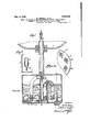
- Figure 1 is a vertical sectional view throughone form of the invent-ion
- Figure 1 is a detail horizontal sectional view of a modification applicable to said form
- Figure 2 is a detail vertical section of a non-return valve which may be substituted for the mercury trap or valve of Figure 1;
- Figure 8 is a vertical sectional view taken through a form of the invention in which a chemical is used to generate gas
- Figure 4 is a view partly in elevation and partly in vertical section showing the invention built into an ornamental fountain and table lamp.
- 1 is an ornamental basin beneath which is situated a chamber 2.
- This pipe forms the liquid egress means, the jet rendering it resistant to liquid flow.
- the liquid inlet means comprise a second pipe 5, concentric with and surrounding the pipe 3, leading from the basin 1 to the chamber 2 and terminating in a pipe 9 which dips into a mercury trap 6, the mercury of which is indicated at 7 thus forming a valve at the inlet of said pipe
- avertical tube 8 open at the top, extending from the bottom of the chamber almost to the top, the inlet pipe communicating with the chamber on the outside of the vertical tube.
- a siphon tube 10 communicates between the eXterior of the vertical tube 8 and Situated within the chamber then filling the vertical tube to a like level.
- the water is dissociated by the electrodes, and. ages pressure is there by generated which forces the water up the outlet pipe through the et at the top thereof, whence it falls into the basin.
- the gas pressure closes the mercury trap by creating a hydraulic head of mercury in the pipe 9.
- each pair of electrodes is situated in a vertical tubular container 11 of glass or other insulating material, open at the top, said containers being arranged around and within the chamber. In this way effective insulation is obtained between the pairs of electrodes.
- the mercury trap is replaced by a rubber nonreturn valve 13' ( Figure 2), fitted over the end of the pipe 9.
- the electrodes are replaced by a cylinder 14 of chemicals, adapted to generate gas.
- the cylinder may be centrally situated andthe inlet and outlet pipes, siphon, etc, arranged in an annulus about the said cylinder, which may thus be made readily removable through the base, top or side of the chamber.
- FIG. 3 One convenient form of chemically operated automatic fountain is illustrated in Figure 3.
- This arrangement which is intended to be immersed in a container or bath of water (not shown), comprises an annular case 14 situated in the upper part of a casing 2 and containing any convenient known chemij cals, adapted. to generate gas which isfree to exert pressure upon a liquid in the lower part of the casing 2.
- the gas paths are not shown in the figure.
- 20 is a safety pressure valve similar to the well known bicycle tire valve and comprising a rubber sleeveembraeing and normally sealing a pierced tube.
- the chemicals may include dilute tartaric acid and a tablet 15 of fused anhydrous carbonate of soda, adapted to be dissociated thereby, the said tablet being cylindrical in form and waxed all over, except upon one flatface 16, so that chemical action will proceed at a substantially constantrate.
- the liquid inlet means con prise a pipe 9 and nonreturn valve 13, situated at the bottom of the casing; for the rest, the device is deemed self-explanatory from the figure.
- FIG. 4 which shows an ornamental automaticiountain made in the form of a table lamp, intermittent action of the fountain is avoided and a continuous jet of water obtained.
- the apparatus designated generally by the letter F, is a chamber charging and discharging device, according to any of the hercinbeiore described constructions.
- the outlet pipe 3, however, of the device is extended upwards and terminates in a circular header tank 21, open to atmosphere at 22 and provided with an overflow pipe 23.
- a return pipe 24 leads has-i: "from the header tank and terminates in a jet 25 located centrally in a basin 1.
- 26 are electrical lamps which, together with an ornamental shade 27, are carried by the tank.
- the lamps are energized from wires'led up a tube 28, which, together with the pipes 3, 24, serve to carry the header tank.
- the pipes 8, 2 and 28 are of hexagonal section and are nested together. It will be seen that the action of the tank 21 is to retain a hydraulic head, thus keeping the fountain in continuous operation.
- a chamber adapted to contain a liquid
- means for substantially continuously creating gas pressure in the chamber a pipe leading from the chamber through which the liquid is discharged by saic. gas pressure
- inlet means having a valve means normally held closed by said gas pressure, said pipe serving to vent said gas pressure when the liquid level falls below a predetermined point in said chamber to allow opening of said valve means and inflow of liquid, and means for maintaining said pipe open for venting said gas pressure until the liquid level rises to a predetermined point in said chamber.
- a chamber adapted to contain a liquid
- means for substantially continuously creating pressure in the chamber a pipe loading from the chamber through wl lch the liquid is discharged by said gas pressure
- inlet means having a valve means normally held closed by pressure, said pipe serving to vent said gas pressure when the liquid level falls below a predetermined point in said chamber to allow opening of said valve means and inflow of liquid, and means for isolating the inflowing liquid.
- siphon means for conveying the liquid to said discharge pipe to seal the same and be dis charged therethrough on the liquid reacl'iing a predetermined level.
- a chamber adapted. to contain a liquid, meanstor substantially con tinuously creating ga'spressure in the chamber, a pipe leading from the chamber through which the liquid is discharged by said gas pressure, inlet means having a valve means normally held closed by saic.
- said plpe serving to vent said gas pressure means in said chamber for continuously dissociating said electrolyte to create gas pressure, a pipe leading from said chamber through which said electrolyte is discharged by said gas pressure, electrolyte inlet means having acheclrvalve means held closed by said gas pressure, means for venting said gas pressure when the electrolyte level falls below a predetermined point in said chamber to allow opening of said check valve means and inflow of electrolyte, and means for maintaining said venting means open until the electrolyte level rises to a predetermined point in said chamber.
- a chamber adapted to contain a liquid
- means for substantially continuously creating pressure in the chamber a pipe communicating with the chamber adjacent the lower part thereof and extending upwardly from the chamber through which the pressure discharges the liquid, means to receive the liquid from said pipe, means for conducting the liquid from the receiving means to said chamber, check means acted on by said pressure to prevent flow through said conducting means, said pipe means serving to vent said pressure after the liquid level has fallen to a predetermined point to allow said check means to open for inflow of liquid, and means for maintaining said pipe open for venting said pressure until the liquid level rises to a predetermined point in said chamber.
- a chamber to contain a liquid
- means for substai'itially continuously creating pressure in the chamber means forming a passage for the discharge of the liquid from the chamber under said pressure and means for the return of the liquid to said chamber
- said last named means including a device functioning as a valve normally held against opening by said pressure, and means serving to vent said pressure when the liquid level falls to a predetermined extent and until the liquid level rises to a point.
- a chamber to contain a-Vliquid means for substantially continuously predetermined creating pressure in the chamber, a tube rising from the base of the chamber and open above said base, a pipe disposed with its lower end in the tube and open adjacent the base of the latter for discharge of liquid upwardly therethrough by said pressure, an inlet pipe arranged to receive discharged fluid, the discharge pipe extending for a portion of its length through the inlet pipe, said inlet pipe having an offset portion disposed adjacent the base of and Within said, chamber check means for the lower end of said inlet pipe normallyheld closed by saidpressure,
- said discharge pipe serving to vent pressure whenthe liquid level falls below a predetern'iined point in said chamber to allow opening oi?
- said check means an d. inflow of liquid, and siphon means for conveying the liquid to said discharge pipe to seal the same and be discharged therethrough on the liquid reaching a predetermined level.
Landscapes
- Filling, Topping-Up Batteries (AREA)
Description
Dec. 4, 1928. 1,694,335
G. MURRAY ET AL MEANS FOR AUTOMATICALLY DISCHARGING LIQUIDS FROM CHAMBERS,
AUTOMATIC FOUNTAINS, AND THE LIKE DEVICES Filed Dec. 20, 1927 3 Sheets-Sheet 1 zmmoas:
GEORGE MURRAY VICTOR o. SIMPKINS} By their Attorneys,
Dec. 4,1928.
MEANS FOR AUTOMATI AUTOMATIC F G. MURRAY ET AL CALL! DISCHARGING LIQUIDS FROM CHAMBERS,
OUNTAINS', AND THE LIKE DEVICES Filed Dec. 20, 1927 3 Sheets-Sheet, 2
GEORGE man, VICTOR o. smrnns,
a By theliwtarneys Dec. 4, 1928. 1,694,335
G. MURRAY ET AL MEANS FOR AUTOMATICALLY DISGHARGING LIQUIDS FROM CHAMBERS,
7 AUTOMATIC FOUNTAINS, AND THE LIKE nnvrcns Filed Dec. 20, 192'!- 5 Sheets-Sheet 'INVENTORS GEORGE MURRAY VICTOR o. smxms,
By their Attorneys,
head-35 l l'l? ltd;
IVIURB-AY AND "-TICTQR OYVEN SIIVIPKIHS, OF LOI'i'DQN, ENGLAND.
I IEAIQ'S AUTOTEATIGALLY DISCEIAEGIHG LIQUIDS FRQIE CHAMBERS, AUTOMATIC EI'QUNTAINES, AND THE LIKE DEVICES, I r i l I Anplization filed Decem er 20, 192?, Serial No. 241,335, and in Britain December 18, 1926.
This invention relates to means for automatically discl-zarging liquids from chambers, automatic fountains and the like devices, and has for one of its principal objects to provide an apparatus in which ie necessity for mechanically moving parts is obviated.
The invention, while not limited in its application thereto, is particularly suitable for automatic fountains, humiditying devices, air purifying devices and the like apparatus, in which a chamber containing liquid is re quired to be discharged.
The invention envisages the provision or" means for automatically charging and discharging a chamber, substantially without the use of mechanically moving parts and to this end he said means comprise in combination a chamber adapted to contain iquid, means for applying gas pressure to said liquid, means for permitting egress of said liquid under the application of said gas pressure, liquid inlet means, and means, which may be intermittent in action, for preventinc the application of said gas pressure to said inletmeans, so that the said chamber may receive liquid through said liquid inlet means. i
The means for preventing the application of said gas pressure to said liquid inlet means may comprise means for releasing said re when the chamber has been disto a predetermined extent. m ns for applying gas pressure to the liquid within the chamber may comprise an 35 electrolyte, and electrodes immersed therein, whereby said electrolyte may be electrolytically dissociated to generate gas; the said me s may comprise a cylinder of gas under re, a cylinder of chemicals adapted to iv to form under pressure or a n :y be used to apply pressure alone to .2. squid and for instance by heating cl'iamber containing the liquid.
- liquid u bin the chamber may itself the ele trolyte the s id chairted to accumulate or ma 2: said electrolyte.
accordance with this invention, mg and discha ging a me in combination a Means, "for automatically cha chamber, comp s said liquid under; ie pressure and adapted s pressure vhen the chambor atain gas o contain liquid, means for to said liouid, means has been discharged to a predetermined ext and liquid inlet means to saidchamber, the said last mentionedmeans incoporating means for retaining a hydraulic head balancing the resistance of the liquid egress means, whereby the chamber is prevented; from recharging until the gas pressure is re leased. V
In one form of construction an automatic fountain suitable for decorative and/orair humidifying or purifying purposes, oomprises a vertical cylindrical container adapted to be partly filled with an electrolyte, such as impure water (ordinary tap water)v and provided at or near its base with two fiat platinum or like electrodes. Attached to the top of the container and concentric therewith, is a fiat circular basin'which communicates with the said container through a. valve or valves adapted automatically to be opened, when the level of the electrolyte falls below a predetermined amount, and to be closed when the container has been refilld to apredetermined extent. Located within the container is atube open at its lower end and passing through the dividing wall between tile container, giving rise to gas pressure which forces the electrolyte up the tube and through the nozzle or spraying device, when it is caught by the basin. After a period Of, time, the level of the electrolyte in the container tells a predeterminedamount, a vent opened, the gases otdissociation are re-. is "d, the container is refilled to a predetermined level from the basin, the vent closes andtlie cycle of operations recolmnences,
It will be appreciated that when water is employed as the electrolyte, the products of electrolysis will contain oxygen, a gaswhich possesses valuable air purification properties. lt desired, any known means (such as brush discharge) may be provided to generate ozone in the gases of dissociation.
In a further modification the as, aressure electrolyte, such, for example, as a scent or disinfectant. For this purpose the second fluid may be separated from the electrolyte by means of a wall or partition, the arrange ment being such that the gas pressure operates upon the surface of the second fluid, into which the output tube dips. In such an arrangement the'valves employed for the return of fluid from the basin (where such return is desired) lead into that part of the container wherein is the second fluid.
If desired, when the invention is applied to fountains for decorative purposes, an electric lamp may be provided in or upon the said fountain, and in some cases may conveniently be connected in series with the electrodes.
Again, if desired, a scent or a disinfectant or colouring matter, such as fiuorescein or a colloid, may be mixed with the electrolyte.
The invention is illustrated in the accompanying drawings, in which are shown QX- amples of constructions of automatic fountains in accordance with the said invention.
' In said drawings:
Figure 1 is a vertical sectional view throughone form of the invent-ion;
Figure 1 is a detail horizontal sectional view of a modification applicable to said form;
Figure 2 is a detail vertical section of a non-return valve which may be substituted for the mercury trap or valve of Figure 1;
Figure 8 is a vertical sectional view taken through a form of the invention in which a chemical is used to generate gas;
Figure 4: is a view partly in elevation and partly in vertical section showing the invention built into an ornamental fountain and table lamp.
Referring first to Figure 1, 1 is an ornamental basin beneath which is situated a chamber 2. A pipe 3, terminating at its upper end in a jet 4, projects downwards into the chamber almost to the bottom thereof. This pipe forms the liquid egress means, the jet rendering it resistant to liquid flow. The liquid inlet means comprise a second pipe 5, concentric with and surrounding the pipe 3, leading from the basin 1 to the chamber 2 and terminating in a pipe 9 which dips into a mercury trap 6, the mercury of which is indicated at 7 thus forming a valve at the inlet of said pipe Surrounding the pipe 3 is avertical tube 8, open at the top, extending from the bottom of the chamber almost to the top, the inlet pipe communicating with the chamber on the outside of the vertical tube. A siphon tube 10 communicates between the eXterior of the vertical tube 8 and Situated within the chamber then filling the vertical tube to a like level.
If the current be on, the water is dissociated by the electrodes, and. ages pressure is there by generated which forces the water up the outlet pipe through the et at the top thereof, whence it falls into the basin. At the same time the gas pressure closes the mercury trap by creating a hydraulic head of mercury in the pipe 9. As water is discharged through the outlet pipe itis replaced by fresh water through the siphon tube 10, and the action proceeds until the level of liquid falls to such an extent that the gas is released from the chamber through the pipe 3. This removes the pressure maintaining the hydraulic head in the pipe 9, and the chamber therefor refills from the basin, the gas displaced by r the incoming liquid escaping through the pipe 8.
In a modification as shown fragmentarily in plan in Figure 1, each pair of electrodes is situated in a vertical tubular container 11 of glass or other insulating material, open at the top, said containers being arranged around and within the chamber. In this way effective insulation is obtained between the pairs of electrodes.
In a further modification the mercury trap is replaced by a rubber nonreturn valve 13' (Figure 2), fitted over the end of the pipe 9. In a further modification the electrodes are replaced by a cylinder 14 of chemicals, adapted to generate gas. In such an arrangement the cylinder may be centrally situated andthe inlet and outlet pipes, siphon, etc, arranged in an annulus about the said cylinder, which may thus be made readily removable through the base, top or side of the chamber.
One convenient form of chemically operated automatic fountain is illustrated in Figure 3. This arrangement, which is intended to be immersed in a container or bath of water (not shown), comprises an annular case 14 situated in the upper part of a casing 2 and containing any convenient known chemij cals, adapted. to generate gas which isfree to exert pressure upon a liquid in the lower part of the casing 2. (The gas paths are not shown in the figure.) 20 is a safety pressure valve similar to the well known bicycle tire valve and comprising a rubber sleeveembraeing and normally sealing a pierced tube. The chemicals may include dilute tartaric acid and a tablet 15 of fused anhydrous carbonate of soda, adapted to be dissociated thereby, the said tablet being cylindrical in form and waxed all over, except upon one flatface 16, so that chemical action will proceed at a substantially constantrate. As will be seen, the liquid inlet means con prise a pipe 9 and nonreturn valve 13, situated at the bottom of the casing; for the rest, the device is deemed self-explanatory from the figure.
In the modification illustrated in Figure 4, which shows an ornamental automaticiountain made in the form of a table lamp, intermittent action of the fountain is avoided and a continuous jet of water obtained. In this figure the apparatus, designated generally by the letter F, is a chamber charging and discharging device, according to any of the hercinbeiore described constructions. The outlet pipe 3, however, of the device is extended upwards and terminates in a circular header tank 21, open to atmosphere at 22 and provided with an overflow pipe 23. A return pipe 24 leads has-i: "from the header tank and terminates in a jet 25 located centrally in a basin 1. 26 are electrical lamps which, together with an ornamental shade 27, are carried by the tank. The lamps are energized from wires'led up a tube 28, which, together with the pipes 3, 24, serve to carry the header tank. The pipes 8, 2 and 28 are of hexagonal section and are nested together. It will be seen that the action of the tank 21 is to retain a hydraulic head, thus keeping the fountain in continuous operation.
We claim 1. In combination, a chamber adapted to contain a liquid, means for substantially continuously creating gas pressure in the chamber, a pipe leading from the chamber through which the liquid is discharged by saic. gas pressure, inlet means having a valve means normally held closed by said gas pressure, said pipe serving to vent said gas pressure when the liquid level falls below a predetermined point in said chamber to allow opening of said valve means and inflow of liquid, and means for maintaining said pipe open for venting said gas pressure until the liquid level rises to a predetermined point in said chamber. v
In combination, a chamber adapted to contain a liquid, means for substantially continuously creating pressure in the chamber, a pipe loading from the chamber through wl lch the liquid is discharged by said gas pressure, inlet means having a valve means normally held closed by pressure, said pipe serving to vent said gas pressure when the liquid level falls below a predetermined point in said chamber to allow opening of said valve means and inflow of liquid, and means for isolating the inflowing liquid. from the discharge pipe, and siphon means for conveying the liquid to said discharge pipe to seal the same and be dis charged therethrough on the liquid reacl'iing a predetermined level. i
3. In combination, a chamber adapted. to contain a liquid, meanstor substantially con tinuously creating ga'spressure in the chamber, a pipe leading from the chamber through which the liquid is discharged by said gas pressure, inlet means having a valve means normally held closed by saic. "as pressure, said plpe serving to vent said gas pressure means in said chamber for continuously dissociating said electrolyte to create gas pressure, a pipe leading from said chamber through which said electrolyte is discharged by said gas pressure, electrolyte inlet means having acheclrvalve means held closed by said gas pressure, means for venting said gas pressure when the electrolyte level falls below a predetermined point in said chamber to allow opening of said check valve means and inflow of electrolyte, and means for maintaining said venting means open until the electrolyte level rises to a predetermined point in said chamber.
5. In combination, a chamber adapted to contain a liquid, means for substantially continuously creating pressure in the chamber, a pipe communicating with the chamber adjacent the lower part thereof and extending upwardly from the chamber through which the pressure discharges the liquid, means to receive the liquid from said pipe, means for conducting the liquid from the receiving means to said chamber, check means acted on by said pressure to prevent flow through said conducting means, said pipe means serving to vent said pressure after the liquid level has fallen to a predetermined point to allow said check means to open for inflow of liquid, and means for maintaining said pipe open for venting said pressure until the liquid level rises to a predetermined point in said chamber.
6. In combination, a chamber to contain a liquid, means for substai'itially continuously creating pressure in the chamber, means forming a passage for the discharge of the liquid from the chamber under said pressure and means for the return of the liquid to said chamber, said last named means including a device functioning as a valve normally held against opening by said pressure, and means serving to vent said pressure when the liquid level falls to a predetermined extent and until the liquid level rises to a point.
7. In combination, a chamber to contain a-Vliquid, means for substantially continuously predetermined creating pressure in the chamber, a tube rising from the base of the chamber and open above said base, a pipe disposed with its lower end in the tube and open adjacent the base of the latter for discharge of liquid upwardly therethrough by said pressure, an inlet pipe arranged to receive discharged fluid, the discharge pipe extending for a portion of its length through the inlet pipe, said inlet pipe having an offset portion disposed adjacent the base of and Within said, chamber check means for the lower end of said inlet pipe normallyheld closed by saidpressure,
eeaesss said discharge pipe serving to vent pressure whenthe liquid level falls below a predetern'iined point in said chamber to allow opening oi? said check means an d. inflow of liquid, and siphon means for conveying the liquid to said discharge pipe to seal the same and be discharged therethrough on the liquid reaching a predetermined level.
In testimony tnat We claim the foregoing as our invention, We have signed our names this 8th day oi December, 1827.
GEORGE MURRAY. VICTOR OW EN SIMPKINS.
Applications Claiming Priority (1)
| Application Number | Priority Date | Filing Date | Title |
|---|---|---|---|
| GB1694335X | 1926-12-18 |
Publications (1)
| Publication Number | Publication Date |
|---|---|
| US1694335A true US1694335A (en) | 1928-12-04 |
Family
ID=10888569
Family Applications (1)
| Application Number | Title | Priority Date | Filing Date |
|---|---|---|---|
| US241335A Expired - Lifetime US1694335A (en) | 1926-12-18 | 1927-12-20 | Means for automatically discharging liquids from chambers, automatic fountains, and the like devices |
Country Status (1)
| Country | Link |
|---|---|
| US (1) | US1694335A (en) |
-
1927
- 1927-12-20 US US241335A patent/US1694335A/en not_active Expired - Lifetime
Similar Documents
| Publication | Publication Date | Title |
|---|---|---|
| US3563879A (en) | Electrolytic chlorine generator | |
| US1144525A (en) | Diffusing apparatus. | |
| US2045473A (en) | Cleansing and deodorizing device for closet bowls | |
| JPS5867532U (en) | liquid chemical dispensing equipment | |
| US1694335A (en) | Means for automatically discharging liquids from chambers, automatic fountains, and the like devices | |
| CA1053812A (en) | Device for purifying sewer water in small sewer systems | |
| KR850000572A (en) | Drainage | |
| US1045715A (en) | Hydraulic back-pressure valve. | |
| US3130023A (en) | Gas- and air-moisture separator | |
| US3182865A (en) | Refilling arrangement for an automatic burette | |
| US942978A (en) | Flushing apparatus. | |
| US1128669A (en) | Gas-collector. | |
| US451344A (en) | taylor | |
| US813844A (en) | Electrolytic apparatus. | |
| US553709A (en) | Or discharging apparatus | |
| US2875778A (en) | Automatic valve | |
| US2728121A (en) | Apparatus for sterilizing and deodorizing air | |
| US3009168A (en) | Automatic means for cleaning and deodorizing flush tanks and toilet bowls | |
| US1522517A (en) | Container for liquid disinfectant or other liquid | |
| US1400393A (en) | Apparatus for chlorin control | |
| US312340A (en) | Apparatus for emptying and charging galvanic elements | |
| US1828872A (en) | Electrolytic cell | |
| US1606028A (en) | Battery-filling device | |
| US872359A (en) | Automatic measuring-tank. | |
| US1462106A (en) | Means for controlling flush-tank valves |