US1682753A - Traffic signal - Google Patents
Traffic signal Download PDFInfo
- Publication number
- US1682753A US1682753A US66236A US6623625A US1682753A US 1682753 A US1682753 A US 1682753A US 66236 A US66236 A US 66236A US 6623625 A US6623625 A US 6623625A US 1682753 A US1682753 A US 1682753A
- Authority
- US
- United States
- Prior art keywords
- signal
- indication
- panels
- shaft
- traiiic
- Prior art date
- Legal status (The legal status is an assumption and is not a legal conclusion. Google has not performed a legal analysis and makes no representation as to the accuracy of the status listed.)
- Expired - Lifetime
Links
Images

Classifications
-
- G—PHYSICS
- G08—SIGNALLING
- G08G—TRAFFIC CONTROL SYSTEMS
- G08G1/00—Traffic control systems for road vehicles
- G08G1/09—Arrangements for giving variable traffic instructions
- G08G1/096—Arrangements for giving variable traffic instructions provided with indicators in which a mark progresses showing the time elapsed, e.g. of green phase
Definitions
- lllhis invention relates generally to signaling devices and, more particularly, to a certain new and useful improvement in signaling devices especially of the type designed for regulating or controlling street or thoroughfare traiiic.
- Signaling devices of the type mentioned are now generally located at street-crossings and usually comprise,
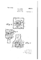
- Figure 1 is an elevational view of a streetcrossing traffic-signal equipped with and embodying my present invention
- Figure 2 is a fragmentary vertical sectional view of the upper portion of the signal-structure 4
- Figure 3 is a horizontal sectional view taken approximately on the line 33, Figure 2.
- Figure 4 is a horizontal sectional view through the base portion of the signal-standard, taken approximately on the .line 4 4, Figure 1;
- Figure 5 is a fragmentary Vertical sectional view through the base portion of the signal standard.
- Figure 6 is a fragmentary vertical sectional view through the upper portion ot a slightly modiied signabstructure also the four sides of which compartments are translucent panels of glass or other suitable material.
- the particular structure described is for a four-wa signal, that is to say, the signal is adapte for use at the intersection of two fares on each of which traic moves in opposite directions, or, in other words, such thoroughfares are two-wa as distinguished from oneway thorough ares. Consequently.
- the end panels or walls 8 upon two adjacent sides of the top or uppermost compartment 7 are preferably red in color and have painted or otherwise visually exposed thereon the signal word or indication sto while the end panels or walls 8 of the ot er two adjacent sides of the compartment 7 are preferably of green or other contrasting cross thoroughor walls 10 of the intermediate or middle 'color and have painted or otherwise visually exposed thereon the signal word or indication go.
- the end panels or walls 9 of the bottom or lowermost compartment 5 are also of contrasting color and have in like manner visually exposed thereon the respective signal words or indication stop and"go, the end panels compartment 6 being all preferably white in color and displaying the signal-word or indication wait, all as best seen in Figure l.
- thesignal words or indication traffic change or any equivalent wording or legend maybe used in place of the indication Wait on the panels 10, and the coloring of the panels of the several compartments may be varied as desired, but, in any sense, the 'panels of the respective compartments should preferably be in distinguishing colors.
- the illumination of the respective panels 8, 9, and 10 is regulated and controlled automatically in timed relation by a drum 12 mounted forA rotation upon bearing-standards 13 and whose usually horizontally disj posed shaft is provided with a gear 14 having meshing driven engagement with a pinion 15 suitably driven through reductionbox mechanism 16 by an electric or other suitable motor 17.
- the particular means formaking5 and breaking the electrical circuits is quite obvious in a signal device of the character described, and inasmuch as the same doesnot enter into the present invention, except in a general way, suoli means is only shown conventionally in the drawmgs.
- a relatively small miter-gear 25 whichv meshes with a like ear 26 on a cross-shaft 27.
- a larger miter-gear 28 On the shaft 2 adjacent the gear 26, is a larger miter-gear 28,/ which meshes with two'similar gears 29, 30, on the inner ends, respectively, of two cr ss stub- ,liashed and shafts 31, 32, extendingin axial alignment with each other and at right angles to the shaft 27.
- arms 33 On the ⁇ ends of the shaft 27 are two arms 33 each having an arrowhead or other suitable indicating device 34 at their free ends.
- arms 35 On the outer ends of the stub-shafts 31, 32, are similar arms 35 each having on their ends an arrow-head or other device 36.
- the arms 33 and 35 are located near the inner faces of the panels 8, 9, and 10, and to permit rotation thereof, as will be presently set forth, slots 37 are provided in the horizontal partitions 3 and 4.
- the drum 12 is rotated, the shaft 24, through the intermediary of the gearing between it and the shaft of the drum, is rotated therewith.
- the shafts 27, 31, and 32 are, of course, rotated in turn from the shaft 24 by the arrangementsof gearing which co-operates with the miter-gear 25 at the upper end of the shaft 24. Consequently, the arms 33 and 35 are accordingly rotatably swung with their respective shafts, and the arrow-heads 34 and 36 caused to travel in a circular orbit or path just inside of the glass panels of the respective compartments 5, 6, and 7.
- the colored panels 8 and 9 are provided with arcuate portions 38 and 39, respectively, which are uncolored, or at least of a distmguishing color from that of the panels, and such arcuate portions are preferably translucent or transparent to visually expose arrow-heads 34 and 36 therethrough.
- the movement of the arrow-heads 34 and 36 is obviously synchronized with the timing' of the illumination of the respective signal indications.
- the arrow-head 36 displayed upon one side of the standard or post travels clock-wise, it appears to view at the lower left-hand side of the upper panel 8 on which the indication stop is displayed just at the moment that particular indication is flashed or signalled. It then travels through the arc of the portion 38 during the period of display, and passes therefrom at the termination of the period.
- the same advantage o tains when the driver is approaching the signal and it is set for go, for the timing and gradual expiration period which is sequentially of the period is indicated and visually sig- 33, is mounted, is proportioned and timed I nalled by the arrow, and should he arrive so as to be in synchronism with the conat the signal just about the time the arrow is trolling devices for illuminating the respecpassing from the arcuate portion 39 to the tive signal indications of stop, go, middle panel, he has ample warning that the wait, and the like.
- the invention contemplates the utilizathe relatively shorter interval of the oltion of either mechanical or electrical oplowing wait period in which to clear the eration of the device, either partially or as crossing; or, if he is a, careful driver and a whole, and it is obvious that changes in observes that he is liable to be blocked or the construction and arrangements of the delayed from any cause in making the crossdevices may be made in many respects with 55 ing before the go indication is set for the out in the least departing from the spirit of cross-direction, he will come to a stop and;j the invention as defined in the appended await the termination of the following' claim. stop indication in his direction.
- the rotatover the tralic indicating end walls of all ing indicator ofthe resent invention may said compartments, and means comprising be operated mechanlcally in synchronism shafts and gearing intermediate the indiwith the electrical illumination control as cator and the drum for effecting synchrodescribed, but to minimize cost of installanized rotary movement of the indicator with tion and maintenance, or where it is not the rotary illuminating movement of the convenient to so equip Ithe structure, the rodrum for
Landscapes
- Physics & Mathematics (AREA)
- General Physics & Mathematics (AREA)
- Illuminated Signs And Luminous Advertising (AREA)
Description
Sept. L M28. 1,682,753 G. L. HARRIS -TRAFFIC SIGNAL Filed Nov. 2, 1925 2 Sheets-Sheet 1 Sept. 4, 1928 G. 1L.. HARRIS TRAFFIC SIGNAL Filed Nv. 2, 1925 sheets-sham 2 F for when it is time `UNITEDA STATES PATENT OFFICE.
GUSTA'V' L. .HABRI OF ST. LOUIS, MISSOURI.
TRAFFIC SIGNAL.
Application lecl November 2, 1925. Serial No. 66,236.
lllhis invention relates generally to signaling devices and, more particularly, to a certain new and useful improvement in signaling devices especially of the type designed for regulating or controlling street or thoroughfare traiiic.
Signaling devices of the type mentioned are now generally located at street-crossings and usually comprise,
as far as I am aware, stop, Wait, and' go signs that automatically are tially illuminated, being in effective visual determined its a matter of safety,
intermittently and sequenthe respective indications display during preand regulated' periods of time.
it is important that the signal indications or signs be observed promptly upon throughout the At street intersections the displayal full effective thereof and display period. or crossings, especially where traiiic is relatively heavy, it is particularly necessary, collisions and accidents,
in the avoidance of that the .duration of the eective display periods 'of the traiiic indications be carefully of traiiic from one other, traiiic on the one rbe stopped promptly,
observed and obeyed, to change movement thoroughfare to the thoroughfare should while traiiic on the cross thoroughfare should be as promptly started, and vice versa; and there should be a slight pause between the stop and go periods by the observance of the wait lor trailic change crossing of vehicles indication to clear. the that may have passed the signal on the then displayed go indication and just before the stop indication is displayed against traffic in that particular direction and also before period of the stop lag ainst traiiic in the cross The present invention has the display indication then set direction is ended.
for its principal object the provision in connection with a signaling-structure of the type mentioned of an indicator correlated to and' operating synchronously with the dications so that gradual expiration of periods may proaching or respective signal-inthe timing and sequential the respective vbe visually signalled stationary traiiic, whereby the display to appossibility of error in' observance of the re- .s ective indications is greatly minimized and lie eiiiciency and effectiveness ofthe signal as a whole greatly increased.
And with the above. view, my invention resi and other objects in des in the novel features of form, construction, arran ement, and combination of parts here'ina ter described and pointed out in the claim.
In the accompanying drawings,-
Figure 1 is an elevational view of a streetcrossing traffic-signal equipped with and embodying my present invention;
Figure 2 is a fragmentary vertical sectional view of the upper portion of the signal-structure 4 Figure 3 is a horizontal sectional view taken approximately on the line 33, Figure 2.
Figure 4 is a horizontal sectional view through the base portion of the signal-standard, taken approximately on the .line 4 4, Figure 1;
Figure 5 is a fragmentary Vertical sectional view through the base portion of the signal standard; and
Figure 6 is a fragmentary vertical sectional view through the upper portion ot a slightly modiied signabstructure also the four sides of which compartments are translucent panels of glass or other suitable material.
I might here state that the particular structure described is for a four-wa signal, that is to say, the signal is adapte for use at the intersection of two fares on each of which traic moves in opposite directions, or, in other words, such thoroughfares are two-wa as distinguished from oneway thorough ares. Consequently. the end panels or walls 8 upon two adjacent sides of the top or uppermost compartment 7 are preferably red in color and have painted or otherwise visually exposed thereon the signal word or indication sto while the end panels or walls 8 of the ot er two adjacent sides of the compartment 7 are preferably of green or other contrasting cross thoroughor walls 10 of the intermediate or middle 'color and have painted or otherwise visually exposed thereon the signal word or indication go. In a similar manner, the end panels or walls 9 of the bottom or lowermost compartment 5 are also of contrasting color and have in like manner visually exposed thereon the respective signal words or indication stop and"go, the end panels compartment 6 being all preferably white in color and displaying the signal-word or indication wait, all as best seen in Figure l. Obviously, thesignal words or indication traffic change or any equivalent wording or legend maybe used in place of the indication Wait on the panels 10, and the coloring of the panels of the several compartments may be varied as desired, but, in any sense, the 'panels of the respective compartments should preferably be in distinguishing colors.
The illumination of the respective panels 8, 9, and 10 is regulated and controlled automatically in timed relation by a drum 12 mounted forA rotation upon bearing-standards 13 and whose usually horizontally disj posed shaft is provided with a gear 14 having meshing driven engagement with a pinion 15 suitably driven through reductionbox mechanism 16 by an electric or other suitable motor 17. Disposed on drum '12, is a suitable arrangement of electrical contact elements 18, which co-operate with terminal contact elements 19 for the respective circuits of the lights 11. The particular means formaking5 and breaking the electrical circuits is quite obvious in a signal device of the character described, and inasmuch as the same doesnot enter into the present invention, except in a general way, suoli means is only shown conventionally in the drawmgs.
So far as' the present invention is concerned, constructions and arrangements of signal devices other than that specifically shown and described can be as well embodied therewith, but, for illustration, the structural featuresl of my invention will now be explained in connection with the described structure. Meshing with the gear 14, is a similar gear 20 fixed .on a shaft 21 mounted on the standards 13 for rotation above the drum 12. On the shaft 21, is a miter-gear 22 meshing with another like gear 23 onV the lower end-portion of a vertically disposed shaft 24 extending up through the hollow post 1.
At the upper end of the shaft 24, which terminates'.l preferably in the middle compartment 6, is a relatively small miter-gear 25, whichv meshes with a like ear 26 on a cross-shaft 27. On the shaft 2 adjacent the gear 26, is a larger miter-gear 28,/ which meshes with two'similar gears 29, 30, on the inner ends, respectively, of two cr ss stub- ,liashed and shafts 31, 32, extendingin axial alignment with each other and at right angles to the shaft 27.
On the` ends of the shaft 27 are two arms 33 each having an arrowhead or other suitable indicating device 34 at their free ends. On the outer ends of the stub- shafts 31, 32, are similar arms 35 each having on their ends an arrow-head or other device 36.
The arms 33 and 35 are located near the inner faces of the panels 8, 9, and 10, and to permit rotation thereof, as will be presently set forth, slots 37 are provided in the horizontal partitions 3 and 4.
l/Vhen the drum 12 is rotated, the shaft 24, through the intermediary of the gearing between it and the shaft of the drum, is rotated therewith. The shafts 27, 31, and 32, are, of course, rotated in turn from the shaft 24 by the arrangementsof gearing which co-operates with the miter-gear 25 at the upper end of the shaft 24. Consequently, the arms 33 and 35 are accordingly rotatably swung with their respective shafts, and the arrow-heads 34 and 36 caused to travel in a circular orbit or path just inside of the glass panels of the respective compartments 5, 6, and 7.
Coincident with the paths of the 'arrowheads 34 and 36, the colored panels 8 and 9 are provided with arcuate portions 38 and 39, respectively, which are uncolored, or at least of a distmguishing color from that of the panels, and such arcuate portions are preferably translucent or transparent to visually expose arrow-heads 34 and 36 therethrough.
By proportioning the gearing, the movement of the arrow-heads 34 and 36 is obviously synchronized with the timing' of the illumination of the respective signal indications. Thus, for example, assume the arrow-head 36 displayed upon one side of the standard or post travels clock-wise, it appears to view at the lower left-hand side of the upper panel 8 on which the indication stop is displayed just at the moment that particular indication is flashed or signalled. It then travels through the arc of the portion 38 during the period of display, and passes therefrom at the termination of the period. B y observin this arrow, the driver of a vehicle stopped y the signal is enabled to note just how lono' the particular indicason has been in eiet, lad it is particularly advantageous to him should he arrive at the signal just about the moment the display period is ending, for he may pre are for the starting of his vehicle and ma e a prompt get-away after the termination of the Wait is of relatively shorter duration than the sto and go periods. The same advantage o tains when the driver is approaching the signal and it is set for go, for the timing and gradual expiration period which is sequentially of the period is indicated and visually sig- 33, is mounted, is proportioned and timed I nalled by the arrow, and should he arrive so as to be in synchronism with the conat the signal just about the time the arrow is trolling devices for illuminating the respecpassing from the arcuate portion 39 to the tive signal indications of stop, go, middle panel, he has ample warning that the wait, and the like. go" period is ending and that he only has The invention contemplates the utilizathe relatively shorter interval of the oltion of either mechanical or electrical oplowing wait period in which to clear the eration of the device, either partially or as crossing; or, if he is a, careful driver and a whole, and it is obvious that changes in observes that he is liable to be blocked or the construction and arrangements of the delayed from any cause in making the crossdevices may be made in many respects with 55 ing before the go indication is set for the out in the least departing from the spirit of cross-direction, he will come to a stop and;j the invention as defined in the appended await the termination of the following' claim. stop indication in his direction. Having thus described my invention,
In cases of one-way thoroughfares or on what I claim and desire to secure by Let- 50 two-way thoroughfare where it is desirable ters Patent is: to place signals on the corners instead of In a traffic-signal, in combination, ahousthe center of the intersections, the structure ing, transverse partitions'within the housing may be suitably modified. Such a moditicadividing the housing into a plurality of tion is illustrated in Figure 6, wherein the superposed compartments, said .partitions 05 housing 2 on the post or standard 1 has being slotted ,for communication one with three compartments 5', 6 and 7', in only another, trai'ic indications upon an end one wall of which are provided the transluwall of said compartments, electrical means cent panels 8, 9, and l0. In the case of oneincluding a rotating contact-drum for ilway trailic, there will, of course, be only two luminating said indications in sequential signal stands, one at each of thetwo near periods of predetermined duration, an inright-hand corners for traiic approaching dicator having its axis of rotation located the intersection, while in the case of twowithin the central compartment and adaptway traiiic there will be four of the signal ed for travel in a circular path consecutivestands, one at each of the four near rightly through said communicating slots and hand corners.A In these instances, the rotatover the tralic indicating end walls of all ing indicator ofthe resent invention may said compartments, and means comprising be operated mechanlcally in synchronism shafts and gearing intermediate the indiwith the electrical illumination control as cator and the drum for effecting synchrodescribed, but to minimize cost of installanized rotary movement of the indicator with tion and maintenance, or where it is not the rotary illuminating movement of the convenient to so equip Ithe structure, the rodrum for visually signalling the eiective tating indicator may be electrically operduration and gradual expiration oi the reated, and in such cases a separate electrical spective periods. or other motor 40 may be employed as In testimony whereof, I have signed my 85 shown in Figure 6, the gearing 41 between name to this specification.
the motor and the shaft 42 on which the arm 33, corresponding to the described arm GUSTAV L. HARRIS.
Priority Applications (1)
| Application Number | Priority Date | Filing Date | Title |
|---|---|---|---|
| US66236A US1682753A (en) | 1925-11-02 | 1925-11-02 | Traffic signal |
Applications Claiming Priority (1)
| Application Number | Priority Date | Filing Date | Title |
|---|---|---|---|
| US66236A US1682753A (en) | 1925-11-02 | 1925-11-02 | Traffic signal |
Publications (1)
| Publication Number | Publication Date |
|---|---|
| US1682753A true US1682753A (en) | 1928-09-04 |
Family
ID=22068178
Family Applications (1)
| Application Number | Title | Priority Date | Filing Date |
|---|---|---|---|
| US66236A Expired - Lifetime US1682753A (en) | 1925-11-02 | 1925-11-02 | Traffic signal |
Country Status (1)
| Country | Link |
|---|---|
| US (1) | US1682753A (en) |
Cited By (1)
| Publication number | Priority date | Publication date | Assignee | Title |
|---|---|---|---|---|
| US20090051567A1 (en) * | 2007-04-27 | 2009-02-26 | Wabeke Roger L | Highway intersection hazard warnings and traffic control system, and method of applying same |
-
1925
- 1925-11-02 US US66236A patent/US1682753A/en not_active Expired - Lifetime
Cited By (2)
| Publication number | Priority date | Publication date | Assignee | Title |
|---|---|---|---|---|
| US20090051567A1 (en) * | 2007-04-27 | 2009-02-26 | Wabeke Roger L | Highway intersection hazard warnings and traffic control system, and method of applying same |
| US7573401B2 (en) * | 2007-04-27 | 2009-08-11 | Wabeke Roger L | Highway intersection hazard warnings and traffic control system, and method of applying same |
Similar Documents
| Publication | Publication Date | Title |
|---|---|---|
| US5726648A (en) | Time indicating traffic light | |
| US3200218A (en) | Safety traffic signal lights | |
| US1682753A (en) | Traffic signal | |
| US2480290A (en) | Luminous time lapse traffic signal | |
| US2683868A (en) | Traffic control system | |
| US2006675A (en) | Traffic signal | |
| US2252339A (en) | Driving signal for vehicles | |
| US2254676A (en) | Traffic signal | |
| US1628756A (en) | Signaling device | |
| US1885776A (en) | Combined street and traffic sign | |
| US1567871A (en) | Traffic-signaling system | |
| Forbes et al. | Effectiveness of symbols for lane control signals | |
| US1846987A (en) | Traffic signal | |
| US2049002A (en) | Traffic signal | |
| US1795448A (en) | Traffic signal | |
| DE855064C (en) | Traffic lights recognizable for color-blind people | |
| US1632211A (en) | Traffic signal | |
| US2119049A (en) | Traffic semaphore | |
| US1942306A (en) | Traffic signal | |
| US1988633A (en) | Traffic signal | |
| US1553730A (en) | Semaphore for automobile and like traffic | |
| US2490585A (en) | Electrically operated time lapse traffic signal | |
| US1852989A (en) | Traffic signal | |
| US1224657A (en) | Direction-indicator for automobiles. | |
| US1918327A (en) | Traffic signal |