US1668024A - Fare begister - Google Patents
Fare begister Download PDFInfo
- Publication number
- US1668024A US1668024A US1668024DA US1668024A US 1668024 A US1668024 A US 1668024A US 1668024D A US1668024D A US 1668024DA US 1668024 A US1668024 A US 1668024A
- Authority
- US
- United States
- Prior art keywords
- arm
- devices
- fare
- indicator
- shaft
- Prior art date
- Legal status (The legal status is an assumption and is not a legal conclusion. Google has not performed a legal analysis and makes no representation as to the accuracy of the status listed.)
- Expired - Lifetime
Links
- 238000007639 printing Methods 0.000 description 124
- 239000011435 rock Substances 0.000 description 36
- 240000006802 Vicia sativa Species 0.000 description 32
- 239000000969 carrier Substances 0.000 description 20
- 230000002093 peripheral Effects 0.000 description 20
- 230000000875 corresponding Effects 0.000 description 12
- 238000010276 construction Methods 0.000 description 10
- 210000001331 Nose Anatomy 0.000 description 6
- 230000001965 increased Effects 0.000 description 6
- 230000000994 depressed Effects 0.000 description 4
- 230000000717 retained Effects 0.000 description 4
- 230000000153 supplemental Effects 0.000 description 4
- AGPKZVBTJJNPAG-CRCLSJGQSA-N D-allo-isoleucine Chemical compound CC[C@H](C)[C@@H](N)C(O)=O AGPKZVBTJJNPAG-CRCLSJGQSA-N 0.000 description 2
- FHIVAFMUCKRCQO-UHFFFAOYSA-N Diazinon Chemical compound CCOP(=S)(OCC)OC1=CC(C)=NC(C(C)C)=N1 FHIVAFMUCKRCQO-UHFFFAOYSA-N 0.000 description 2
- 210000002683 Foot Anatomy 0.000 description 2
- 241000219171 Malpighiales Species 0.000 description 2
- 240000007673 Origanum vulgare Species 0.000 description 2
- 239000004020 conductor Substances 0.000 description 2
- 230000003247 decreasing Effects 0.000 description 2
- 238000006073 displacement reaction Methods 0.000 description 2
- 230000000694 effects Effects 0.000 description 2
- 229920000591 gum Polymers 0.000 description 2
- 238000003780 insertion Methods 0.000 description 2
- 235000013372 meat Nutrition 0.000 description 2
- 239000002184 metal Substances 0.000 description 2
- 230000004048 modification Effects 0.000 description 2
- 238000006011 modification reaction Methods 0.000 description 2
- 229920000136 polysorbate Polymers 0.000 description 2
- 230000036633 rest Effects 0.000 description 2
- 230000002441 reversible Effects 0.000 description 2
- 238000004804 winding Methods 0.000 description 2
Images


Definitions
- This invention relates to registers and while it has been designed primarily for use as a fare register on passenger carriers, such as inter-urban traction lines and suburbanrailways, it may he used in connection with registers of various kinds such as cash registers, for example, and for various other purposes.
- One object of the invention is to provide a register which may he quickly and easily set and operated to indicate and record cash fares of any amount from one cent up to relatively large amount and paper fares of various kinds.
- a further object of the invention is to provide a register which can he set to indicate in penny multiples fares of relatively large amounts and requiring the setting of three digits on the indicator, by the use of but two operating, or setting, devices.
- a further object of the invention is to provide such a register which will indicate and record the zone, or section of the route, in which a fare is collected.
- a further object of the invention is to provide a register which will indicate and record the amount of the tarereceived, the zone in which it is receivet. the direction in which the vehicle is travelling and the numher of passengers, and which willbe simple in its construction and positive in its operation and which will be so constructed as to insure the accuracy of the record.
- a further object of the invention is to provide such a device which will print on the record, in addition, to the other items relating to the tare, the date on which the record is made.
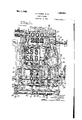
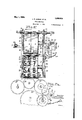
- Fig. l is a front elevation. partly broken aw y, and with the casing rcn'ioved, oi a register embodying our invention; F 2 is a rear elevation vof-the same; Fig. 3 is an elevation of one side of such a register: Fig. l is an elevation of the oth r side of such a re 'ister; Fig. 5 is a section taken on the line 5-5 of Fig. 1; Fig. 6 is a horizontal section showing the fare indicating devices in plan; Fig. 6 is a diagran'nnatic view of the gearing shown in Fig. 6; Fig. 7' is a horizontal sec- Selial No. 535,039.
- Fig. 15 is a tacsimile of a portion of a record produced by the register.
- This indicater comprises two indicating devices which are separately operable and one of which carries one series of: digits and the other of which carries two series of digits, the digits being so arranged that by the proper adjustment of the two indicating devices they may be grouped to indicate any desired tare within the limits named.
- Two operating devices are provided which are connected with the respective indicating devices in such a manner that the latter may be quickly and easily adjusted to bring the desired digits into indicating position.
- each indicating device which constitute the fare indicator, may be of any suitable character and each may comprise one or more members.
- each indicating device as comprising a tape 1 preferably of metal and having thereon the desired indications. These tapes pass about drums 2 rotatably mounted on a shaft 3 carried by a supplemental frame 4 which is mounted within a main frame 5. V /hile the tapes may be moved about the indicating drums 2 in various ways we prefer to connect each tape at one end with the corresponding passes, transfers and the like.
- a similar drum 6 mounted in the frame 4 in the rear of the drum 2 and to provide means for actuating these drums in unison so that the tape may, at the will of the operator, be wound onto one drum and off the other.
- the right hand tape in Figs. 1 and 14 is provided with the digits 0 to 9, inclusive. and with further symbols to indicate paper fares, such as The digits on this tape constitute the units digits of the fares indicated.
- the arrangement of the indi cating devices and of the several series of digits with relation thereto is such that the desired fare may be indicated by the usevof two operating devices only, thus overcoming the diificultiesexperienced with registering large fares in penny multiples where three separate indicating devices are employed and three separate operating devices used for actuating the same, and also avoiding the slowness of operation which results from transferring an amount from a unit indicating device to tens and .hundreds indieating devices.
- the setting, or operating, devices for actuating the indicating devices may be of any suitable kind.
- the shaft 7 has. secured thereto a gear 9, see Figs. 2, 5 and 6 which meshes with an idle gear 10 which in turn meshes with a gear 11, which is connected with the drum 6 on the right hand side of Fig. 2, that is, the tens and hundreds drum.
- the shaft 8 has'secured thereto a gear 12' which meshes with an idle gear 13 which in turn meshes with a gear 14: on the units drum.
- each drum Secured to each drum is a gear 15 meshing with an idle gear 16 which in turn meshes with a gear 17 on the respective front, or indicating, drums, 2, the ratio of these gears being such that the drums are rotated at the same speed so that the tape will be wound onto and off the same uniformly.
- a tightening device may be provided for causing the tapes to fit snugly about the indicating drums and,
- rock arms 18 are pivotally mounted on the shaft 7 and provided at their inner ends with a roller 19 which rests upon the tapes between the two drums, thus taking up any slack that there may be in the tapes.
- the operating, or setting, shafts 7 and 8 may be actu- 'ated in any convenient manner but the actuatmg devices are not here shown; However, the shafts are adapted to be connected at either end'with operating rods which run lengthwise through the car, or to the conductors station where all the fares are collected at one point. These rods are rotatable and may be quickly and easily operated to set the indicator.
- the machine is designed to print a record of each fare registered or indicated on the fare indicator and we have, in the present machine, provided twotype wheels, 20 and 21, the type wheel 21 hearing one series of digits and paper fare indications corresponding to the units indicating device, and the type wheel 20 hearing two series of digits corresponding to the tens and hundreds indicating device.
- the two type wheels are .mounted on a shaft 22 for independent rota-.
- the type wheel 20 has secured thereto a gear 23 which meshes with p a gear 24 on a shaft 25 with which is connected a gear 26 meshing with an idle gear 10 which in turn meshes with the gear 11 connected with the rear drum 6 of the tens and hundreds indicating'device, thus causing the type wheel 20 to rotate in unison with the tens and hundreds indicating device.
- the type whe'el 21 has secured there-- to a gear 28 similar to the gear 23 and which meshes with a gear 29 on the shaft 25, the gear 29 having secured'thereto a. gear 30 which meshes with an idler 27 in turn in mesh with thegear 14 of the unit drum 6, thus causing the type wheel 21 to be rotated in unison with the units indicating device.
- the register is also provided with a passenger counter. or indicator, which indicates the number of passengers carried on each trip.
- this counter comprises three indicator wheels 31 mounted on the shaft 32 and each bearing the digits 0 to 9, inclusive.
- the units counter wheel is coir nected with the tens counter wheel and the tens counter wheel is connected with the hundreds counter wheel by ordinary transfer mechanism so that the count is trans ferred from one counter tothe other,
- the units counter wheel may be actuated in any suitable manner but as here shown it has secured thereto a ratchet wheel (Fig. with which cooperates a pawl 34 carried by an arm 35 pivotally mounted on the axis of the shaft 82.
- Thispawl arm 35 is operated by a suitable actuating device which is preferably in'the form of a slide bar 36 mounted in a suitable guideway 37 in the rear portion of the frame and at one side of the indicating devices.
- the slide bar is utilized to operate other parts of the mechanism and has a movement greater than is necessary for the operation of the passenger counter and we, therefore, have interposed. between the slide bar and the pawl arm suitable mechanisn'i which will cause a portion only of the movement of the slide bar to be transmitted to the pawl arm.
- a second arm 38 (Figs.
- the arm 38 has an extension 41 provided with a finger 1-2 adapted to engage a pin 43 on the arm when upward movement is imparted to the arm 38.
- the finger -12 is normally spaced a considerable distance from the pin 43 and, consequently, movement will not be transmitted to the pawl arm until the slide bar has completed a portion of itsmovcment, after which the finger will engage the pin and the pawl arm will be operated to advance the units counter wheel.
- the slide bar may be actuated in any suitable manncr but, as here shown, it is moved in one direction by a cord std connected with the lug, or bracket, and adapted to extend through the car or to the operators station alongside of the setting rods.
- the slide bar is nioved in the opposite direction by means of a spring to also connected with the lug e0.
- the passenger counter is reset at the end of each trip and to this end the counter wheels are loosely mounted upon the shaft 32 and are provided with ,pawls 4E6 adapted to be engaged by a one tooth ratchet wheel carried by the shaft and which is, in the present instance, formed by cutting a notch 4.7 in the shaft itself, so :that the rotation of the shaft :will cause this tooth to engage the pawls and carry the counter wheels to their zero positions.
- the resetting shaft 32 is operated by means of a gear t8 rigidly secured thereto and meshing with a pinion 49 carried by a shaft 50 which is mounted in the frame of the machine for both sliding and rotatory movement and is provided on its outer end, beyond the casing in which the machine is enclosed, but which is not here shown.
- the passenger record is also printed on the recordstrip along with the amount of the fare but in the present machine this passenger record is never reset and, therefore, constitutes a total passenger counter, or what may be termed a consecutive numbering device, as each record will bear a number one higher than the preceding record, but this number is also an accurate count of the total number of )assengers carried.
- a series of type wheels 55 are mounted on a shaft 56 and each type wheel is provided with a gear 57 which meshes with a gear 53, on a shaft 59 (Figs. 3 and 7).
- the gear for the units type wheel has connected therewith a ratchet wheel 60 adapted to be actuated by a pawl 61 mounted on an arm 62 which is journaled on the axis of the shaft 59 and extends between two pro jections 63 and 6% on the slide bar 36. Consequently, upon each upward movement of the-slide bar the pawl arm 62 will be elevated by the projections 63 and upon the downward movement of the slide bar the arm will be engaged by the projections 6 and actuated to advance the gear 58 and the units type wheel one space. Suitable transfer mechanism transfers the count from the units wheel to the other type wheels.
- each of the drums 2 of the fare indicating device has secured thereto a toothed disk (35, the teeth of which are spaced apart to form 'ecesses adapted to receive a projection or roller 66 carried by a rock arm 67 pivotally mounted on the frame at 68.
- the arm is normally free to move about its axis and as the drum is rotated the roller 66 will ride over the teeth of the disk ()5 and will offer but little resistance to the rotation of the drum.
- the locking arm 67 is moved into and held in fixed engagement. with the disk during the operation of the registerin mechanism by means of an arm 268 (Fig. 5 pivotally mounted at 69 and having a part arranged to engage the holding arm 67 when the arm 268 is rocked about its axis,
- the engaging part of the arm 268 is in the form of a screw 70 extending through the arm 268 and held in adjusted position with relation thereto by means of a nut 71.
- aplate, or arm, 72 having a cam shaped edge 70 arranged to be engaged by a pin 74 carried by an arm 75 secured to and forming an extension of the arm 38 which operates the passenger counter.
- the arrangement of the cam is such that when the slide bar operated the pin 7 L will act on the edge of the plate 72 to rock th latter about its axis and thus move the arm #68 into engagement with the holding arm 67, thereby forcing the roller 66 into the adjacent recess, and, if the recess has not been in perfect alinement with the roller, adjusting the plate 65 to bring the recess into line with the roller and thus bring the indicating drum and tape into the correct indicating-position.
- the cam plate 7 2 is provided with a dwell, or curved surface, 76 so arranged that when the plate has been advanced by the operation of the pin 74 the surface 76 will lie substantially concentric with the axis about which the pin moves so that the pin is permitted to continue its movement but will hold the plate72 in its forward position, thus retaining the holding arm 67 and roller 66 in locking engagement with the disk 65 throughout the movement of the slide bar.
- the mechanism as a whole included in a casing which is provided with sight openings through which the various indicators are visible, these open-. ings being so arranged that they will show but one indication oncach'indicator. t is desirable that this sight opening should be closed cluriiigtlie adjustment of the indicators and .for this purpose we have provided the fare indicator with a flash, of blind, 77 carried .by arms 78 pivotally mounted on the'axis of the drums 2 and adapted to be moved into a position in line with the sight opening whenever setting movement is imparted to the fare indicating devices and to be retained in that position until the fare has been registered.
- the flash bears the words Not registered, thus showing that so long as the flash, is in its operative position the fare has not been registered.
- the flash is moved into its operative position by the movement imparted to either of the holding arms 67 by the rotation of the corresponding drum 2. This is accomplished by means of links 7 9 each of which is connected at one end with an arm 67 and has at lts other end a slot- 80 to receive a pin 81 carried by one of the arms 78 of the flash.v
- the arrangen'icnt is such that the first movement of the drum which will cause the roller 66 to ride over one of the teeth of the plate 65 will elevate the flash.
- the flash is held in its elevated position by means of a (latent 8&2 pivotally mounted at 83 and arranged to engage a shoulder 8% on the hub of one of the arms 78 of the flash. Because of the slotted connection between the link 79 and the flash, the holding arm 6? is free to rise and fall during the continued movement of the drum without altering the position of the flash.
- a trip arm 85 is secured to the detent 82 and is arrangcd'to be actuated by the slide bar just before the latter completes its up ward movement.
- the rear end of the trip arm lies just above an actuating arm 86 for the tapper 87 of a bell 69 which sounds an audible signal whenever the o 'ierating mechanism is operated.
- the actuating arm 86 for the bell t-apper lies in the path of a project-ion 90 carried by the slide bar and so arranged that it will operate the actuating arm to retract the tapper and will release the same to permit the tapper to operate justbefore the slide bar completes its upward movement.
- the register is also provided with means to indicate and print the number of the zone,- or section of the route, in which the vehicle is travelling at the time the fare is registered.
- the indicating device preferably comprises one or more indicating drums, depending upon thenumloer of Zones. In the present instance there are two zone indicating drums, a units drum 91 and a tens drum 92, both of which are mounted on a shaft provided at one end, beyond the casing which encloses the machine, with one or more actuating arms 94 adapted to be con nected with a cord, or cords, extending through the car. As shown in the drawings, F 1g.
- the indicator drums 91 and 92 are connected by suitable transfer mechanism so that the count will be transferred from the units down to the tens drum.
- the units drum is mounted on a sleeve 95 journaled on the shaft 93 and the tens drum is rotatably mounted on Secured to the units drum" the sleeve.
- 7 (Figs. 7 and 10) is a ten tooth gear 96 llu which meshes with a similar gear 97 on the transverse shaft 98.
- Rigidly secured to the gear 97 is a one toothed gear 99 adapted to engage the teeth of a ten tooth Geneva gear 100 secured to the tens indicator wheel, thus causing the latter to be advanced one point for each complete rotation of the units counter wheel.
- type wheels 101 and 102 are mounted in axial alinement with the type wheels 55 and the units printing wheel has secured thereto a ten tooth gear 103 which meshes with the ten tooth transfer gear 97 and the tens printing wheel has secured thereto a ten tooth Geneva gear 104 adapted to be engaged by a one toot-h gear 105 mounted on the transverse shaft 98 and secured to the ten tooth gear 97.
- a suitable pawl and ratchet mechanism which, as here shown, comprises a ratchet wheel 106 (Fig. 9) rigidly secured to the sleeve 95 and adapted to be actuated by a pawl supported by the shaft 93.
- the pawl is a double nosed pawl which is reversible to enable the ratchet wheel to be operated in either direction, the teeth of the ratchet wheel being shaped to permit such operation.
- an arm 107 is rigidly secured to the shaft 93 and has pivotally mounted thereon a pawl 108 having at each end thereof a nose.
- the pawl is pivoted at 109 and is provided adjacent to said pivot with a projection 109 with which cooperates a holding device, such as a roller 110, carried by an arm 111 .pivotally mounted on the outer end of the pawl carrying arm 107 and acted upon by a spring 112 which holds the roller in engagement with the pawl and the projection thereon.
- the roller will engage on one side of the projection 109 and yieldingly hold one nose of the pawl in engagement with the ratchet wheel and when the pawl is in the other position the roller will engage the other side of the projection and yieldingly hold the other nose of the pawl in engagement with the ratchet wheel.
- a spring 113 tends to move the pawl arm 107 in one direction and it is moved in the opposite direction by the actuating arms 94 on the shaft 93. Consequently, a rocking movement imparted to the shaft 93 will cause a similar movement to be imparted to the ratchet wheel, the direction of this movement depending upon the position of the pawl 108.
- the pawl may be shifted from one position to the other in any suitable manner but preferably this is accomplished by the resetting of the passenger indicator and in the present instance the direction indicator is utilized for this purpose.
- the direction indicator is in the form of a segmental drum, or curved plate, 114, (Figs. 1, 2 and 4-) plvotally mounted adjacent to the end of the resetting shaft 32, as shown at 115.
- Mounted on the end of the resetting shaft is a pinion 116 which meshes with a gear 117 which carries the pin 119 which projects into a slot 118 in the direction indicator.
- the ratio of the gears 116 and 117 is two to one so that one complete rotation of the resetting shaft will impart a one-half rotation to the gear 117 and thus move the slot 118 from one side of the axis of the gear to the other side of that axis, thereby shifting the direction indicator from one position to the other.
- This direction indicator is connected by means of a pitman 120 with an arm 121 which is rigidly secured to a shaft 122 and the end of which lies beneath a projection 123 on the pawl 108. When the direction indicator is in its lower position and the word North is exposed the pawl 108 will be in the position shown in Fig. 9 and the projec tion 123 of the pawl will overlie the arm 121.
- the projection 123 has a cam surface 124: which will lie in the path of a pin 125 on the pitman 120 when the direct-ion indicator is in its uppermost position so that the downward movement of the direction indicator will cause the pin to engage the cam surface of the projection and force the pawl 108 into its reversed position.
- an arm 126 having connected therewith a detent 127 adapted to be moved into and out of engagement with the teeth of the ratchet wheel by the movement of the respective arms.
- a spring 128 connected with the arms tends to move them in directions to carry the detents into inoperative positions.
- the upper ends of the arms 126 are beveled and are arranged respectively in the paths of pins 129 and 130 carried by the opposite ends of the pawl 108. lVhen the pawl is in the position shown in Fig.
- each tooth is provided at its base with a tapered recess into which the end of the detent extends, thus causing the detent to also sweeti wheels 55, has mounted thereon a type'wheel 131 to print a record of the direction in which the vehicle is moving.
- the type is so arranged upon the type wheel, which may be either a complete wheel or a segment, that the movement of the direction indicator from one position to another will, im-
- a locking device which serves both to prevent the operation of the zone indicating device during the resetting of the passenger counters and to prevent the resetting of the passenger counters when the operating mechanism for the zone indicator has been moved from its normal position.
- this lock comprises a' bar 132 connected at its lower end with a crank arm 133 secured to the shaft 93 and having its upper end arranged adjacent to the lower edge of the plate 52 forming part of the resetting mechanism.
- the actuating device for the zone indicators is operated the upper end of the bar 132 will be moved alongside of the plate 52 so as to hold the same against lateral displacement, thus preventing the plate from being disconnected from thegear 48.
- the operating mechanism for the zone indicators is in its normal position the plate may be moved laterally and this movement will bring it into line with the upper end of the bar 132 and it will thus prevent the movement of that bar and, consequently, will prevent the operation of the operating devices for the zone indicator.
- the rock arm 133 on the shaft 93 also serves to limit the movement of the shaft 93 and to this end it is arranged between two stops 134 secured to an adj acent portion of the frame. 7
- this lock is key controlled and comprises a locking member, or arm, 135 pivotally mounted on the frame adjacent to the guideway 37 and having its lower free end adapted to be moved into and out of the path of the part carried by the slide bar 36.
- the locking member moves into line with the slide bar itself and when in this position prevents the operation of the slide bar.
- Rocking movement is impartedto the locking member by means of a lever 136 pivotally mounted between its ends at 137 and connected at its lower end with a second lever 138 which is pivotally mounted at 139.
- This second lever is acted upon by a key 140 which sets the type to print the identifying mark on the record.
- the type which prints the identifying mark is carried by the key, as shown at 141 (Fig. 13) and the opening in the main frame in which the key is inserted is so arranged that when the key is fully inserted the type will be in printing position.
- the second lever 138 is provided with a projection 142 which lies in the path of a lug, or projection, 143 carried by the key 140. Consequently, when the key is inserted in the slot, or guideway, inthe frame its inward movement will cause the lug to engage the finger 142 and actuate the levers to move the locking member 135 into an inoperative position.
- the key is provided with a second lug 144 arranged in front of and spaced from the lug 143 and this second lug is of such a size that it will just clear the lower edge of the finger 142 when the lever 13Sis in its normal position, that is, with the locking member 135 in operative position. Consequently, when the key is inserted the first lug 144 will pass the finger 142 and the latter will be engaged by the lug 143 and as the lever is moved inwardly the finger will swing down into the recess between the two lugs so that the withdrawal of the key will move the lever outvardly to restore the locking member 135 to its locking position. Consequently, the machine is in its unlocked position only when the key is inserted in the keyway.
- type Wheels 145 arranged in axial alinement with the type wheels 55 and adapted to print the dateon therecord. These type wheels may be of any suitable character and may be operated in any suitable manner. As here shown, they areoperated knobs 146 arranged beyond the casing enclosing the mechanism, in a Well known manner. 2
- Suitable printing mechanism is provided by means of which a printed record may be taken from the several type wheels or printing devices employed in the machine, and this'record' is printed upon each operation of the register so as to provide a record of each individual fare.
- the printing mechanism is carried by' an auxiliary frame 147 comprising two side mom bers pivotally mounted. at their rear ends on the main frame, as shown at 148 (Fig. 8). These frame members are held in their upper, or operative position, by means of arms 149jpivo-tally mounted on the axis of the shaft 56 and having in their rear edges recesses to receive pins 150'carried by the side members 147 of the frame.
- a supporting plate, or arm, 151 and these arms have mounted therein a. shaft 152 on inc which is mounted a platen 252.
- the platen has a portion projecting laterally from the body thereof and constituting the contact portion of the platen which presses the paper into contact with the type wheels.
- the platen is mounted for both a bodily swinging movement with the supporting members 151 and a rocking movement about the axis of the shaft 152.
- the shaft 152 has secured thereto a gear 153 (Fig. which meshes with a rack lo l rigidly secured to one of the side members of the frame 14:7.
- an inking roller 155 is carried by arms 156 mounted on the shaft 152 and acted upon by a spring 157 which tends to move the inking roller toward the type wheels.
- the inking roller should be depressed when the supporting devices move rearwardly in order to maintain it out of contact with the alining devices for the type wheels, which are shown at 158.
- cams 159 on the side members of the frame which engage a shaft 160 which carries the inking roller and which control the position of the inking roller.
- the cams are so arranged that when the supporting members, or carrier, 151 move forwardly the inking roller will travel forwardly and upwardly into contact with the type wheels, thus applying ink thereto.
- the carrier is moved rearwardly the inking roller is depressed and the platen is moved into contact with the type, this being accomplished by the rearward bodily move meat of the platen and its rocking movement about its axis.
- the contact of the platen with the type, or rather with the paper which is interposed between the same and the type takes place when the carrier 151.
- the carrier is in its rearmost position and in order to move the platen away from the type wheels to permit of the further operation thereof the carrier is moved forwardly into the position shown in Fig. 5.
- the carrier may he oscillated by any suitable mechanism but as here shown this movement is imparted to the carrier by pitmen, or connecting bars. 161 which are connected at their forward ends to the carrier, preferably through the medium of the shaft 152, and at their rear ends with disks 163 mounted on a shaft 161. Rigidly secured to the shaft 164 is a pinion 165 (Figs. 2 and 11) which meshes with an idle pinion 166 which in turn meshes vith a pinion 167 on a shaft 168.
- the pinion is loosely mounted on the shaft and has connected thereto a disk 169 carrying a pawl 170 which engages a one tooth ratchet wheel 171 secured to a gear 172 mounted on the shaft 168 when this gear is rotated in one direction.
- the gear meshes with a rack 173 connected with and forming a part of the slide bar 36.
- the total passenger recorder, or consecutive number printing device, 55 is actuated by the slide bar upon the downward, or return, movement of the same. Consequently, the record is printed before the total passenger counter is operated, and for this reason the passenger counter is normally set to print one number in advance of the actual count so that the record taken always shows the exact number of passengers carried. Inasmuch as this counting device is not visible and the record is only taken by the printing mechanism the fact that it is set ahead of the actual count is unin'iportant.
- Means are also provided to prevent the overthrow of the printing mechanism and to bring the same to a stop in a predetermined position.
- a disk or one tooth ratchet wheel 171 having a tooth, or shoulder, 175 with which cooperates a pawl 176 pivotally mounted on the shaft 168 and having connected therewith an arm 177 carrying a roller 178 which bears against the slide bar 36 and so arranged that it will normally hold the pawl 176 out of the path of the shoulder 175 on the disk 174, but will slip off the end of the slide bar and permit the pawl to be moved into the path of the shoulder 175 just as the slide bar completes its upward movement, the movement of the pawl being imparted thereto by a spring 179.
- the IHOYGiDQHtS of the parts are so timed that the pawl will engage the shoulder and check the movement of the shaft just as the printing mechanism rec. hes its final position.
- the paper on which the record is printed is carried in the form of a roll, as shown at 180, and the web of paper 181 is carried upward about a platen, a shield 182 serving to hold the same out of contact with the inking roller, and carried from the platen 'l'orwardly to a rcvinding roller 183 upon which it is wound and which serves as a papcr feeding device.
- a tension device 18st bears on the roll to resist its rotation and thus u'event it from rotating after the movement of the r winding roller has ceased.
- the rewinding roller 183 removably IHI mounted'in the swinging frame 147 and is operatively connected with a shaft 185 journaled in theframe 1 17.
- This-shaft has mounted thereon, near its outer end, a ratchet wheel 186 which is operated by a pawl 1e? carried by a pawl arm 188 pivotally mounted on the axis of the ratchet wheel and this arm is connected by a link 189 with one 01 the supporting members, or
- This segmental plate is connected by a link 191 with an arm 19?. secured to a shaft 193 on the inner end of which is mounted a second arm 19 1 having a roller 195 arranged to bear upon the surrace oi the roll of paper on the rewinding roller, the arrangement being such that as the di eter of the roll inreases the plate 190 will be moved iorwardiy so as to hold the pawl out of engagement with the ratchet wheel for increasing distances.
- the setting of the indicator also actuates the type wheels to more these same numerals into printing position.
- the total passenger, or consecutive number, counter is operated on the reverse stroke of the slide bar and is theretor set one numberin advance ol the actual registration, thereby causing it to print the correct consecutive number for the fare registered and upon the return movement of the slide bar itis advanced one point so as to be ready to print the consecutive number for the next fare received.
- the indicating mechanism may be used, either in part or in its entir ty, iIHlL UGIHlGDtly of the other teatnres ot the mechan sm here illustrated and described.
- this indicating mecha ism may he t modied in a separate device, or an: a, indicator. such as trequeutly empk rd in ronnertion with a fare indie: but is me i independently of the indicate the reg1s recorder so a; trations at points remote irom the recorder.
- a penny-nmltiple fare indicator having three series of digits to indicate respectively units, tens and hundreds. and comprising two independently operable indicating devices, one of which bears one series of digits and the other of which carries two series of digits.
- separate operating devices for the respective indicating devices, type wheels means actuated by the respective operating devices to set said type wheels to print the item indicated by said indicator, printing mechanism to take a record from said type wheels, normally inoperative devices to hold said indicating devices against movement, and means to render said holding devices operative during the printing operat-ion.
- a pennyanultiple "fare indicator having three series oi digits to indicate respectively units, tens and hundreds. and comprising two independently operable indicating devices, one of which bears one series of digits and the other of which carries two series of digits, two type wheels having type corresponding to the digits on the respective indicating devices, two operating devices, each operating device having geared connec tion with one of said indicating devices and its type wheel, printing mechanism to take a record fzom said type wheels, normally inoperative devices to hold said indicating devices against movement, and means to render said holding devices operative during the printing operation.
- a penny-multiple tare indicator having three series of digits to indicate respec/ tively units, tens and hundreds, and comprising two independently operable indicating devices, one of which carries one series of digits and the other oi which carries two series of digits, separate operating devices for the respective indicating devices, type wheels, means actuated by the respective operating devices to set said type wheels and print the item indicated by said indicator, printing mechanism to take a record from said type wheels, means for actuating said printing devices, normally inoperative devices to hold said indicating devices against movement, and means operatedby the actuating means for said printing devices to render said holding means operative.
- a penny-multiple tare indicator having three series of digits to indicate respectively units, tens and hundreds, and comprising two independently operable indicating devices, one of which bears one series of and the other of which arries two series of digits, separate operating devices for the respective indicating devices, type wheels, means actuated by the respective operating devices to set said type wheels to print the item indicated by said indicator, printing mechanism to take a record from said type wheels, a disk secured to each of said indicating devices for rotation therewith and having peripheral recesses, a detent engaging said disk and normally free to move into and out of said recesses as the disk rotates, a device adapted to hold said detent in one of said recesses to prevent the movement of said disk, and an actuating device for said printing mechanism operatively connected with the device which holds said detent in engagement with said disk.
- a penny-multiple fare indicator having three series or digits to indicate respectively units, tens and hundreds, and comprising two independently operable indicating devices, one of which bears one series of digits and the other of which carries two series of digits, separate operating devices for the respective indicating devices, type wheels, means actuated by the respective op erating devices to set said type wheels to print the item indicated by said indicator, printing mechanism to take a record from said type wheels, means for actuating said printing mechanism comprising a slidab le member, a, disk connected with each of said indicating devices for rotation therewith and having peripheral recesses, a rock arm having a part adapted to enter said recessesand normally free to move into and out of sald recesses as said disk rotates, a second rock arm having a part to engage the first arm to hold the same in engagement with said disk, and means operated by said slidable member to move said second rock arm into engagement with the first rock arm.
- a penny-multiple fare indicator having three series of digits to indicate respec tively units, tens and hundreds, and comprising two independently operable ind1cating devices, one of which carries one serles of digits and the other of which carries two series of digits, separate operating devices for respectively indicating devices, type wheels, means actuated by the respective operating devices to set said type wheels to print the item indicated by said indicator, printing mechanism to take a record from said type wheels, means for actuating said printing mechanism comprising a slidable member, a disk connected with each of said indicating devices for rotation therewith and having peripheral recesses, a rock arm having a part adapted to enter said recesses and normally tree to move into and out of said recesses as said disk rotates, a second rock arm having a part to engage the first arm to hold the same in engagement with said disk, an arm connected with said sec ond rock arn and having. a cam surface, a lever having a part to
- a fare register having three series of digits to indicate respectively units, tens and hundreds, and comprising two independently operable indicating devices, one of which carries one series of digits and the other of which carries two series of digits, separate operating devices for the respective indicating devices, a registering device to register the number of fares received, means for actuating said registering device, normally inoperative devices to hold said indicating devices against movement, and means operated by thp actuating device for said registering device to render said holding device operative.
- a fare register having three series of digits to indicate respectively units, tens and hundreds and comprising two independ ently operable indicating devices one of which carries one series of digits and the other of which carries two series of digits, separate operating devices for the respective indicating devices, a registering device to register the number of fares received, means for actuating said registering device C0111- prising a slidable member, a disk connected with'each o't' said indicating devices for rotatiou therewith and having peripheral recesses, a detentadapted to enter any one of said recess s and normally tree to move into and out or the same as said disk rotates, a device to engage said detent and hold the same in one of said recesses, and an operative connection between the last mentioned device and said siidable member.
- a fare register having three series of digits to indicate respectively units, tens and hundreds and comprising two independently operable indicating devices, one of which carries one series of digits and the other of which carries two series of digits, separate operating devices for the respective indicating devices, fare recording devices, means actuated by the respective operating devices to set said recording devices to printthe item indiratcd by said indicating devices, a passenger indicator, a passenger recording device, printing mechanism to take a record from said recording devices, a single device for actuating said passenger indicator, said passenger recording devices and said printing mechanism, normally inoperative devices to aline said fare indicator devices and said fare recording devices and to hold the same against movement, and means operated by said single actuating devices to render said alining and holding device operative.
- a fare register having three series of digits to indicate respectively units, tens and hundreds and comprising two independently operable indicating devices, one of which carries one series of digits and the other of which carries two series of digits, separate operating devices for the respective indicating devices, fare recording devices, means actuated by the respective operating devices to set said recording devices to print the item indicated by said indicating devices, printing mechanism to take a record "from said recording devices, means for actuating said printing mechanism, an actuating device for said printing mechanism, a disk connected with each of said tare indicating devices for rotation therewith and having peripheral recesses, a detentadapted to enter said recesses and normally free to move into and out of the same as said disk rotates, a flash, a connection between said flash and said detent, whereby the movement of said detent will move said flash into its operative position, means to retain said flash in said operative position independently of said detent, and means controlled by the actuating means for said.
- a fare register having three series of digits to indicate respectively units, tens and hundreds and comprising two. independently operable indicating devices, one of which carries one series of digits and the other of which carries two series of digits, separate operating devices for the respective indicating devices, tare recording devices, means actuated by the respective operating devices to set said recording devices to print the item indicated by said indicating devices, printing mechanism to take a record from said tare recording devices, a slidable memher for operating said printing mechanism, a disk connected with each ct said fare indicating devices for rotation therewith and having peripheral: recesses, a rock arm having a part adapted to enter said recesses and normally tree to move into and out of the same as said disk rotates, a flash, a detent to hold said flash in an operative position, a link connected at one end with said rock arm and having at its other end a slotted connection with said flash whereby the movement imparted to said rock
- a fare indicator In a mechanism of the character described, a fare indicator, a fare recorder, means for actuating said indicator and said recorder, printing mechanism to take a record from said tare recorder, an actuating device for said printing mechanism.
- a disk connectedto and rotatable with said indicator and having peripheral recesses, a detent engaging said disk and normally tree to move into and out of said recesses as the disk rotates, a device to engage said detent and positively hold the same in one of said re- (esses. and an operative connection between said device and the operating device for said printing mechanism whereby the indicator will be held against movement during the )rinting operation.
- a fare indicator In a mechanism of the character described, a fare indicator, a fare recorder having geared connection with said indicator. means for operating said indicator and said recorder. printing mechanism, means for :ntuating said printing mechanism, a disk secured to said indicator for rotation therewith and having peripheral recesses, a detenthaving a part adapted to enter the recesses in said disk and normally tree to move into and out of said recesses the disk rotates, a device to engage said detcntto force the same into one of said recesses and retain the same therein, and an operative connection between said device and the operating device for said printing mechanism whereby said indicator and said recorder will be moved into true position and retained in that posi tion during the printing operation.
- a tare indicator In a mechanism of the character described, a tare indicator, a tare recorder, means for operating said indicator and said recorder, printing mechanism to take a record ti-om said recorder. means for actuating said printing mecl'ianism, a disk con.- nectcd to and rotatable with said indicator and having peripl'ieral recesses, a.
- pivoted arm having a part adapted to enter the recesses in said disk, said arm being normally tree to move to permit said part to move into and out of said recesses as the disk rotates, a second arm having a part adapted to c11- gage the first mentioned arm to hold the same in one oi said recesses, and means actuatcd by the actuating device for said print ing mechanism to move said second arm into engagement wit-h the first mentioned arm and hold the same in engagement therewith during the printing operation.
- a tare indicator In a mechanism of the character dcscribed. a tare indicator, a tare recorder. means for operating said indicator and said recorder, a device comprising a slidablc member to operate said printing mechanism, a disk connected with said indicator for to tation therewith, and having peripheral recesses, a rock arm having a part adapted to enter said recesses and normally tree to permit said part to move into and out of said recesses as said disk rotates, a second arm having a part to engage the first mentioned arm and hold the same in one of said recesses, a member connected with said second arm and having a cam shaped edge, a lever having a part to engage the edge of said member, and an operative connection be tween said lever and said slidahle member.
- a tare indicator In a mechanism of the character described, a tare indicator, a fare recorder. means for operating said indicator and said recorder, printing mechanism to take a rccord from said recorder, means for actuating said printing mechanism, a disk connected to and rotatable with said indicator and having peripheral recesses, a pivoted arm having a part adapted to enter the recesses in said disk, said arm being normally tree to move to permit said part to move into and out of said recesses as the disk rotates, a second arm having a part adapted to engage the first mentioned arm to hold the same in one ot said recesses.
- a flash for said indicator means actuated by the actuating device for said printing niechanism to move said second arm into engagement with the first mentioned arm and hold the same in engagement therewith during the printing operation, a flash for said indicator.
Description
May 1, 1928.
J. F. OHMER ET AL FARE REGISTER Filed Feb. 8. 1922 9 Sheets-Sheet 2 I INVENTOIPS.
F JOHN F. 014/452 CHARLES W KETTEMA/V.
May 1, 1928.
J. F. OHMER ET AL FARE REGISTE R Filed Feb. 8. 1922 9 Sheets-Sheet 3 CMRLES W. KETTEMA/V.
' May 1, 1928.
J. F. OHMER ET AL FARE REGISTE R Filed Feb. 8. 1922 9 Sheets-Sheet 4 May 1, 1928.
Y J. F. OHMER ET AL FARE REGISTER Filed Feb. 8. 1922 9 Sheets-Sheet 5 airmen,
May 1, 1928.-
J. F. OHMER ET AL FARE REGISTER Filed Feb. 8, 1922 9 SheetsSheet 6 L "moms: warn-ram. ,25
Gum;
May 1, 1928. 1,668,024
J. F. OHMER ET AL FARE REGISTER Filed Feb. 8. 1922 9 s t 1; 7
INVENTORS JOHN f. OHMER CHARLES W KETTEMA/V. I86 F 157- 7. @M
Patented May 1, 193255.
JC HN F. QHMEB OHMER FARE YORK.
; steam STATES PATENT OFFICE.
AND CHARLES VJ. KETTEMZAN, OF DAY'IQN, OHIO, ASSIGNORS TO REGISTER COMPANY, OF DAYTON, OHEO, A GOR'EORATEON OF NEW FARE REGISTER.
Application. filed February 8, 1922.
This invention relates to registers and while it has been designed primarily for use as a fare register on passenger carriers, such as inter-urban traction lines and suburbanrailways, it may he used in connection with registers of various kinds such as cash registers, for example, and for various other purposes.
One object of the invention is to provide a register which may he quickly and easily set and operated to indicate and record cash fares of any amount from one cent up to relatively large amount and paper fares of various kinds.
A further object of the invention is to provide a register which can he set to indicate in penny multiples fares of relatively large amounts and requiring the setting of three digits on the indicator, by the use of but two operating, or setting, devices.
A further object of the invention is to provide such a register which will indicate and record the zone, or section of the route, in which a fare is collected. A further object of the invention is to provide a register which will indicate and record the amount of the tarereceived, the zone in which it is receivet. the direction in which the vehicle is travelling and the numher of passengers, and which willbe simple in its construction and positive in its operation and which will be so constructed as to insure the accuracy of the record.
A further object of the invention is to provide such a device which will print on the record, in addition, to the other items relating to the tare, the date on which the record is made.
Other objects of the invention will appear as the device is described in detail.
In the accompanying drawings Fig. l is a front elevation. partly broken aw y, and with the casing rcn'ioved, oi a register embodying our invention; F 2 is a rear elevation vof-the same; Fig. 3 is an elevation of one side of such a register: Fig. l is an elevation of the oth r side of such a re 'ister; Fig. 5 is a section taken on the line 5-5 of Fig. 1; Fig. 6 is a horizontal section showing the fare indicating devices in plan; Fig. 6 is a diagran'nnatic view of the gearing shown in Fig. 6; Fig. 7' is a horizontal sec- Selial No. 535,039.
tion taken on the line 77 of Fig. 3, showing the zone indicators in plan; F 8 is a detail plan view of the paper "feeding mechanism; Fig. 9 is a detail view of the actuating mechanism for the Zone indicators; Fig. 10 is a detail view of the transfer and printing counter actuating mechanism "for the zone indicators; Fig. 11 is a detail view of the actuating device for the printing mechanism; Fig. 12 is a detail View of the overthrow stop for the printing mechanism; Fig. 13 is a detail view, partly in section, of the key controlled lock actuating device; Fig. 14 is a detail view of portions of the two indicator tapes; and Fig. 15 is a tacsimile of a portion of a record produced by the register.
In these drawings we have illustrated one embodiment oi our invention and have shown the same as comprising a tare indicator adapted to register items of three figures in penny multiples, from one cent up to a relatively large amount, which amount in the present instance is $5.89. This indicater comprises two indicating devices which are separately operable and one of which carries one series of: digits and the other of which carries two series of digits, the digits being so arranged that by the proper adjustment of the two indicating devices they may be grouped to indicate any desired tare within the limits named. Two operating devices are provided which are connected with the respective indicating devices in such a manner that the latter may be quickly and easily adjusted to bring the desired digits into indicating position.
The'two indicating devices, which constitute the fare indicator, may be of any suitable character and each may comprise one or more members. in the present construction, we have shown each indicating device as comprising a tape 1 preferably of metal and having thereon the desired indications. These tapes pass about drums 2 rotatably mounted on a shaft 3 carried by a supplemental frame 4 which is mounted within a main frame 5. V /hile the tapes may be moved about the indicating drums 2 in various ways we prefer to connect each tape at one end with the corresponding passes, transfers and the like.
The setting, or operating, devices for actuating the indicating devices may be of any suitable kind. In the present instance'we have mounted in the rear "portion of the supplemental frame t two shafts 7 and 8 which are operative]; connected with the respective indicating devices. The shaft 7 has. secured thereto a gear 9, see Figs. 2, 5 and 6 which meshes with an idle gear 10 which in turn meshes with a gear 11, which is connected with the drum 6 on the right hand side of Fig. 2, that is, the tens and hundreds drum. The shaft 8 has'secured thereto a gear 12' which meshes with an idle gear 13 which in turn meshes with a gear 14: on the units drum. Secured to each drum is a gear 15 meshing with an idle gear 16 which in turn meshes with a gear 17 on the respective front, or indicating, drums, 2, the ratio of these gears being such that the drums are rotated at the same speed so that the tape will be wound onto and off the same uniformly. If desired, a tightening device may be provided for causing the tapes to fit snugly about the indicating drums and,
neeaeae as shown more particularly in Fig. 4:, rock arms 18 are pivotally mounted on the shaft 7 and provided at their inner ends with a roller 19 which rests upon the tapes between the two drums, thus taking up any slack that there may be in the tapes. The operating, or setting, shafts 7 and 8 may be actu- 'ated in any convenient manner but the actuatmg devices are not here shown; However, the shafts are adapted to be connected at either end'with operating rods which run lengthwise through the car, or to the conductors station where all the fares are collected at one point. These rods are rotatable and may be quickly and easily operated to set the indicator.
The machine is designed to print a record of each fare registered or indicated on the fare indicator and we have, in the present machine, provided twotype wheels, 20 and 21, the type wheel 21 hearing one series of digits and paper fare indications corresponding to the units indicating device, and the type wheel 20 hearing two series of digits corresponding to the tens and hundreds indicating device. The two type wheels are .mounted on a shaft 22 for independent rota-.
tion thereon and the type wheel 20 has secured thereto a gear 23 which meshes with p a gear 24 on a shaft 25 with which is connected a gear 26 meshing with an idle gear 10 which in turn meshes with the gear 11 connected with the rear drum 6 of the tens and hundreds indicating'device, thus causing the type wheel 20 to rotate in unison with the tens and hundreds indicating device. The type whe'el 21 has secured there-- to a gear 28 similar to the gear 23 and which meshes with a gear 29 on the shaft 25, the gear 29 having secured'thereto a. gear 30 which meshes with an idler 27 in turn in mesh with thegear 14 of the unit drum 6, thus causing the type wheel 21 to be rotated in unison with the units indicating device. I V
The register is also provided with a passenger counter. or indicator, which indicates the number of passengers carried on each trip. As here shown, this counter comprises three indicator wheels 31 mounted on the shaft 32 and each bearing the digits 0 to 9, inclusive. The units counter wheel is coir nected with the tens counter wheel and the tens counter wheel is connected with the hundreds counter wheel by ordinary transfer mechanism so that the count is trans ferred from one counter tothe other, The units counter wheel may be actuated in any suitable manner but as here shown it has secured thereto a ratchet wheel (Fig. with which cooperates a pawl 34 carried by an arm 35 pivotally mounted on the axis of the shaft 82. Thispawl arm 35 is operated by a suitable actuating device which is preferably in'the form of a slide bar 36 mounted in a suitable guideway 37 in the rear portion of the frame and at one side of the indicating devices. The slide bar is utilized to operate other parts of the mechanism and has a movement greater than is necessary for the operation of the passenger counter and we, therefore, have interposed. between the slide bar and the pawl arm suitable mechanisn'i which will cause a portion only of the movement of the slide bar to be transmitted to the pawl arm. As here shown, a second arm 38 (Figs. 3 and is pivotally mounted on the axisof the shaft 32 and is connected by a link 39 with the slide bar, the lower end of the link preferably being connected with a lug or bracket, 40 projecting rearwardly from the slide bar. The arm 38 has an extension 41 provided with a finger 1-2 adapted to engage a pin 43 on the arm when upward movement is imparted to the arm 38. The finger -12 is normally spaced a considerable distance from the pin 43 and, consequently, movement will not be transmitted to the pawl arm until the slide bar has completed a portion of itsmovcment, after which the finger will engage the pin and the pawl arm will be operated to advance the units counter wheel. As the arm 38 returns to its normal position the arm itself will engage the pin l3 and return the pawl arm to its normal, or lowermost, position. The slide bar may be actuated in any suitable manncr but, as here shown, it is moved in one direction by a cord std connected with the lug, or bracket, and adapted to extend through the car or to the operators station alongside of the setting rods. The slide bar is nioved in the opposite direction by means of a spring to also connected with the lug e0.
The passenger counter is reset at the end of each trip and to this end the counter wheels are loosely mounted upon the shaft 32 and are provided with ,pawls 4E6 adapted to be engaged by a one tooth ratchet wheel carried by the shaft and which is, in the present instance, formed by cutting a notch 4.7 in the shaft itself, so :that the rotation of the shaft :will cause this tooth to engage the pawls and carry the counter wheels to their zero positions. The resetting shaft 32 is operated by means of a gear t8 rigidly secured thereto and meshing with a pinion 49 carried by a shaft 50 which is mounted in the frame of the machine for both sliding and rotatory movement and is provided on its outer end, beyond the casing in which the machine is enclosed, but which is not here shown. with an operating knob 51. Secured to the shaft 50 alongside the pinion 49 is a plate 52having secured thereto a pin 53 adapted to enter an opening in the gear 48 when the resetting shaft 32 is in its normal position. Aspring 5% acts on the shaft 50 to hold the same in its innermost position with the pin '53 in the opening in the gear. The pinion L9 is of such a width that the shaft and plate 52 may be moved laterally far enough to disengage the pin from the gear without moving the pinion out of engagement with the gear. To operate the resetting shaft the shaft 50 is first shifted axially to diseng go the pin 53 from the gear and is then rota .ed to actuate the gear and the resetting shaft. lVhen the gear has been moved through a complete rotation the pin will again enter the opening therein, thus checking its movement and locking it in its normal position.
The passenger record is also printed on the recordstrip along with the amount of the fare but in the present machine this passenger record is never reset and, therefore, constitutes a total passenger counter, or what may be termed a consecutive numbering device, as each record will bear a number one higher than the preceding record, but this number is also an accurate count of the total number of )assengers carried. To so record the number of passengers a series of type wheels 55 are mounted on a shaft 56 and each type wheel is provided with a gear 57 which meshes with a gear 53, on a shaft 59 (Figs. 3 and 7). The gear for the units type wheel has connected therewith a ratchet wheel 60 adapted to be actuated by a pawl 61 mounted on an arm 62 which is journaled on the axis of the shaft 59 and extends between two pro jections 63 and 6% on the slide bar 36. Consequently, upon each upward movement of the-slide bar the pawl arm 62 will be elevated by the projections 63 and upon the downward movement of the slide bar the arm will be engaged by the projections 6 and actuated to advance the gear 58 and the units type wheel one space. Suitable transfer mechanism transfers the count from the units wheel to the other type wheels.
Means are provided for moving the fare indicating devices into true indicating position and for holding the same in that position during the registration of the fare and, because of the connect-ion between the fare indicating devices and the fare printing type wheels the type wheels will also be alined and held against movement during the registering operation. As here shown, each of the drums 2 of the fare indicating device has secured thereto a toothed disk (35, the teeth of which are spaced apart to form 'ecesses adapted to receive a projection or roller 66 carried by a rock arm 67 pivotally mounted on the frame at 68. The arm is normally free to move about its axis and as the drum is rotated the roller 66 will ride over the teeth of the disk ()5 and will offer but little resistance to the rotation of the drum. The locking arm 67 is moved into and held in fixed engagement. with the disk during the operation of the registerin mechanism by means of an arm 268 (Fig. 5 pivotally mounted at 69 and having a part arranged to engage the holding arm 67 when the arm 268 is rocked about its axis, In the present instance the engaging part of the arm 268 is in the form of a screw 70 extending through the arm 268 and held in adjusted position with relation thereto by means of a nut 71. Rigidly connected with the arm 268 is aplate, or arm, 72 having a cam shaped edge 70 arranged to be engaged by a pin 74 carried by an arm 75 secured to and forming an extension of the arm 38 which operates the passenger counter. The arrangement of the cam is such that when the slide bar operated the pin 7 L will act on the edge of the plate 72 to rock th latter about its axis and thus move the arm # 68 into engagement with the holding arm 67, thereby forcing the roller 66 into the adjacent recess, and, if the recess has not been in perfect alinement with the roller, adjusting the plate 65 to bring the recess into line with the roller and thus bring the indicating drum and tape into the correct indicating-position. The cam plate 7 2 is provided with a dwell, or curved surface, 76 so arranged that when the plate has been advanced by the operation of the pin 74 the surface 76 will lie substantially concentric with the axis about which the pin moves so that the pin is permitted to continue its movement but will hold the plate72 in its forward position, thus retaining the holding arm 67 and roller 66 in locking engagement with the disk 65 throughout the movement of the slide bar.
As has been stated the mechanism as a whole included in a casing which is provided with sight openings through which the various indicators are visible, these open-. ings being so arranged that they will show but one indication oncach'indicator. t is desirable that this sight opening should be closed cluriiigtlie adjustment of the indicators and .for this purpose we have provided the fare indicator with a flash, of blind, 77 carried .by arms 78 pivotally mounted on the'axis of the drums 2 and adapted to be moved into a position in line with the sight opening whenever setting movement is imparted to the fare indicating devices and to be retained in that position until the fare has been registered. Preferably the flash bears the words Not registered, thus showing that so long as the flash, is in its operative position the fare has not been registered. In the present instance the flash is moved into its operative position by the movement imparted to either of the holding arms 67 by the rotation of the corresponding drum 2. This is accomplished by means of links 7 9 each of which is connected at one end with an arm 67 and has at lts other end a slot- 80 to receive a pin 81 carried by one of the arms 78 of the flash.v
The arrangen'icnt is such that the first movement of the drum which will cause the roller 66 to ride over one of the teeth of the plate 65 will elevate the flash. The flash is held in its elevated position by means of a (latent 8&2 pivotally mounted at 83 and arranged to engage a shoulder 8% on the hub of one of the arms 78 of the flash. Because of the slotted connection between the link 79 and the flash, the holding arm 6? is free to rise and fall during the continued movement of the drum without altering the position of the flash. A trip arm 85 is secured to the detent 82 and is arrangcd'to be actuated by the slide bar just before the latter completes its up ward movement. In the present construction the rear end of the trip arm lies just above an actuating arm 86 for the tapper 87 of a bell 69 which sounds an audible signal whenever the o 'ierating mechanism is operated. The actuating arm 86 for the bell t-apper lies in the path of a project-ion 90 carried by the slide bar and so arranged that it will operate the actuating arm to retract the tapper and will release the same to permit the tapper to operate justbefore the slide bar completes its upward movement. The end of the trip arm 85 being arranged just above the actuating arm 86 will be engaged and actuated by that arm when the latter is actuated by the slide bar, thus moving the det-ent 82 out of engagement with the stop 84: and permitting the flash to drop by gravityinto its inoperative position. i V
The register is also provided with means to indicate and print the number of the zone,- or section of the route, in which the vehicle is travelling at the time the fare is registered. The indicating device preferably comprises one or more indicating drums, depending upon thenumloer of Zones. In the present instance there are two zone indicating drums, a units drum 91 and a tens drum 92, both of which are mounted on a shaft provided at one end, beyond the casing which encloses the machine, with one or more actuating arms 94 adapted to be con nected with a cord, or cords, extending through the car. As shown in the drawings, F 1g. 3, there are two arms extending in opposite directions so that if the machine is located at'an intermediate position 'in the car the indicator maybe operated from'eit-her side thereof. The indicator drums 91 and 92 are connected by suitable transfer mechanism so that the count will be transferred from the units down to the tens drum. As hero shown, the units drum is mounted on a sleeve 95 journaled on the shaft 93 and the tens drum is rotatably mounted on Secured to the units drum" the sleeve. 7 (Figs. 7 and 10) is a ten tooth gear 96 llu which meshes with a similar gear 97 on the transverse shaft 98. Rigidly secured to the gear 97 is a one toothed gear 99 adapted to engage the teeth of a ten tooth Geneva gear 100 secured to the tens indicator wheel, thus causing the latter to be advanced one point for each complete rotation of the units counter wheel. In order that a record may be printed of the zone, type wheels 101 and 102 are mounted in axial alinement with the type wheels 55 and the units printing wheel has secured thereto a ten tooth gear 103 which meshes with the ten tooth transfer gear 97 and the tens printing wheel has secured thereto a ten tooth Geneva gear 104 adapted to be engaged by a one toot-h gear 105 mounted on the transverse shaft 98 and secured to the ten tooth gear 97. Consequently, the printing counters will be actuated in unison with the indicators. Movement is transmitted from the shaft 93 to the units Zone indicator through a suitable pawl and ratchet mechanism which, as here shown, comprises a ratchet wheel 106 (Fig. 9) rigidly secured to the sleeve 95 and adapted to be actuated by a pawl supported by the shaft 93. Preferably the pawl is a double nosed pawl which is reversible to enable the ratchet wheel to be operated in either direction, the teeth of the ratchet wheel being shaped to permit such operation. As here shown, an arm 107 is rigidly secured to the shaft 93 and has pivotally mounted thereon a pawl 108 having at each end thereof a nose. The pawl is pivoted at 109 and is provided adjacent to said pivot with a projection 109 with which cooperates a holding device, such as a roller 110, carried by an arm 111 .pivotally mounted on the outer end of the pawl carrying arm 107 and acted upon by a spring 112 which holds the roller in engagement with the pawl and the projection thereon. Then the pawl is in one position the roller will engage on one side of the projection 109 and yieldingly hold one nose of the pawl in engagement with the ratchet wheel and when the pawl is in the other position the roller will engage the other side of the projection and yieldingly hold the other nose of the pawl in engagement with the ratchet wheel. A spring 113 tends to move the pawl arm 107 in one direction and it is moved in the opposite direction by the actuating arms 94 on the shaft 93. Consequently, a rocking movement imparted to the shaft 93 will cause a similar movement to be imparted to the ratchet wheel, the direction of this movement depending upon the position of the pawl 108. The pawl may be shifted from one position to the other in any suitable manner but preferably this is accomplished by the resetting of the passenger indicator and in the present instance the direction indicator is utilized for this purpose. The direction indicator is in the form of a segmental drum, or curved plate, 114, (Figs. 1, 2 and 4-) plvotally mounted adjacent to the end of the resetting shaft 32, as shown at 115. Mounted on the end of the resetting shaft is a pinion 116 which meshes with a gear 117 which carries the pin 119 which projects into a slot 118 in the direction indicator. The ratio of the gears 116 and 117 is two to one so that one complete rotation of the resetting shaft will impart a one-half rotation to the gear 117 and thus move the slot 118 from one side of the axis of the gear to the other side of that axis, thereby shifting the direction indicator from one position to the other. This direction indicator is connected by means of a pitman 120 with an arm 121 which is rigidly secured to a shaft 122 and the end of which lies beneath a projection 123 on the pawl 108. When the direction indicator is in its lower position and the word North is exposed the pawl 108 will be in the position shown in Fig. 9 and the projec tion 123 of the pawl will overlie the arm 121. lVhen the direction indicator is shifted the arm 121 will be moved upwardly, thus rocking the pawl 108 about its axis on the arm 107 and forcing the projection 109 past the projection 110. It is not necessary that the pawl should be moved by the arm 121 to its linal position as the roller 110 will complete the movement of the pawl as soon as the roller has passed the projection. The projection 123 has a cam surface 124: which will lie in the path of a pin 125 on the pitman 120 when the direct-ion indicator is in its uppermost position so that the downward movement of the direction indicator will cause the pin to engage the cam surface of the projection and force the pawl 108 into its reversed position. In order to prevent the overthrow of the zone indicators we have pivotally mounted at each side of the ratchet wheel 106 an arm 126 having connected therewith a detent 127 adapted to be moved into and out of engagement with the teeth of the ratchet wheel by the movement of the respective arms. A spring 128 connected with the arms tends to move them in directions to carry the detents into inoperative positions. The upper ends of the arms 126 are beveled and are arranged respectively in the paths of pins 129 and 130 carried by the opposite ends of the pawl 108. lVhen the pawl is in the position shown in Fig. 9 and is actuated by the rocking movement of the arm 107 the pin 129 will, upon each operative movement of the pawl, engage the beveled end of the adjacent arm 126 and force the detent 127 into the path of a toot-h on the ratchet wheel, thus positively checking the movement thereof. As here shown, each tooth is provided at its base with a tapered recess into which the end of the detent extends, thus causing the detent to also sweeti wheels 55, has mounted thereon a type'wheel 131 to print a record of the direction in which the vehicle is moving. The type is so arranged upon the type wheel, which may be either a complete wheel or a segment, that the movement of the direction indicator from one position to another will, im-
part a corresponding movement to the type wheel. 7 V
A locking device is provided which serves both to prevent the operation of the zone indicating device during the resetting of the passenger counters and to prevent the resetting of the passenger counters when the operating mechanism for the zone indicator has been moved from its normal position.
. As here shown, (Fig. 3) this lock comprises a' bar 132 connected at its lower end with a crank arm 133 secured to the shaft 93 and having its upper end arranged adjacent to the lower edge of the plate 52 forming part of the resetting mechanism. When the actuating device for the zone indicatorsis operated the upper end of the bar 132 will be moved alongside of the plate 52 so as to hold the same against lateral displacement, thus preventing the plate from being disconnected from thegear 48. V] hen the operating mechanism for the zone indicators is in its normal position the plate may be moved laterally and this movement will bring it into line with the upper end of the bar 132 and it will thus prevent the movement of that bar and, consequently, will prevent the operation of the operating devices for the zone indicator. The rock arm 133 on the shaft 93 also serves to limit the movement of the shaft 93 and to this end it is arranged between two stops 134 secured to an adj acent portion of the frame. 7
Means are also provided for locking the registering mechanism against operation until type has been set to print on the recorda mark identifying the person operating the machine. As shown in 1 and 3, this lock is key controlled and comprises a locking member, or arm, 135 pivotally mounted on the frame adjacent to the guideway 37 and having its lower free end adapted to be moved into and out of the path of the part carried by the slide bar 36. In the present instance, the locking member moves into line with the slide bar itself and when in this position prevents the operation of the slide bar. Rocking movement is impartedto the locking member by means of a lever 136 pivotally mounted between its ends at 137 and connected at its lower end with a second lever 138 which is pivotally mounted at 139. This second lever is acted upon by a key 140 which sets the type to print the identifying mark on the record. As here shown, the type which prints the identifying mark is carried by the key, as shown at 141 (Fig. 13) and the opening in the main frame in which the key is inserted is so arranged that when the key is fully inserted the type will be in printing position. The second lever 138 is provided with a projection 142 which lies in the path of a lug, or projection, 143 carried by the key 140. Consequently, when the key is inserted in the slot, or guideway, inthe frame its inward movement will cause the lug to engage the finger 142 and actuate the levers to move the locking member 135 into an inoperative position. The keyis provided with a second lug 144 arranged in front of and spaced from the lug 143 and this second lug is of such a size that it will just clear the lower edge of the finger 142 when the lever 13Sis in its normal position, that is, with the locking member 135 in operative position. Consequently, when the key is inserted the first lug 144 will pass the finger 142 and the latter will be engaged by the lug 143 and as the lever is moved inwardly the finger will swing down into the recess between the two lugs so that the withdrawal of the key will move the lever outvardly to restore the locking member 135 to its locking position. Consequently, the machine is in its unlocked position only when the key is inserted in the keyway. The
machine is also provided with type Wheels 145 arranged in axial alinement with the type wheels 55 and adapted to print the dateon therecord. These type wheels may be of any suitable character and may be operated in any suitable manner. As here shown, they areoperated knobs 146 arranged beyond the casing enclosing the mechanism, in a Well known manner. 2
Suitable printing mechanism is provided by means of which a printed record may be taken from the several type wheels or printing devices employed in the machine, and this'record' is printed upon each operation of the register so as to provide a record of each individual fare. As here shown, the printing mechanism is carried by' an auxiliary frame 147 comprising two side mom bers pivotally mounted. at their rear ends on the main frame, as shown at 148 (Fig. 8). These frame members are held in their upper, or operative position, by means of arms 149jpivo-tally mounted on the axis of the shaft 56 and having in their rear edges recesses to receive pins 150'carried by the side members 147 of the frame. Pivotally mounted on each side member of the frame is a supporting plate, or arm, 151 and these arms have mounted therein a. shaft 152 on inc which is mounted a platen 252. As here shown, the platen has a portion projecting laterally from the body thereof and constituting the contact portion of the platen which presses the paper into contact with the type wheels. The platen is mounted for both a bodily swinging movement with the supporting members 151 and a rocking movement about the axis of the shaft 152. To this end. the shaft 152 has secured thereto a gear 153 (Fig. which meshes with a rack lo l rigidly secured to one of the side members of the frame 14:7. Consequently, when the supporting members 151 are rocked about their axis the platen will travel toward or from the printing devices and will also be rocked about its longitudinal axis to move the contact portion thereof into and out of a position to engage the type. An inking roller 155 is carried by arms 156 mounted on the shaft 152 and acted upon by a spring 157 which tends to move the inking roller toward the type wheels. In the present construction of the machine it is desirable that the inking roller should be depressed when the supporting devices move rearwardly in order to maintain it out of contact with the alining devices for the type wheels, which are shown at 158. lVe have, therefore, provided cams 159 on the side members of the frame which engage a shaft 160 which carries the inking roller and which control the position of the inking roller. The cams are so arranged that when the supporting members, or carrier, 151 move forwardly the inking roller will travel forwardly and upwardly into contact with the type wheels, thus applying ink thereto. hen the carrier is moved rearwardly the inking roller is depressed and the platen is moved into contact with the type, this being accomplished by the rearward bodily move meat of the platen and its rocking movement about its axis. The contact of the platen with the type, or rather with the paper which is interposed between the same and the type, takes place when the carrier 151. is in its rearmost position and in order to move the platen away from the type wheels to permit of the further operation thereof the carrier is moved forwardly into the position shown in Fig. 5. The carrier may he oscillated by any suitable mechanism but as here shown this movement is imparted to the carrier by pitmen, or connecting bars. 161 which are connected at their forward ends to the carrier, preferably through the medium of the shaft 152, and at their rear ends with disks 163 mounted on a shaft 161. Rigidly secured to the shaft 164 is a pinion 165 (Figs. 2 and 11) which meshes with an idle pinion 166 which in turn meshes vith a pinion 167 on a shaft 168. The pinion is loosely mounted on the shaft and has connected thereto a disk 169 carrying a pawl 170 which engages a one tooth ratchet wheel 171 secured to a gear 172 mounted on the shaft 168 when this gear is rotated in one direction. The gear meshes with a rack 173 connected with and forming a part of the slide bar 36. Itwill be apparent, therefore, that upon the upward movement of the slide bar the disk 169 will be rotated by the gear 172 and this motion will be transmitted to the pitmen 161, thus causing the operation of the printing mechanism. Upon the return movement of the slide bar the pawl 170 will ride over the periphery of the ratchet wheel and the disk 169 will not be operated. It will be noted in this connection that the total passenger recorder, or consecutive number printing device, 55 is actuated by the slide bar upon the downward, or return, movement of the same. Consequently, the record is printed before the total passenger counter is operated, and for this reason the passenger counter is normally set to print one number in advance of the actual count so that the record taken always shows the exact number of passengers carried. Inasmuch as this counting device is not visible and the record is only taken by the printing mechanism the fact that it is set ahead of the actual count is unin'iportant.
Means are also provided to prevent the overthrow of the printing mechanism and to bring the same to a stop in a predetermined position. To this end we have mounted on the shaft 16% (Fig. 12) a disk or one tooth ratchet wheel 171 having a tooth, or shoulder, 175 with which cooperates a pawl 176 pivotally mounted on the shaft 168 and having connected therewith an arm 177 carrying a roller 178 which bears against the slide bar 36 and so arranged that it will normally hold the pawl 176 out of the path of the shoulder 175 on the disk 174, but will slip off the end of the slide bar and permit the pawl to be moved into the path of the shoulder 175 just as the slide bar completes its upward movement, the movement of the pawl being imparted thereto by a spring 179. The IHOYGiDQHtS of the parts are so timed that the pawl will engage the shoulder and check the movement of the shaft just as the printing mechanism rec. hes its final position.
The paper on which the record is printed is carried in the form of a roll, as shown at 180, and the web of paper 181 is carried upward about a platen, a shield 182 serving to hold the same out of contact with the inking roller, and carried from the platen 'l'orwardly to a rcvinding roller 183 upon which it is wound and which serves as a papcr feeding device. A tension device 18st bears on the roll to resist its rotation and thus u'event it from rotating after the movement of the r winding roller has ceased.
The rewinding roller 183 removably IHI mounted'in the swinging frame 147 and is operatively connected with a shaft 185 journaled in theframe 1 17. This-shaft has mounted thereon, near its outer end, a ratchet wheel 186 which is operated by a pawl 1e? carried by a pawl arm 188 pivotally mounted on the axis of the ratchet wheel and this arm is connected by a link 189 with one 01 the supporting members, or
carriers, 151 for the platen, so that, upon each forward movement of the platen carrier, rotation will be imparted to the rewinding roller. t will be noted that in'the operation of the platen it is moved from a cent'al position forwardly and then moved to the extreie rearward position and then torward to the central or intermediate position. Consequently, a part of the feeding movement will be imparted to the paper at the end of one printing operation and the re mainder ot the feeding movement will be imparted thereto at the beginning or" the next printing operation, the two movements being sulticient to advance the paper the desired distance. As the paper wound up on the rewinding roller the latter is increased in diameter and a given movement of the roller will advance the paper increas ing distances as the diameter of the roller increases. To avoid this result and secure a nnitorm teed to the paper we have provich ed means controlled by the dian'ieter of the roll of paper on the rewinding roller to reg ulate therotatory movement imparted to the rewinding roller. To accomplish this we havemounted on the axis of the ratchet wheel 186 a segmental plate, or cam, 190, the edge of which projects slightly beyond the periphery of the ratchet wheel 186 and will engage the pawl 18'? and hold the same out of engagement with the ratchet wheel. This segmental plate is connected by a link 191 with an arm 19?. secured to a shaft 193 on the inner end of which is mounted a second arm 19 1 having a roller 195 arranged to bear upon the surrace oi the roll of paper on the rewinding roller, the arrangement being such that as the di eter of the roll inreases the plate 190 will be moved iorwardiy so as to hold the pawl out of engagement with the ratchet wheel for increasing distances. Inasmuch as the paw has a limited forward movement it will be apparent that as the plate moves forward the pawl will move the ratchet wheel shorter distances, thus decreasing the amount of rotatory movement imparted to the rewinding roller as the character of the roll oi paper thereon increa es.
The o 'icration of the mechanism as a whole will be readily understood from the foregoing description of the several parts thereof and the various operations necessary to effect the registering and recording of the data relating to a single fare may be stated briefly as tollows,the next to the last record shown at the bottom of Fig. 15 being used for the purpose of illustration: The oper ators key l lO, which must be inserted in the machine to release thesame for operation, carries the identifying number, 9, and the insertion of the key places this number in printing position. The date printing wheels H5 are set to print the correct date at the beginning of the first trip on each day, by the manipulation of the setting knobs 14:6, and remain set throughout the day. The car having just passed from the third Zone to the fourth zone the operator actuates the shaft 93 ot the Zone registering mechanism, by manipulating the arm 9-1, to cause the ratchet mechanism, shown in Fig. 9, to shift the zone indicating and recording wheels one point. inasmuch as the direction indicator has already been set to indicate South no change in this is made. A fare of $1.39 having been collected the shafts 7 and 8 are manipulated to cause the fare indicators, and the fare printing wheels, to be so set that the numeral 9 will appear on the units indicator drum and the numerals 1.3 will appear on the lens and hundreds indicator drain, thus indicating the total fare of $1.39. The setting of the indicator also actuates the type wheels to more these same numerals into printing position. The operator then pulls the cord tel to actuate the slide bar 36 and, ihrough'the mechanism shown in Fig. 11, the upward movement of the slide bar actuatcs the printing mechanism to cause a record to be printed from the several type wheels. The total passenger, or consecutive number, counter is operated on the reverse stroke of the slide bar and is theretor set one numberin advance ol the actual registration, thereby causing it to print the correct consecutive number for the fare registered and upon the return movement of the slide bar itis advanced one point so as to be ready to print the consecutive number for the next fare received. 7 parent that we have provided a fare register which can be quickly and easily oper ated to indicate and record in penny multiples fares oi? any denomination within the capacity of the machine and that the machine will register relatively large amounts. Further, have combined with the fare indicating andrecording devices passenger indicating and recording devices, Zone indicating and recording devices, direction in dicating and recording devices, and printing mechanism operated by the registering devices to take a record of the detail fares and related items upon each operation of the register. Further, the machine is so con trolled and locked as to make it necessary to perform. the several operations in their proper sequence and to insure an accurate recor It will be apthese old features and cm It will be apparent, that the indicating mechanism may be used, either in part or in its entir ty, iIHlL UGIHlGDtly of the other teatnres ot the mechan sm here illustrated and described. it desired, this indicating mecha ism may he t modied in a separate device, or an: a, indicator. such as trequeutly empk rd in ronnertion with a fare indie: but is me i independently of the indicate the reg1s recorder so a; trations at points remote irom the recorder.
While we are aware that various details of construction loi'inin a p of the inachine are old in the art, we have combined n new features in such a manner as to produce the above specified results. 'lheretore, while we have shown and dost red one embodiment oi our invention we wish it to be understood that we do not desire to be limited to the details thereof, as various modifications may occur to a person skilled in the art. Further, we wish it to be understood that while the invention was designed primarily for recording of tares on street cars and the like it is not limited to such use. and the wort tare as herein used is intended to include any sum of money collected and oi? which it may be desirable to preserve a record, such for example as the price of admission to a theatre.
Having now "fully described our invention what we claim as new and desire to secure by Letters Patent. is:
1. In a mechanism of the character described, a penny-nmltiple fare indicator having three series of digits to indicate respectively units, tens and hundreds. and comprising two independently operable indicating devices, one of which bears one series of digits and the other of which carries two series of digits. separate operating devices for the respective indicating devices, type wheels, means actuated by the respective operating devices to set said type wheels to print the item indicated by said indicator, printing mechanism to take a record from said type wheels, normally inoperative devices to hold said indicating devices against movement, and means to render said holding devices operative during the printing operat-ion.
2. In a mechanism of the character described, a pennyanultiple "fare indicator having three series oi digits to indicate respectively units, tens and hundreds. and comprising two independently operable indicating devices, one of which bears one series of digits and the other of which carries two series of digits, two type wheels having type corresponding to the digits on the respective indicating devices, two operating devices, each operating device having geared connec tion with one of said indicating devices and its type wheel, printing mechanism to take a record fzom said type wheels, normally inoperative devices to hold said indicating devices against movement, and means to render said holding devices operative during the printing operation.
3. In a. mechanism of the character described, a penny-multiple tare indicator having three series of digits to indicate respec/ tively units, tens and hundreds, and comprising two independently operable indicating devices, one of which carries one series of digits and the other oi which carries two series of digits, separate operating devices for the respective indicating devices, type wheels, means actuated by the respective operating devices to set said type wheels and print the item indicated by said indicator, printing mechanism to take a record from said type wheels, means for actuating said printing devices, normally inoperative devices to hold said indicating devices against movement, and means operatedby the actuating means for said printing devices to render said holding means operative.
4:. In a mechanism of the character described, a penny-multiple tare indicator having three series of digits to indicate respectively units, tens and hundreds, and comprising two independently operable indicating devices, one of which bears one series of and the other of which arries two series of digits, separate operating devices for the respective indicating devices, type wheels, means actuated by the respective operating devices to set said type wheels to print the item indicated by said indicator, printing mechanism to take a record from said type wheels, a disk secured to each of said indicating devices for rotation therewith and having peripheral recesses, a detent engaging said disk and normally free to move into and out of said recesses as the disk rotates, a device adapted to hold said detent in one of said recesses to prevent the movement of said disk, and an actuating device for said printing mechanism operatively connected with the device which holds said detent in engagement with said disk.
In a mechanism of the character described, a penny-multiple fare indicator having three series or digits to indicate respectively units, tens and hundreds, and comprising two independently operable indicating devices, one of which bears one series of digits and the other of which carries two series of digits, separate operating devices for the respective indicating devices, type wheels, means actuated by the respective op erating devices to set said type wheels to print the item indicated by said indicator, printing mechanism to take a record from said type wheels, means for actuating said printing mechanism comprising a slidab le member, a, disk connected with each of said indicating devices for rotation therewith and having peripheral recesses, a rock arm having a part adapted to enter said recessesand normally free to move into and out of sald recesses as said disk rotates, a second rock arm having a part to engage the first arm to hold the same in engagement with said disk, and means operated by said slidable member to move said second rock arm into engagement with the first rock arm.
6. In a mechanism of the character described, a penny-multiple fare indicator having three series of digits to indicate respec tively units, tens and hundreds, and comprising two independently operable ind1cating devices, one of which carries one serles of digits and the other of which carries two series of digits, separate operating devices for respectively indicating devices, type wheels, means actuated by the respective operating devices to set said type wheels to print the item indicated by said indicator, printing mechanism to take a record from said type wheels, means for actuating said printing mechanism comprising a slidable member, a disk connected with each of said indicating devices for rotation therewith and having peripheral recesses, a rock arm having a part adapted to enter said recesses and normally tree to move into and out of said recesses as said disk rotates, a second rock arm having a part to engage the first arm to hold the same in engagement with said disk, an arm connected with said sec ond rock arn and having. a cam surface, a lever having a part to engage the last mentioned arm and move said second rock arm into engagement with the first rock arm, and an operative connection between said lever and said slidable member.
7. In a mechanism of the character described, a fare register having three series of digits to indicate respectively units, tens and hundreds, and comprising two independently operable indicating devices, one of which carries one series of digits and the other of which carries two series of digits, separate operating devices for the respective indicating devices, a registering device to register the number of fares received, means for actuating said registering device, normally inoperative devices to hold said indicating devices against movement, and means operated by thp actuating device for said registering device to render said holding device operative.
8. In a mechanism of the character described, a fare register having three series of digits to indicate respectively units, tens and hundreds and comprising two independ ently operable indicating devices one of which carries one series of digits and the other of which carries two series of digits, separate operating devices for the respective indicating devices, a registering device to register the number of fares received, means for actuating said registering device C0111- prising a slidable member, a disk connected with'each o't' said indicating devices for rotatiou therewith and having peripheral recesses, a detentadapted to enter any one of said recess s and normally tree to move into and out or the same as said disk rotates, a device to engage said detent and hold the same in one of said recesses, and an operative connection between the last mentioned device and said siidable member.
9. in a mechanism of: the character described, a fare register having three series of digits to indicate respectively units, tens and hundreds and comprising two independently operable indicating devices, one of which carries one series of digits and the other of which carries two series of digits, separate operating devices for the respective indicating devices, fare recording devices, means actuated by the respective operating devices to set said recording devices to printthe item indiratcd by said indicating devices, a passenger indicator, a passenger recording device, printing mechanism to take a record from said recording devices, a single device for actuating said passenger indicator, said passenger recording devices and said printing mechanism, normally inoperative devices to aline said fare indicator devices and said fare recording devices and to hold the same against movement, and means operated by said single actuating devices to render said alining and holding device operative.
10. In a mechanism of the character described, a fare register having three series of digits to indicate respectively units, tens and hundreds and comprising two independently operable indicating devices, one of which carries one series of digits and the other of which carries two series of digits, separate operating devices for the respective indicating devices, fare recording devices, means actuated by the respective operating devices to set said recording devices to print the item indicated by said indicating devices, printing mechanism to take a record "from said recording devices, means for actuating said printing mechanism, an actuating device for said printing mechanism, a disk connected with each of said tare indicating devices for rotation therewith and having peripheral recesses, a detentadapted to enter said recesses and normally free to move into and out of the same as said disk rotates, a flash, a connection between said flash and said detent, whereby the movement of said detent will move said flash into its operative position, means to retain said flash in said operative position independently of said detent, and means controlled by the actuating means for said.
printing mechanism to release said flash irom said holding means.
'11. in a mechanism of the character described, a fare register having three series of digits to indicate respectively units, tens and hundreds and comprising two. independently operable indicating devices, one of which carries one series of digits and the other of which carries two series of digits, separate operating devices for the respective indicating devices, tare recording devices, means actuated by the respective operating devices to set said recording devices to print the item indicated by said indicating devices, printing mechanism to take a record from said tare recording devices, a slidable memher for operating said printing mechanism, a disk connected with each ct said fare indicating devices for rotation therewith and having peripheral: recesses, a rock arm having a part adapted to enter said recesses and normally tree to move into and out of the same as said disk rotates, a flash, a detent to hold said flash in an operative position, a link connected at one end with said rock arm and having at its other end a slotted connection with said flash whereby the movement imparted to said rock arm by the rotation of said disk will move said flash into its operative position and said rock arm will be free to move independently of said flash when the latter is in its operative position, and a trip arm connected with the detent for said flash and arranged to be operated by said slidable member.
12. In a mechanism of the character described, a fare indicator, a fare recorder, means for actuating said indicator and said recorder, printing mechanism to take a record from said tare recorder, an actuating device for said printing mechanism. a disk connectedto and rotatable with said indicator and having peripheral recesses, a detent engaging said disk and normally tree to move into and out of said recesses as the disk rotates, a device to engage said detent and positively hold the same in one of said re- (esses. and an operative connection between said device and the operating device for said printing mechanism whereby the indicator will be held against movement during the )rinting operation.
13. In a mechanism of the character described, a fare indicator, a fare recorder having geared connection with said indicator. means for operating said indicator and said recorder. printing mechanism, means for :ntuating said printing mechanism, a disk secured to said indicator for rotation therewith and having peripheral recesses, a detenthaving a part adapted to enter the recesses in said disk and normally tree to move into and out of said recesses the disk rotates, a device to engage said detcntto force the same into one of said recesses and retain the same therein, and an operative connection between said device and the operating device for said printing mechanism whereby said indicator and said recorder will be moved into true position and retained in that posi tion during the printing operation.
14:. In a mechanism of the character described, a tare indicator, a tare recorder, means for operating said indicator and said recorder, printing mechanism to take a record ti-om said recorder. means for actuating said printing mecl'ianism, a disk con.- nectcd to and rotatable with said indicator and having peripl'ieral recesses, a. pivoted arm having a part adapted to enter the recesses in said disk, said arm being normally tree to move to permit said part to move into and out of said recesses as the disk rotates, a second arm having a part adapted to c11- gage the first mentioned arm to hold the same in one oi said recesses, and means actuatcd by the actuating device for said print ing mechanism to move said second arm into engagement wit-h the first mentioned arm and hold the same in engagement therewith during the printing operation.
15. In a mechanism of the character dcscribed. a tare indicator, a tare recorder. means for operating said indicator and said recorder, a device comprising a slidablc member to operate said printing mechanism, a disk connected with said indicator for to tation therewith, and having peripheral recesses, a rock arm having a part adapted to enter said recesses and normally tree to permit said part to move into and out of said recesses as said disk rotates, a second arm having a part to engage the first mentioned arm and hold the same in one of said recesses, a member connected with said second arm and having a cam shaped edge, a lever having a part to engage the edge of said member, and an operative connection be tween said lever and said slidahle member.
1b. In a mechanism of the character described, a tare indicator, a fare recorder. means for operating said indicator and said recorder, printing mechanism to take a rccord from said recorder, means for actuating said printing mechanism, a disk connected to and rotatable with said indicator and having peripheral recesses, a pivoted arm having a part adapted to enter the recesses in said disk, said arm being normally tree to move to permit said part to move into and out of said recesses as the disk rotates, a second arm having a part adapted to engage the first mentioned arm to hold the same in one ot said recesses. means actuated by the actuating device for said printing niechanism to move said second arm into engagement with the first mentioned arm and hold the same in engagement therewith during the printing operation, a flash for said indicator. a link pivotally connected with the first mentioned arm and having a pin and slot connection with said flash to cause said flash to be moved into an operative position when {till
Publications (1)
| Publication Number | Publication Date |
|---|---|
| US1668024A true US1668024A (en) | 1928-05-01 |
Family
ID=3415101
Family Applications (1)
| Application Number | Title | Priority Date | Filing Date |
|---|---|---|---|
| US1668024D Expired - Lifetime US1668024A (en) | Fare begister |
Country Status (1)
| Country | Link |
|---|---|
| US (1) | US1668024A (en) |
-
0
- US US1668024D patent/US1668024A/en not_active Expired - Lifetime
Similar Documents
| Publication | Publication Date | Title |
|---|---|---|
| US1668024A (en) | Fare begister | |
| US703188A (en) | Cash-register. | |
| US1335067A (en) | Automatic computing and registering scale | |
| US1275185A (en) | Recording-taximeter. | |
| US1737863A (en) | Bill-producing apparatus for meters | |
| US1736416A (en) | Recording device | |
| US1525856A (en) | Printing taximeter | |
| US1340221A (en) | Segisteb | |
| US1755449A (en) | Cost-accounting machine | |
| US974511A (en) | Ticket printing and auditing machine. | |
| US2083835A (en) | Count registering mechanism | |
| US1794845A (en) | Record-printing meter | |
| US845882A (en) | Fare-register. | |
| US1355873A (en) | Dayid b | |
| US1156955A (en) | Check-printer and cash-register. | |
| US1223067A (en) | Taximeter. | |
| US1053120A (en) | Registering device. | |
| US1817395A (en) | Means for checking excessive dead mileage | |
| US934994A (en) | Cash-register. | |
| US990666A (en) | Register and recorder. | |
| US715129A (en) | Fare-register. | |
| US714228A (en) | Ticket issuing, recording, and printing machine. | |
| US713243A (en) | Cash-register. | |
| US1135555A (en) | Recording mechanism. | |
| US1762029A (en) | Fake begisteb |