US1663406A - Sluice gate - Google Patents
Sluice gate Download PDFInfo
- Publication number
- US1663406A US1663406A US104201A US10420126A US1663406A US 1663406 A US1663406 A US 1663406A US 104201 A US104201 A US 104201A US 10420126 A US10420126 A US 10420126A US 1663406 A US1663406 A US 1663406A
- Authority
- US
- United States
- Prior art keywords
- gate
- sluice
- seal
- frame
- way
- Prior art date
- Legal status (The legal status is an assumption and is not a legal conclusion. Google has not performed a legal analysis and makes no representation as to the accuracy of the status listed.)
- Expired - Lifetime
Links
Images
Classifications
-
- E—FIXED CONSTRUCTIONS
- E02—HYDRAULIC ENGINEERING; FOUNDATIONS; SOIL SHIFTING
- E02B—HYDRAULIC ENGINEERING
- E02B7/00—Barrages or weirs; Layout, construction, methods of, or devices for, making same
- E02B7/20—Movable barrages; Lock or dry-dock gates
- E02B7/54—Sealings for gates
Landscapes
- Engineering & Computer Science (AREA)
- Structural Engineering (AREA)
- General Engineering & Computer Science (AREA)
- Mechanical Engineering (AREA)
- Civil Engineering (AREA)
- Barrages (AREA)
Description
March 20, 1928. 1,663,406
H. w. HOLMES ET AL SLUICE GATE Filed April 25; 1926 ATTORNEY Patented Mar. 20, 1928.
UNITED STATES PATENT OFFICE.
HA.RRY W. HOLMES AND ERWIN B. PHILIPS, OF KEN TON, OHIO, ASS IGNORE: TO PHILIPS- AND DAVIES, A PARTNERSHIP COMPOSED' 0F ERWTN B. PHILIPS AND FRANCIS DAVIES, OI" KEN'ION, OHIO.
SLUIGE GATE.
Application filed April 23, 1926. Serial No. 104,201.
Our invention relates broadly to sluice gates and pertains, more particularly, to sluice gates of the type wherein the sluiceway frame and the contacting rim of thethe floor of the tunnel on the downstream,
side of the sluice-way frame is at a higher level than the floor of the tunnel on the upstream side of the sluice-way frame. The gate shown in the Broome patent is vertically reciprocable to effect opening and closing of the sluice-way and is provided with set-screws whereby the extent of descent of the gate may be adjusted so the rim of the gate will form a water-tight seal with the sluice-way frame and permit of elevation of the gate without first overcoming friction between the sealing rim of the gate with the sluice-way frame. In other words, the sluice gate may be so adjusted by proper manipulation of the set-screws that, when the elevating force is applied, the sealing rim of the gate will leave its seat on the sluice-way frame immediately and without friction between it and the sluice-way frame. Also, in the Broome patent, the seal between the bottom of the gate sealing rim and the sluice-way frame is obtained by overlapping these parts and, consequently, manipulation of the set-screws for the purposes above-described automatically varies the extent of overlapping and so results in a water-tight seal at the bottom of the gate without special adjustment. This overlap between the bottom of the gate-sealing rim and the bottom portion of the sluice-way frame necessitates the above-referred to offset in the tunnel floor.
This offsetin some situations is undesirable in that it induces eddy currents which detrimentally affect the water-flow efficiency of the sluice-way and are likely to damage the entrance to the tunnel. A further objectionable feature of this construction is that the offset forms a lodging place for gravel, sand and other dbris which may acscribed offset in the floor of the tunnel,
and this will prevent accumulation of dbris which might interfere with proper closin of the gate and avoid eddy currents whic mlght damage the entrance to the tunnel or .impair the water-flow efiiciency of the sluiceway.
By doing away with the offset in the tunnel floor, the overlapping seal between the bottom of the gate-sealing rim and the bottom portion of the sluice-way frame is, also,
eliminated and, accordingly, a further object of our invention is the provision of an independently adjustable means for obtaining a water-tight seal at the bottom of the gate. Unlike the overlapping bottom seal-of the Broome construction, which automatically effects a water-tight seal when the gate is adjusted for eliminating friction, our present invention employs a'separately adjustable member which must be independently positioned after the gate has been adjusted for eliminating friction between the side and top' portions of the gate seal rim and the "corresponding portions of the sluiceway frame.v
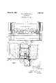
Other objects of our present invention will be ex lained in the following description and al features are illustrated in the accompanying drawings wherein similar reference numerals designate corresponding parts in the several figures and wherein- Figure 1 is a fragmentary sectional view of the bottom portion of a sluice gate and sluice-way frame taken on line 1--1 of Figure 2; and
Figure 2 is a fragmentary vertical sectional view of the bottom porton of a sluice gate and sluice-way frame taken on line 22 of Figure 1.
In the drawings, our invention is shown in association with a sluicesway 1 that is provided adjacent its entrance with a frame 2 having inclined seal strips 3 that are designed to form a seat for the similar strips 4 carried by the sluice most portion of the sluice-way frame 2 is gate 5. The lowerembedded in the masonry 6 and is provided with a seat bar 7 and a striking plate 8. Both the seat bar 7 and the striking plate 8 are flushv with the bottom 9 of the tunnel and the upstream portion of the tunnel bottom is in substantially the same plane as the downstream portion of the tunnel bottom, but the portion shown to the right of the sluice-way frame in Figure 2 could be at a lower level than the upstream portion, or the portion shown to the left of the frame in Figure 2, without affecting this invention since the principal object, as abovestated, is the elimination of the depression in the tunnel floor on the upstream side of the sluice-way frame. It will be noted, by reference to Figure 2, that this form of construction does away with all obstruction to free water flow over the bottom of the tunnel and thereby avoids the formationof eddy currents and the accumulation of dbris near the gate seat and the striking plate.
The sluice gate 5, on its opposite sides, is provided with endless chain anti-friction rollers 10 which operate between vertical guides 11 when the gate is elevated or allowed to descend. Inclined seal strips 4,
forming the side members of the seal rim, are secured to the downstream side of the gate and contact with the similar seal strips 3 of the sluice-way frame 2 when thegate is closed. The respective top seal strips of the gate and the sluice-way frame are of usualconstruction. The gate shown may be of the self-closing variety, that is capable of closing against the sluice-way frame without the application of compression forces to its top, and the respective seal strips of the sluice-way frame and gate are inclined from the vertical to make possible a tight seal therebetween without allowing the gate seal strips to slide over the sluice-way frame seal strips. sistance between the gate seal strips and the sluice way frame seal strips when the gate is being vertically elevated, because the gate seal strips leave their seat immediately upon application of the lifting force and do not slide over or upon the sluice way -frame seal strips to an extent which would make the elevation of the gate difiicult or impos sible without the application of excessively large lifting forces.
' a For the purpose of adjusting the extent of descent of the gate to ensure a watertight seal without encountering friction when elevating the gate, the set-screws 12 are provided. These set-screws abut against the striking plate 8 and are carried by'the beam 13. By suitably adjusting these setscrews, the lowermost position of the gate may be determined, a water-tight seal between the seal strips of the gate and the cor.- responding seal strips of the sluice-way frame eflected and the seal strips of the gate This feature avoids frictional re positioned in non-frictional relation to the seal strips of the sluice-way frame.
Since the overlapping and, consequently, self-adjusting gate and frame bottom seal referred to in connection with the Broome patent has been done away with by eliminating the offset in the tunnel floor, it. becomes necessary to provide a separately adjustable means for obtaining a water-tight seal between the bottoms of the gate and sluice-Way frame for all positions in which it may be necessary to set the gate to obtain a water-tight and nonfrictional relation between the side and top seal strips of the gate and the corresponding seal strips of the sluice-way frame. The means provided for this purpose comprises a seal bar 14 which is provided with a plurality of slotted holes 15. This seal bar 14 has its opposite ends fitted into cutaway portions 16 of the side seal strips 4 and may be adjusted up or down with relation to such side seal strips throu h holes in the flanges 18 of beam 13 I and t rough the slotted holes 15 are provided for securing the seal bar 14 in any adjusted position.
To further explain the important features of our invention, the adjustment of the gate with relation to the side seal strips of the sluice-way frame and the seat bar 7 will be briefly described. The'bolts 15 are loosened sufficiently to permit the seal bar 14 to slide freely, then the gate or, rather, the lowermost'position of the gate, is adjusted up or down by means of the set-screws 12 until the side and top seal strips of the gate are positioned in Water-tightand non-frictional relation to the corresponding seal strips of the sluice-Way frame, whereupon the set-screws 12 may be secured to maintain this position by means of the lock nuts 19. When this has been accom lished, the seal bar 14 may be lowered or p aced in water-tight relation to the seat bar 7, and fastened by means of the bolts 17 which have awater-tight relathe gate when lowered onto the frame seal bar 7.
From the preceding description, it will be obvious that our invention effectively eliminates both ofisets and the necessity for ofi sets in the tunnel floor, and makes for more positive and certain operation of the gate avoids the formation of eddy currents an increases the water flow efficiency of the sluice-way.
While our invention has been described with particular reference to the type of sluice gate shown in the Broome patent, yet it is-understood that it may be employed in other types of sluice gates and for other purposes without foregoing any of its advantageous features as set forth in the appended claims.
Having thus described our invention, what we claim is:
1. In a sluice gate, adjustable sealing means mounted upon the bottom of said gate, and other means on the gate for limiting the lowermost position of said gate.
2. In a sluice gate, adjustable sealing means mounted upon the bottom of said gate, and other adjustable means on the gate for limiting the lowermost position of said gate.
3. The combination of a sluice way and a sluice way frame having a striking plate and a seal bar so mounted therein as to be flush with the floor of said sluice way, the floor of the sluice way at the sluice way frame being substantially flat, and free of any offsets.
4. The combination of a sluice way and a sluice Way frame having a striking plate and seal bar so mounted therein as to be fiush with the floor of said sluice way, of a coacting sluice gate having a means for limiting the lowermost position of said gate relative to said frame adapted to rest upon said striking plate, and adjustable sealing means mounted upon the bottom of said gate adapted to contact with said seal bar, the floor of the sluice way being free of any offsets.
5. The combination of a sluice way and a sluice way frame having a striking plate and seal bar so mounted therein as to be flush with the floor of the said sluice way, of a coaeting sluice gate having a means for limiting the lowermost position of said gate relative to said frame adapted to rest upon said striking plate, and adjustable sealing means mounted upon the bottom of said gate adapted to contact with said seal bar, the floor of the sluice way on the up stream side of said sluice way frame being substantially flat, and free of any offsets.
6. The combination with a sluice way frame having an inclined seat and a sluice gate having a similarly inclined seat, said gate having means for limiting the lowermost position of said gate with relation to said frame and adjustable means mounted upon the bottom of said gate for forming a water tight seal between the bottom of said frame and said gate.
7. The combination of a sluice way and a sluice way frame having an inclined seat of av sluice gate having a similarly inclined seat vertically movable with respect to said frame, said gate having means for limiting the lowermost position of said gate with relation to said frame and adjustable means mounted upon the bottom of said gate for forming a water tight seal between the bot-,
tom of said frame and said gate.
8. In a sluice gate, adjustable sealing means mounted upon the bottom of said gate, and means independent of said sealing means for limiting the lower-most position of said gate.
In testimony whereof we hereby affix our signatures.
HARRY W. HOLMES. ERWIN B. PHILIPS.
Priority Applications (1)
| Application Number | Priority Date | Filing Date | Title |
|---|---|---|---|
| US104201A US1663406A (en) | 1926-04-23 | 1926-04-23 | Sluice gate |
Applications Claiming Priority (1)
| Application Number | Priority Date | Filing Date | Title |
|---|---|---|---|
| US104201A US1663406A (en) | 1926-04-23 | 1926-04-23 | Sluice gate |
Publications (1)
| Publication Number | Publication Date |
|---|---|
| US1663406A true US1663406A (en) | 1928-03-20 |
Family
ID=22299186
Family Applications (1)
| Application Number | Title | Priority Date | Filing Date |
|---|---|---|---|
| US104201A Expired - Lifetime US1663406A (en) | 1926-04-23 | 1926-04-23 | Sluice gate |
Country Status (1)
| Country | Link |
|---|---|
| US (1) | US1663406A (en) |
Cited By (2)
| Publication number | Priority date | Publication date | Assignee | Title |
|---|---|---|---|---|
| US4265564A (en) * | 1979-10-24 | 1981-05-05 | Rodney Hunt Company | Sluice gate assembly |
| US20160141055A1 (en) * | 2014-11-19 | 2016-05-19 | Mitsubishi Heavy Industries, Ltd. | Pit gate, pit equipment, nuclear power facility, and installation method of pit gate |
-
1926
- 1926-04-23 US US104201A patent/US1663406A/en not_active Expired - Lifetime
Cited By (3)
| Publication number | Priority date | Publication date | Assignee | Title |
|---|---|---|---|---|
| US4265564A (en) * | 1979-10-24 | 1981-05-05 | Rodney Hunt Company | Sluice gate assembly |
| US20160141055A1 (en) * | 2014-11-19 | 2016-05-19 | Mitsubishi Heavy Industries, Ltd. | Pit gate, pit equipment, nuclear power facility, and installation method of pit gate |
| US9697915B2 (en) * | 2014-11-19 | 2017-07-04 | Mitsubishi Heavy Industries, Ltd. | Pit gate, pit equipment, nuclear power facility, and installation method of pit gate |
Similar Documents
| Publication | Publication Date | Title |
|---|---|---|
| US1663406A (en) | Sluice gate | |
| KR101183935B1 (en) | Rotary type floodgate | |
| KR20130107816A (en) | Pump gate | |
| KR102021973B1 (en) | Hydrological structure that can prevent accumulation of foreign matter | |
| KR101129042B1 (en) | Water gate structure | |
| US3331158A (en) | Automatic door seal | |
| US1938675A (en) | Crest gate | |
| US2643521A (en) | Sluice gate seal | |
| KR101926810B1 (en) | Ascent-Type HDPE Sluice | |
| JP2614177B2 (en) | Lockhouse type fishway equipment for dams | |
| KR200355906Y1 (en) | Construction of Floodgate | |
| KR100994564B1 (en) | roller gate and installing method thereof | |
| US2479449A (en) | Automatic dump skip | |
| CN212103951U (en) | Water conservancy blocks sand water intaking gate | |
| KR101934407B1 (en) | Conducting movable beam of low water layer discharge structure | |
| KR100684364B1 (en) | Shutter floodgate | |
| KR102040859B1 (en) | A Roller Contacting Typer of a Water Gate Apparatus | |
| US1644814A (en) | Double-hung window | |
| KR200325075Y1 (en) | Door guiding structure of floodgate | |
| KR101285341B1 (en) | Hydraulic movable weir with boundary of fresh water and salt water | |
| KR101121743B1 (en) | A floodgate | |
| KR101924203B1 (en) | Floodgate structure for preventive sediment | |
| US1404048A (en) | Window construction | |
| US1995431A (en) | Sealing strip for roll top doors | |
| KR100640150B1 (en) | A cover of vanishing type gate for weir and dam |