US1663403A - Drilling machine - Google Patents
Drilling machine Download PDFInfo
- Publication number
- US1663403A US1663403A US360619A US36061920A US1663403A US 1663403 A US1663403 A US 1663403A US 360619 A US360619 A US 360619A US 36061920 A US36061920 A US 36061920A US 1663403 A US1663403 A US 1663403A
- Authority
- US
- United States
- Prior art keywords
- valve
- piston
- cylinder
- fluid
- passage
- Prior art date
- Legal status (The legal status is an assumption and is not a legal conclusion. Google has not performed a legal analysis and makes no representation as to the accuracy of the status listed.)
- Expired - Lifetime
Links
Images
Classifications
-
- E—FIXED CONSTRUCTIONS
- E21—EARTH DRILLING; MINING
- E21B—EARTH DRILLING, e.g. DEEP DRILLING; OBTAINING OIL, GAS, WATER, SOLUBLE OR MELTABLE MATERIALS OR A SLURRY OF MINERALS FROM WELLS
- E21B6/00—Drives for drilling with combined rotary and percussive action
Definitions
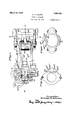
- My invention relates generally to drilling machines and particularly, but not exclusively, to those fordrilling rock and like formations and in this respect comprehends among 7 chine embodying my invention;
- Fig. 2 shows a. section on the line2-2 of Fi 1'
- Fig. 3 shows an end elevation of Fig. 1
- Fig. 4 shows a section on the line 4-4 of Fig. 2 with thepiston omitted;
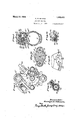
- Figs. 5 and 6 respectively show sections on the lines 55 and 66 of Fig. 1;
- Figs. 7 8 and 9 respectively show sections .through the throttle valve on the lines 77,
- Fig. 10 shows a section on the line 10-10 of Fig. 3;
- Fig. 11 shows a section on the line 1111 of Fig. 3; 1 P
- Fig. 12 is adevelopment of the exterior surface of the throttle valve
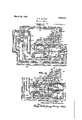
- Figs. 13 and 14 represent dia rammatically the arrangementof ports an passages in the submitted embodiment of my invention, Fig. 13 showing the piston at the front end of the cylinder and Fig-14 showing the piston at the rear end of the cylinder; and
- Fig. 15 is a section on the line 15-15 of Fig. 2.
- the embodiment of my inventlon herein submitted comprises a cylinder member 1 in which is mounted a piston having a head portion 2 and a projectingstem or hammer bar 3.
- This piston is .mounted for reciprocation
- the front end of the cylinder is closed by a front head 4 provided with an extension 5 for receiving the hammer bar.
- a drill steel 6 mounted in frontof the hammer bar in position to be struck thereby is a drill steel 6, said drill steel being carried by a chuck which may be rotated by an independent rotation motor comprising the rotor-.7 carried by the extension 5.
- the chuck and independent rotation motor just referred to may be of any suitable type, as for example that shown in United States Letters Patent No.
- the .rear end of the cylinder is closed by a rear cylinderhead 8 which has integrally formed therewith a distributing plug 9 having a head portion 10.which fits the reduced interior bore 11 of the chamber 12 formed in the piston/
- the plug as shown is provided with a passage 12 for conveying motive fluid to the internal piston chamber, the flllld. being discharged from the passage 12 through laterally directed passages 13 which may be controlled by means of the reduced bore 11.
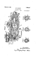
- the piston illustrated is provided adjacent the front end of the internal chamber with passa es 14 for conveying fluid from said cham er to the distributingpassage 15 which herein takes the form of an annular groove formed on the exterior wall of the piston, this groove and the groove 16 formed in the interior wall of the cylinder being adapted to convey fluid from the internal chamber to the front end of the cylinder when the pistonis near the forward end of its stroke.
- the distributin assage 15 communicates with a passage 1% eading from the intermediate to the rearward end of the cylinder in order that fluid may be conducted from the interior piston chamber to the rearward end of the c linder.
- the distributing plug is shown as formed with a tapered annular groove, as indicated in Fig. 2 at 9'.
- This groove serves to increase the volume of the rear cylinder chamber and also serves when the rearward edge of the head passes into the internal piston chamber on the rearward stroke of the, piston to admit fluid from said internal chamber to the rearward portion of the cylinder.
- This event preferably is caused to occur before the distributing groove 15' is brought into communication with the passage 17 in order to admit a small volume of air to the rear of the cylinder to cushion the same.
- the point at which this cushioningefiuid is admitted may be. regulated by suitably proportioning. the length of the groove 9 or by substituting diflerent distributing plugs for different conditions of work, the said different distributing plugs having grooves of different length.
- cushioning fluid may be admitted through the passage 17 and the main supply of air through the groove 9, which may be done bysuitably locating them with relation to the part of the piston which uncovers them to admit fluid by way of them to the rear of the cylinder.
- the passages 13 are so located that they are partially closed when the piston-is at the end of its forward stroke. This will reduce the flow to the internal piston chamber by throttling action and thereby reduce the pressure of the fluid transferred from the internal chamber to the front end of the cylinder, In order that the piston may strike a powerful. blow it is desirable that no more pressure should exist in front of the piston at anytime than is necessary to distribute the fluid to cause the piston to 0pcrate and only enough air need be admitted to the front end of the cylinder as is necessary to return the piston without doing any other work.
- the passages for supplying the front end of the cylinder must open before the piston reaches the end of its forward stroke but by throttling the flow-before or at the time air is transferred from the internal chamber to the front of the piston, the air admitted to the front end of the cylinder is at reduced pressure and in consep11ence thereof, does not unnecessarily check t e blow of the piston.
- the return stroke is initiated as a result of the difference in the total pressures exerted by the motive fluid on the larger front face, of the piston and the relatively smaller internal effective area of the piston.
- the ports 13 and 14 preferably are so located with relation to each other and to the distributing passage -15 and groove 16 that an additional amount of air will be admitted to the front of the cylinder as the piston starts to return and as this will occur after the blow has been struck no harmful efi'ect'will result.
- I provide a port 17' for establishing communication between the interior of the cylinder and the atmosphere when the piston is adjacent the forward end of its stroke for exhausting the rear end of the cylinder.
- the hammer bar 3 pulls out of the chamber for reciving it in the front head, the air in the front end of the cylinder under these conditions exhausting through the passage 24 to the atmosphere in a manner which will hereinafter be more fully set forth.
- ports 13 may be closed and the pist on may not start to operate when the motive fluid supply is reestablished.
- one or more ports 13 of restricted area are formed through the front end of the plug.
- these ports may be 1 mad'eso small that they play no part in the operation of the machine during the normal running conditions but under the conditions just mentioned they will admit sufficient air to the internal ,plston chamber slowly to move the piston rearwardly to' uncover the ports 13 and initiate the normal running conditions.
- the drill steel 6 it is to be noted that the drill steel 6.
- a portion of the air which exhausts from the front end of the cylinder when the hammer bar withdraws, will find its way into the bore 17 a and be discharged into the drill hole and will cleanse the same of dbris.
- this valve in the form of a double spool valve mounted on the upper portion of the cylinder.
- I may rovide the cylinder with the boss 29 provided with a transverse bore in which is inserted from opposite ends, the bushings 30 and 31.
- Closing the ends of the 'bore are shown heads 32 and 33, respectively provided with inwardly projecting cylindrical stems 34 and 35, these stems fitting corresponding recesses in the end of the'valve and one stem being of larger diameter than the other.
- the heads and valveare suitably apertured to receive a bolt 36.
- the portion of the central aperture of the valve between the end recesses is vented'to the atmosphere toeliminate the transfer of pressure through the aperture from one recess to the other.
- This aperture ma be in the form of ahole 37 drilled-throng the bolt and communicating with the. aperture by means of a port 38.
- the space 39' about the central reduced portion of the valve 28 is in constant communication with the atmosphere through a passage 40, and the bushings 30' and 31 respectively are provided with grooves 41. and 42 which are adapted alternately to be alternately placed-in communication with this space.
- the bushings 30' and 31 are provided with grooves 41. and 42 which are adapted alternately to be alternately placed-in communication with this space.
- groove 41 isshown a passage 26, and from the rearward end of the cylinder to the groove 42 a passage 25.
- the rear end of the cylinder will be put in communication with the atmosphere by means of.the passage 25, groove 42 and passage 40, and when the-valve isat the right hand end of its travel the pa-ssage26 will be placed in communication with the atmosphere through a similar arrangement of ports, it being understood, of course, that when one port is opened, the other is closed and that when desired one port maybe omitted in order that the valve may control but one end of the cylinder.
- Suitable. means for biasing the valve to move in one direction is preferably employed and for this purpose the smaller end of the valve may be subjected constant- 1 to the'pressure of the motive fluid supply. 0 cause the valve to move, the opposite end thereof may be intermittently connected t0 the source of fluid pressure and to the atmosphere.
- Rearwardlypf the port 19*in this embodiment is formed a passage 44 extending through the cylinder Wall.
- the port 19 is put in communication with the atmosphere by means of a groove 45 formed in the exterior surface of the piston adjacent its rearward end.
- the interior piston chamber is placed into communication with the ports 19 and 23, thus supplying fluid to the larger end recess of the valve which forces it to such position as to close the passage 25 leading to the rear end and open the passage 26 leading to the front end of the cylinder.
- the port 19 isin communication with the atmosphere, the air which has been admitted to the larger recess of the valve is, exhausted to the atmosphere and the constant pressure on the smaller recess of the valve moves
- the valve 28 is mounted to move transversely to the direction of percussion in. order that its'motion will be ugiafiected by vibration.
- valve 17 through which motive fluid is admitted from the fluid inlet connection 48 to a passage 22,
- valve 47 hereinbefore referred to is shown in the submitted embodiment of my invention in the form of a hollow tapered plug v'alve provided with a suitable handle 49 for manipulating the same.
- a port 51 leading from the internalchamber 5 0 of the valve is a port 51 in the form of a groove of such dimensions respective to the permitted throw of the valve that no matter what the position of the valve, air. is constantly supplied to theport 22 communicating therewith, this being clearly shown by Fig. 8.
- I may provide a second port 52'exte-nding through the wall of the valve, and in the same plane therewith, a groove 53 on the exterior surface of the valve, as is clearly shown in Fig. 9.
- Communicating with the groove 53 in the position shown by Fig. 9 is a forwardly directed groove 54 in the valve casing leading to the atmosphere.
- valve 47 leads a passa e 27 to the chamber 55 in the rear head bloc k, the passage 27 being utilized to conve air to the chamber 55 and hence to the cylinder by means of the distributing plu when the valve is in the position shown by .ig. 9.
- Fig. 9 represents the valve in-the normal running position of the machine.
- the valve may be turned from this position to such a position that the port 52 thereof is placed in communication with'the passage 24, nor
- a non-positive stop which may be inthe form of a spring pressed ball 56 adapted to engage suitable spherical recess 57, formed on the exterior surface of the ya-lve, as is shown by Fig. 7.
- a non-positive stop which may be inthe form of a spring pressed ball 56 adapted to engage suitable spherical recess 57, formed on the exterior surface of the ya-lve, as is shown by Fig. 7.
- the valve In the position shown by Fig. 7, the valve is in full running position.
- passage 52" of the valve is between the passages 24 and 27 and the supply to the cylinder is interrupted. Further clockwise movement will place the upper recess 57 into engagement with the ball and in this position the passage 52 will be placed in communication with the passage 24 and the hole will be blown.
- the valve casing is provided with stops 57 for engaging the valve handle and determining the limits of the throw of the valve. The angular position of these stops corresponds to the positions of the two end rece
- the passage 22 hereinbefore referred to may lead to a valve 58 of any suitable construction for controlling the motive fluid supply to the chuck rotating motor.
- the valve is shown as a plug valve provided with a handle 59 for manipulating the same, the valve 58 being provided with a suitable transverse passage. 60 which is adapted to establish communication between the passage 22 and a passage 22 the latter communicating with the intakes of the chuck rotating motor.
- the passage 22 herein extends through the rear head block and communicates with a passage 22 formed in the wall of the cylinder and front cylinder head, the latter communicating with a passage 22 which is formed in the spacing ring 61, and communicates with the two inlet ports 7 of the chuck rotating motor between the cylinder head and the motor casing 62. From the foregoing it will be obvious that the chuck rotating motor may be rendered operative or inoperative at the will of the operator by opening or closing the valve 58.
- a suitable tube 63 which extends from a chamber 64 in the rear head I 1,ees,4os
- the rear end of the chamber beoperates as follows ing closed by means of a screw threaded plug 69 and between the inner end of the plug and the flange of the tube is placed a washer 7 0 provided with suitable radial passages 71 for leading water from the chamber to the tube.
- Any suitable'means may be provided for supplying the water to the chamber and in the embodiment shown this is done by providing a passage extendingthrough the rear head block from the water intake connection 66 to the chamber.
- the handle portion of the valve may be provided with a cupped member 72 having suitable recess 73 for engaging a plunger 74 of a yieldable non-positive stop.
- the member 72 also may be provided with stop members 75 ada ted ,to engage an abutment 76 at the ends 0 the throw of the valve.
- the machine I may provide my rear head block with. an oil reservoir which is provided with afilling orifice 78 closed by the plug 79, .Fromthe oil chamber to the motor I. may convey oil. in any suitable manner and as shown I pro-v vide the interior portion of the oil chamber with a boss 80, as is clearly shown in Figs. 3 and 10.
- the boss is providedwith a central longitudinal bore .81 and leading therefrom to the motive fluidcham'ber 55 are a pair of spaced passages 82 and 83, and communicating with the bore intermediate the passages 82 and 83 are formed passages 84 and 85 leading-tothe oil chamber.
- a valve-like member comprising the heads 86 and 87 and an intermediate reduced portion 88.
- the valve is biased to move'by the spring 89 in such a direction as to put the space of the valve between the heads 86 and 87 in communication with the passages 84 and 85 leading to the oil chamber.
- the spring 89 just referred to may be carried by a plug9'0 closing the end of the bore shown in communication with that in which the valve-like member is mounted. To drain of! any oil which. may
- valve having a longitudinal passage opening on the large end of said valve, a
- valve casing a passage connecting said valve casing s, means placing said last named passage vin constant communication with said longitudinal passage of said valve comprising a cooperatin port and recesses in said valve and its a ve casing at that side of said port of said valve which is opposite the large end of said valve, and a valve in said second mentioned valve casing for controlling the motive fluid supply to said motor.
- a tool In a drilling machine, a tool, a motor for rotating said tool, a motor "for hammering said tool, a source of motive fluid supply for said motors, conduit 'means for conucting motive fluid from said motor forcation with the motor for rotating said tool d duit means to said source.
- a tool in a drilling machine, a tool, a tool rotating motor and a percussive motor for actuating said tool, an exhaust conduit for said percussive motor having a connection for supplying fluid to the work and a separate connection to the atmosphere, means for conducting 'motive fluid to said motors for their actuation, and means for interrupting said connection of said conduit to the atmosphere without interrupting the supply for the actuation of said tool rotating motor and for simultaneously supplying live fluid to said conduit.
- a tool In a drilling machine, a tool, a tool rotating motor an'd'a percussive motor for actuatingsaid tool, an exhaust conduit for said percussive motor having a connection for supplying-fluid to-the work and a separate connect-1on to the atmosphere, means for conducting motive fluid to said motors for their actuation, and means for interrupt ing said connection of said conduit to the' atmosphere without terrupting the supply for said tool rotating motor.
- a 'drillin machine having, in combination, a chuck or a-hollow drill steel, conduit means independent of the bore of said hollow drill steel for placing said chuck in com-' munication with the atmosphere, a percussive motor, a chuck rotating motor, means for conducting motive fluid from a motive fluid supply connection to sai motors for their a ctuation, and valve mean for at will diverting the supply of motive fluid for said percussive motor to said conduit means for supplying fluid to the' work and a sep- I arate connection to the atmosphere, means for conducting motive fluid to said motors for their actuation, and coordinated valvular means for interrupting said connection of said conduit to the atmosphere without interrupting the supply for the actuation of said tool rotating motor and for simul taneously supplying live fluid to said conuit.
- a chuck adapted to carry a hollow drill steel with the bore of said steel in communication with said chuck, a percussive motor, a chuck rotating motor, means 'for conducting motive fluid to said motors for their actuation, an exhaust passage for said percussive motor, and coordinated valvular means whereby said exhaust. passage may be blanked without interrupting the supply to said chuck rotating motor and live motive'fluid may be simultaneously supplied directly to said chuck.
- a chuck adapted to carry a. hollow drill steel with the bore of said steel in communication with said chuck, conduit means independent of the bore of said steel for placing said chuck in communication with the atmosphere, a chuck rotating motor and a percussive motor,
- a hammer. piston having an extension, an exhaust passage controlled by said extension, conduit means connecting said passage to the work, a tool rotating motor, and coordinated valvular means providing a conduit for the fluid aetuating said piston and motor and for, supplying live fluid to said exhaust passage without interrupting the flow of fluid for actuating said motor.
- conduit means including a passage communicating with said cylinder. and controlledby said piston for admitting fluid to the work when the piston rupting the-actuation of said piston without v that of said motor and simultaneously supplying motive fluid directly to said passage.
- a chuck adapted to carry a hollow drill-steel with the bore of said steel in communication with said chuck, a percussive motor having an exhaust out-let, a breather passage separate from said hollow drill steel connecting said chuck to the atmosphere, and means for interrupting the actuation of said motor and simultaneously supplying motive fluid to said pas- 15.
- a chuck rotating motor for "hammering said tool: a chuck adapted cluding a valve for supplying said motors with actuating fluid, and ports for said valve whereby said passages may be supplied with live motive fluid without interrupting the actuation of said motor for rotating said tool.
- a valveless fluid operated percussive motor for the drilling tool for the drilling tool, a fluid motor for rotating the drilling tool, a chuck for thedrilling tool, a passage for directly connecting said'chuck to the atmosphere, a valve for-conducting actuatmg fluid to sald motors, said valve in one position thereof diverting the supply for said percussive motor to-said passage and interrupting the connection of said passage with the atmosphere and without interruptingthe supply of actuating fluid-to said;
- a valveless V fluid operated percussive motor for the drilla ing tool, a chuck, apressure fluidactuated motor for rotating said chuck, a valve affording a conduit open in all positionsof said valve for supplying said motor for rotating the chuck with actuating pressure fluid, and a passage controlled by said valve for optionally connecting said chuck to the atmosphere or for supplying it with live pressure fluid.
- a drilling machine having, in combination, a cylinder, a hammer piston therein,- a chuck for carrying a hollow drill steel, means for admitting motive fluid to the front end of said cylinder for-actuating said piston, means for exhausting such motive fluid including a fluid actuated valve and a passage controlled thereby, said'valve normally biased toward a position in which said passage is closed, said piston having, a hammer bar for impacting the drill steel and for establishing communication between the front end .ofsaid cylinder and said chuck when said piston is moved rearward by m0- tive fluid admitted.
- valve for exhausting such motive .fluid including a fluid actuated valve and a passage controlled thereby, said valve having piston, means a working pressure surface, conduit means for supplying motive fluid for acting upon said surface whereby said valve is normally biased toward a position in which said pas ⁇ sage is closed, said pistonhaving a hammer bar for impacting the drill steel and for establishing communication between the front end of said cylinder and said chuck when said piston is moved rearward by'motive fluid admitted to said end, and means.
- a percussive motor an exhaust discharge means for said motor. avvalve-controlling said meanstmeans normally holding said valve in position to close said exhaust dlscharge, means for causing said valve to open intermittently in consequence of movement of said motor.
- conduit means for conducting cleansing fluid to the work having communication with said ex haust discharge means, and means for interrupting movement of saidmotor and for supplying cleansing fluid to said conduit.
- a'percussive motor an auxiliary exhaust passage for an expansible chamber of said'motor, an automatically acting controlling valve for said exhaust passage, valve means independent of said controlling valve foradmitting cleansing fluid to said chamber, means conducting such fluid from said chamber to thework, and means for causing said valve to close said exhaust passage when said cleansing fluid is admitted to said chamber.
- a valveless admission and a main and auxiliary exhaust means for an expansible chamber of said motor an automatically acting controlling valve for said auxiliary exhaust means, means admitting cleansing fluid to said chamber, and means for causing said valve to close said auxiliary exhaust'means when said cleansing fluid is admitted.
- amain and an auxiliary exhaust means for an expansiblc chamber of said motor, an automatically acting controlling valve for said auxiliary exhaust means, fluid means for causing said valve to close said auxiliary exhaust means irrespective of the pressure condition of said chamber, means responsive to motion of said motor for periodically causing said valve to open said exhaust, conduit means having communication with said chamber for conducting cleansing fluid to the work, and means for interrupting motion of said motor and for admitting cleansing fluidto said conduit means.
- a piston having a head and hammer bar, a cylinder having chambers for said head and hammer bar, said hammer bar when said piston is in its rearward position establishing communication between said chambers, means for admitting live motive fluid to the chamber, for said bar and conducting it to the work, an exhaust means for the chamberfor said head, and means for closing said exhaust means when said chamber for said head is supplied with said cleansing fluid whereby escape of such. fluid by way of said exhaust is prevented.
- a percussive motor having, in combination, a cylinder, a hammer piston in said cylinder, said piston having an internal chamber the forward end. of which forms a forwardly acting pressure face for said piston. a tube carried by said cylinder projecting into. said chamber for supplying motive fluid thereto. cooperating ports and passages formed in said piston and cylinder for estabfishing-communication between said internal chamber and'the forward end of said cylindcr during the latter part of the forward stroke ofsaid piston.
- motive fluid conducting means formed in said tube for establishing con'ununication between the interior'a'nd exterior of said tube at its forward portion, said means including a laterally'opening port controlled by said piston for establishing communication between the interior of said 2 tube and said internal chamber when the piston is at the rearward portion of its stroke.
- a percussive motor having, in combination, a cylinder, a hammer piston in said cylinder, said piston having an internal chamber the forward end of which forms a forwardly acting pressure face for said pisfton, a tube carried by said cylinder projecting into said chamber for supplying motive fluid thereto, cooperating ports and passages formed in said piston and cylinder for establishing communication between said internal I port controlled by said piston for establishmg communication bet-ween the interior ,of said tube and said internal chamber when the piston is at the rearward portion of its stroke and restricting such communication when said piston during its forward stroke establishes communication between the forward end of said cylinder and said internal chamber.
- a percussive motor having, in combination, a cylinder, a hammer piston in said cylinder, said piston having an internal chamber the forward end of which forms a forwardly acting pressure face for said piston, a.tube' carried by said cylinder projecting into said chamber for supplying motive fluid thereto, cooperating ports and passages formed in said piston and cylinder for establishing communication between said internal chamber and the forward end of said cylinder during the latter part of the forward stroke ofsaid piston, motive fluid conducting means formed in said tube for establishing communication between the interior and exterior of said tube at its forward portion,
- said means including a laterally opening port controlled by said piston for establishing communication between the interior of said tube and said internal chamber when the piston is at the rearward portion of its stroke and interrupting such communication when said piston is in its extreme forward position relative to said cylinder.
- a percussive motor having, in combination, a cylinder, a hammer piston therein, said motor comprising means forming two expansible chambers respectively including a forwardly acting pressure surface and a rearwardly acting pressure surface on said piston, means for supplying motive fluid to the expansible chamber which includes said forwardly acting surface for driving the v piston forward and from said chamber to the other expansible chamber for driving the piston rearward, said means including a port T a controlled directly by said piston for establishing commumcation between said.
- a percussive motor having, incombination, a cylinder, a hammer piston therein, said motor comprising means forming two expansible chambers respectively including a forwardly acting pressure surface and a rearwardly acting pressure surface on said piston, means for supplying motive fluid to the expansible chamber which includes saidforwardly acting surface for driving the piston forward and from said chamber to the other expansible chamber for driving the piston rearward, said means including a port controlled directly by said piston for establishing communication between said cham bers when said piston is at the forward portion of its stroke, and a motive fluid conducting means controlled by said piston for establishing communication between a source of motive fluid supply and that chamber which includes said forwardly acting surface,said motive fluid conducting means being closed by said piston when the latter is in its extreme forward position relative to said cylinder.
- a motor a cylinder, a piston therein having an internal chamber, means for admitting and exhausting motive fluid to and from said cylinderfor actuation of said piston, said means including a valve, and means for connecting said internal chamber to said valve for actuation thereof in one position of the Piston.
- a motor a cylinder, a piston therein having a distributing conduit, means for admitting and xhausting "motive fluid to and from said cy inder for actuation of said piston, said means including a valve, and means for connecting said conduit to said valve for actuation thereof and to a cylinder end during the reciprocation of said piston.
- a cylinder, a piston therein I having a distributing conduit, means for admitting and exhausting motive fluid to and from said cylinder for'actuation of said pis-' ton, said means including a valve, and means for connecting said conduit to said valve for actuation thereof and to opposite cylinder ends during the reciprocation of-said iston.
- a motor In a motor, a cylinder, a piston t erein havin of which forms a forwardly acting ressure surface for said piston, a motive flui supply conduit communicating with said chamber, means for admitting and exhausting motive fluid to and from said cylinder for actuation and passage means controlled by said piston for connecting said conduit to said valve for actuation thereof and to opposite cylinder ends, during the reciprocation of said'piston.
- a percussive motor a cylinder, a piston, admission means controlled solely and directly by said piston, exhaust means di-- rectly controlled by said piston, an auxiliary exhaust valve, a conduit passing through said piston for controlling said valve, said conduit having a lateral port, and a passage in said cylinder having a lateral port positioned to communicate intermittently with said first named port for actuation of said valve.
- a cylinder In a motor, a cylinder," a piston therein an internal chamber the forward end of said piston, said means including a valve,
- conduit means adapted to establish communication between sa d interior and exterior chambers, .one of said conduit means including a passage formed by the cylinder wall, and means for progressively putting said conduit means in communication with said interior chamber for first conducting cushioning fluid to the end of the cylinder by one conduit means and then conducting additional fluid thereto by another conduit means.
Description
March 20, 1928;
G. H. GILMAN DRILLING MACHINE Filed Feb. 24. 1920 4 Sheets-Sfietl ZEKMWJWQ$ Invenior: gait Gilmn,
March 20, 1928.
G. H. GILMAN DRILLING MACHINE '4 Sheets-Sheet 5 Filed Feb. 24, 1920 Inventor.- v ar-391217. Gilman, by
Patented, Mar. 20, 1928.
umrau STAT-ES- GEORGE E. GILm, OF BOSTON, MASSACHUSETTS.
' DBILLING mom.
Application filed February 24, 1920. Serial No. 880,818
My invention relates generally to drilling machines and particularly, but not exclusively, to those fordrilling rock and like formations and in this respect comprehends among 7 chine embodying my invention;
Fig. 2 shows a. section on the line2-2 of Fi 1' Fig. 3 shows an end elevation of Fig. 1; Fig. 4 shows a section on the line 4-4 of Fig. 2 with thepiston omitted;
. Figs. 5 and 6 respectively show sections on the lines 55 and 66 of Fig. 1;
Figs. 7 8 and 9 respectively show sections .through the throttle valve on the lines 77,
88 and 9-9 of Fig. 2;
Fig. 10 shows a section on the line 10-10 of Fig. 3;
Fig. 11 shows a section on the line 1111 of Fig. 3; 1 P
Fig. 12 is adevelopment of the exterior surface of the throttle valve;
Figs. 13 and 14 represent dia rammatically the arrangementof ports an passages in the submitted embodiment of my invention, Fig. 13 showing the piston at the front end of the cylinder and Fig-14 showing the piston at the rear end of the cylinder; and
Fig. 15 is a section on the line 15-15 of Fig. 2.
Referring particularly to Fig. 2, the embodiment of my inventlon herein submitted comprises a cylinder member 1 in which is mounted a piston having a head portion 2 and a projectingstem or hammer bar 3.
This piston is .mounted for reciprocation,
' and in the embodiment of my invention submitted is what is termed in the art a floating piston, that is, one which 1s not restrained in respect to its angular motion to follow a fixed path, as would be the case if,
for example, it were splinedto the cylinder by means of grooves or similar cam structures.
The front end of the cylinder is closed by a front head 4 provided with an extension 5 for receiving the hammer bar. Mounted in frontof the hammer bar in position to be struck thereby is a drill steel 6, said drill steel being carried by a chuck which may be rotated by an independent rotation motor comprising the rotor-.7 carried by the extension 5. The chuck and independent rotation motor just referred to may be of any suitable type, as for example that shown in United States Letters Patent No. 1,605,712, granted to me November 2, 1926, wherein the rotor 7 is in the form" of a ring gear (F1 15) journalled on the extension 5 and mes ing with the gears 7, the latter servin as rotary abutments for the elon 'ated teeth or pistons 7 of the rotor 7. erein the rotor is provided with the inlet ports 7 adapted to be supplied with motive fluid,-
as hereinafter described,'and with exhaust ports 7 leading to the atmosphere.
Herein the .rear end of the cylinder is closed by a rear cylinderhead 8 which has integrally formed therewith a distributing plug 9 having a head portion 10.which fits the reduced interior bore 11 of the chamber 12 formed in the piston/ The plug as shown is provided with a passage 12 for conveying motive fluid to the internal piston chamber, the flllld. being discharged from the passage 12 through laterally directed passages 13 which may be controlled by means of the reduced bore 11.
The piston illustrated is provided adjacent the front end of the internal chamber with passa es 14 for conveying fluid from said cham er to the distributingpassage 15 which herein takes the form of an annular groove formed on the exterior wall of the piston, this groove and the groove 16 formed in the interior wall of the cylinder being adapted to convey fluid from the internal chamber to the front end of the cylinder when the pistonis near the forward end of its stroke. Herein, when the piston is adjacent the rear end of stroke, as shown diagrammatically by-Fig. 14, the distributin assage 15 communicates with a passage 1% eading from the intermediate to the rearward end of the cylinder in order that fluid may be conducted from the interior piston chamber to the rearward end of the c linder.
Rearwardly of the head 10 the distributing plug is shown as formed with a tapered annular groove, as indicated in Fig. 2 at 9'.
This groove serves to increase the volume of the rear cylinder chamber and also serves when the rearward edge of the head passes into the internal piston chamber on the rearward stroke of the, piston to admit fluid from said internal chamber to the rearward portion of the cylinder. This event preferably is caused to occur before the distributing groove 15' is brought into communication with the passage 17 in order to admit a small volume of air to the rear of the cylinder to cushion the same. The point at which this cushioningefiuid is admitted may be. regulated by suitably proportioning. the length of the groove 9 or by substituting diflerent distributing plugs for different conditions of work, the said different distributing plugs having grooves of different length.
This fluid of course, is available for operating the piston on the forward stroke. Obviously, the cushioning fluid may be admitted through the passage 17 and the main supply of air through the groove 9, which may be done bysuitably locating them with relation to the part of the piston which uncovers them to admit fluid by way of them to the rear of the cylinder.
Preferably the passages 13 are so located that they are partially closed when the piston-is at the end of its forward stroke. This will reduce the flow to the internal piston chamber by throttling action and thereby reduce the pressure of the fluid transferred from the internal chamber to the front end of the cylinder, In order that the piston may strike a powerful. blow it is desirable that no more pressure should exist in front of the piston at anytime than is necessary to distribute the fluid to cause the piston to 0pcrate and only enough air need be admitted to the front end of the cylinder as is necessary to return the piston without doing any other work. Obviously the passages for supplying the front end of the cylinder must open before the piston reaches the end of its forward stroke but by throttling the flow-before or at the time air is transferred from the internal chamber to the front of the piston, the air admitted to the front end of the cylinder is at reduced pressure and in consep11ence thereof, does not unnecessarily check t e blow of the piston. The return stroke is initiated as a result of the difference in the total pressures exerted by the motive fluid on the larger front face, of the piston and the relatively smaller internal effective area of the piston. In order to increase the volume of the forward piston chamber of the cylinder, and thereby to provide means to aid in reducing the pressure of the fluid admitted thereto and to maintain the pressure of the fluid after it is admitted I preferably provide suitable. reservoir chambers in communication with said piston chamber, these chambers,-in the submitted embodiment, taking the form of a plurality of holes.16
drilled in the cylinder Wall and intersecting the groove 16. The ports 13 and 14 preferably are so located with relation to each other and to the distributing passage -15 and groove 16 that an additional amount of air will be admitted to the front of the cylinder as the piston starts to return and as this will occur after the blow has been struck no harmful efi'ect'will result.
Preferably, I provide a port 17' for establishing communication between the interior of the cylinder and the atmosphere when the piston is adjacent the forward end of its stroke for exhausting the rear end of the cylinder. In the embodiment of my invention illustrated, during the rearward stroke of the piston the hammer bar 3 pulls out of the chamber for reciving it in the front head, the air in the front end of the cylinder under these conditions exhausting through the passage 24 to the atmosphere in a manner which will hereinafter be more fully set forth.
It may-happen in certain embodiments of my invention that when themotive fluid supply is cut off the piston may come to rest at the forward end of the cylinder, in which case the ports 13 may be closed and the pist on may not start to operate when the motive fluid supply is reestablished. To obviate this, one or more ports 13 of restricted area are formed through the front end of the plug. Preferably, these ports may be 1 mad'eso small that they play no part in the operation of the machine during the normal running conditions but under the conditions just mentioned they will admit sufficient air to the internal ,plston chamber slowly to move the piston rearwardly to' uncover the ports 13 and initiate the normal running conditions. In this connect-ion it is to be noted that the drill steel 6. may be provided with a bore 17 leadin to the cutting end andcommunicating at 51c rear end with the chamber in the front head for receiving the hammer bar. With this construction, a portion of the air which exhausts from the front end of the cylinder when the hammer bar withdraws, will find its way into the bore 17 a and be discharged into the drill hole and will cleanse the same of dbris.
It will be noticed that as the hammer bar recipr'ocates in the chamber of the front head it tends, by its alternate expansion and contraction of said chamber when it.
this valve in the form of a double spool valve mounted on the upper portion of the cylinder. Preferably I may rovide the cylinder with the boss 29 provided with a transverse bore in which is inserted from opposite ends, the bushings 30 and 31. Closing the ends of the 'bore are shown heads 32 and 33, respectively provided with inwardly projecting cylindrical stems 34 and 35, these stems fitting corresponding recesses in the end of the'valve and one stem being of larger diameter than the other. To hold the parts in assembled relation the heads and valveare suitably apertured to receive a bolt 36. Preferably the portion of the central aperture of the valve between the end recesses is vented'to the atmosphere toeliminate the transfer of pressure through the aperture from one recess to the other. This aperture ma be in the form of ahole 37 drilled-throng the bolt and communicating with the. aperture by means of a port 38. v
Herein, the space 39' about the central reduced portion of the valve 28 is in constant communication with the atmosphere through a passage 40, and the bushings 30' and 31 respectively are provided with grooves 41. and 42 which are adapted alternately to be alternately placed-in communication with this space. Leading from the forward end of the cylinder to, the
Suitable. means for biasing the valve to move in one direction is preferably employed and for this purpose the smaller end of the valve may be subjected constant- 1 to the'pressure of the motive fluid supply. 0 cause the valve to move, the opposite end thereof may be intermittently connected t0 the source of fluid pressure and to the atmosphere. Leading from the right hand ing with the port- 21 bored through thecylinder wall and comn'iunicating with the ,interior of the cylinder by means "0 f ports 19 and 23. Rearwardlypf the port 19*in this embodiment is formed a passage 44 extending through the cylinder Wall. and so located that when the piston is at the forward portion of its travel the port 19 is put in communication with the atmosphere by means of a groove 45 formed in the exterior surface of the piston adjacent its rearward end. When the piston is in the rearward'portion of its travel the interior piston chamber is placed into communication with the ports 19 and 23, thus supplying fluid to the larger end recess of the valve which forces it to such position as to close the passage 25 leading to the rear end and open the passage 26 leading to the front end of the cylinder. When the port 19 isin communication with the atmosphere, the air which has been admitted to the larger recess of the valve is, exhausted to the atmosphere and the constant pressure on the smaller recess of the valve moves Herein the valve 28 is mounted to move transversely to the direction of percussion in. order that its'motion will be ugiafiected by vibration. i
In the head block 46 is shown a valve 17 through which motive fluid is admitted from the fluid inlet connection 48 to a passage 22,
the latter herein supplying motive fluid to is open, and vice versa, thepassage 22 however being always in communication with the source of motive fluid supply no matter 'what the osition of the valve. As illustrated, lea ing from the passage 22 through the head block is a passage 20 communicating with a t e groove 20 communicating with the pasroove20 1ormed inthe' rear n c linder head as is shown by 1 and 5,.
end of the cylinder. With this construction,
the fluid admitted to the passage 24, which will force the hammer bar 3 out of its chamber in case a short hammer bar is used, will not escape to the atmosphere by way of the passage 26 and in consequence the fluid will be forced through the bore 17 of the drill steel to the cutting end of the drill. As will be obvious, my invention comprehends other equivalent means for moving the valve in combination with, or which means itself will provide, a force tending to close the valve when the motive fluid for operating the piston is cut off.
The valve 47 hereinbefore referred to is shown in the submitted embodiment of my invention in the form of a hollow tapered plug v'alve provided with a suitable handle 49 for manipulating the same. As illustrated, leading from the internalchamber 5 0 of the valve is a port 51 in the form of a groove of such dimensions respective to the permitted throw of the valve that no matter what the position of the valve, air. is constantly supplied to theport 22 communicating therewith, this being clearly shown by Fig. 8.
I may provide a second port 52'exte-nding through the wall of the valve, and in the same plane therewith, a groove 53 on the exterior surface of the valve, as is clearly shown in Fig. 9. Communicating with the groove 53 in the position shown by Fig. 9 is a forwardly directed groove 54 in the valve casing leading to the atmosphere.
Herein from the valve 47 leads a passa e 27 to the chamber 55 in the rear head bloc k, the passage 27 being utilized to conve air to the chamber 55 and hence to the cylinder by means of the distributing plu when the valve is in the position shown by .ig. 9. In
the same position of the valve the groove.
53 isin communication with a passage 24 in therrear head block, said passage communicating'with the groove 24 extending as is. shown in Fig. 5, across the face of the rear cylinder head, to a passage 24 extending through the wall of the cylinder to the front cylinder head, where it communicates with the passage 24, as is clearly shown by Fig. 1. V
Fig. 9 represents the valve in-the normal running position of the machine. The valve may be turned from this position to such a position that the port 52 thereof is placed in communication with'the passage 24, nor
mally in communication with the groove 53, so as to supply air to the passage 24 and convey it to the passage 24 for blowin the hole in the manner heretofore descrlbed. As shown in this latter position of the valve the passage 27 is not supplied with motive fluid and the piston therefore does not operate.
For suitably determining and retaining the valve in the adjusted positions thereof I herein provide'a non-positive stop which may be inthe form of a spring pressed ball 56 adapted to engage suitable spherical recess 57, formed on the exterior surface of the ya-lve, as is shown by Fig. 7. In the position shown by Fig. 7, the valve is in full running position. When moved clockwise to bring the middle recess 57' into engagement with the ball 56, passage 52" of the valve is between the passages 24 and 27 and the supply to the cylinder is interrupted. Further clockwise movement will place the upper recess 57 into engagement with the ball and in this position the passage 52 will be placed in communication with the passage 24 and the hole will be blown. As shown by Fig. 3 the valve casing is provided with stops 57 for engaging the valve handle and determining the limits of the throw of the valve. The angular position of these stops corresponds to the positions of the two end recesses of the row of recesses 57 in Fig. 7.
The passage 22 hereinbefore referred to may lead to a valve 58 of any suitable construction for controlling the motive fluid supply to the chuck rotating motor. As illustrated, the valve is shown as a plug valve provided with a handle 59 for manipulating the same, the valve 58 being provided with a suitable transverse passage. 60 which is adapted to establish communication between the passage 22 and a passage 22 the latter communicating with the intakes of the chuck rotating motor. To this end, the passage 22 herein extends through the rear head block and communicates with a passage 22 formed in the wall of the cylinder and front cylinder head, the latter communicating with a passage 22 which is formed in the spacing ring 61, and communicates with the two inlet ports 7 of the chuck rotating motor between the cylinder head and the motor casing 62. From the foregoing it will be obvious that the chuck rotating motor may be rendered operative or inoperative at the will of the operator by opening or closing the valve 58.
Herein, for supplying water to the drill bit a suitable tube 63 is provided which extends from a chamber 64 in the rear head I 1,ees,4os
' material 68, the rear end of the chamber beoperates as follows ing closed by means of a screw threaded plug 69 and between the inner end of the plug and the flange of the tube is placed a washer 7 0 provided with suitable radial passages 71 for leading water from the chamber to the tube. Any suitable'means may be provided for supplying the water to the chamber and in the embodiment shown this is done by providing a passage extendingthrough the rear head block from the water intake connection 66 to the chamber.
To hold the valve 58 at the extreme portions of its throw the handle portion of the valve may be provided with a cupped member 72 having suitable recess 73 for engaging a plunger 74 of a yieldable non-positive stop. The member 72 also may be provided with stop members 75 ada ted ,to engage an abutment 76 at the ends 0 the throw of the valve.
In order to lubricate the machine I may provide my rear head block with. an oil reservoir which is provided with afilling orifice 78 closed by the plug 79, .Fromthe oil chamber to the motor I. may convey oil. in any suitable manner and as shown I pro-v vide the interior portion of the oil chamber with a boss 80, as is clearly shown in Figs. 3 and 10. The boss is providedwith a central longitudinal bore .81 and leading therefrom to the motive fluidcham'ber 55 are a pair of spaced passages 82 and 83, and communicating with the bore intermediate the passages 82 and 83 are formed passages 84 and 85 leading-tothe oil chamber. Mounted in the bore 81 is a valve-like member comprising the heads 86 and 87 and an intermediate reduced portion 88. The valve is biased to move'by the spring 89 in such a direction as to put the space of the valve between the heads 86 and 87 in communication with the passages 84 and 85 leading to the oil chamber. The spring 89 just referred to may be carried by a plug9'0 closing the end of the bore shown in communication with that in which the valve-like member is mounted. To drain of! any oil which. may
the vent passage 91 leadingto the atmos phere.
The lubricating mechamsm ]ust described \Vhen the supply of motivefluid to the machine is interrupted, the spring 89 moves l the valve to the right hand end of its travel as viewed in Fig. 10, thus placing the portion about the reduced stem of the valve in communication with the ports 84 and 85 leading to the oil chamber which serves to trap a portion of oil in such space. When the motive fluid is supplied to the chamber 55, the air passing through the passage 88 forces the valve to the left as viewed in Fig. 10 and places the space about the stem 88 of the valve in communication with the passage 82 leading to the chamber 55, thus per- 'mitting the oil to enter said chamber 55 and mix with the motive fluid and be distributed ing said chuck, a casing for said hammer piston and chuck, a valve casing carried by said first named casing, a frusto conical chamber in said valve casing forminga seat for a frusto conical valve in said chamber,
said valve having a longitudinal passage opening on the large end of said valve, a
motive fluid supply connection to said chamher at the end thereof adjacent the large end I of said valve, a port and passage intermediate the length of said valve for controlling the supply of motive fluid for operating said hammer piston, said valve by its turning movement opening and closing said port and assage, means for supplying motive flui from said longitudinal passage to said motor for rotating said chuck comprising a cooperating port and recess in said valve and valve casingat that side ofsaid firstnamed port and passage which is opposite the large end of said valve, and stop means for limiting the extent of turning movement of said valve, said port andrecess being in fluid communication inall positions of said valve. K
2. A rock-drill havin in combination, a hammer piston, a chuc a motor for rotating said chuck, a casing for said hammer piston and chuck, a valve casing projecting from said first mentioned casing and having a frusto conical bore, a motive fluid supply connection to said casing at the huend ofsaid bore, a'frusto comcal valve in said frusto conical bore, said valve having a longitudinal pass eopening on its large end, a port interme iate the length of said valve opening to said longitudinakpas and controlling the supply of motive flu 1d to an intake passage for said hammer piston, stop means for limiting the extent of turning movement of said valve, 8. second valvecasing, a passage connecting said valve casing s, means placing said last named passage vin constant communication with said longitudinal passage of said valve comprising a cooperatin port and recesses in said valve and its a ve casing at that side of said port of said valve which is opposite the large end of said valve, and a valve in said second mentioned valve casing for controlling the motive fluid supply to said motor.
3. In a drilling machine, a tool, a motor for rotating said tool, a motor "for hammering said tool, a source of motive fluid supply for said motors, conduit 'means for conucting motive fluid from said motor forcation with the motor for rotating said tool d duit means to said source.
4:. In a drilling machine, a tool, a motor for rotating said tool, a motor for hammering said tool, a source of motive fluid for and for simultaneously connecting said consaid motors, conduit means for conducting,
to the work exhausted motive fluid from said motor for hammering said tool, coordinated valve means for interrupting the supply to said motor for hammering said tool without interrupting the supply to said motor for rotating saidtool and for simultaneously supplying live mptive'fluid' to said conduit means. s
5. In a drilling machine, a tool, a tool rotating motor and a percussive motor for actuating said tool, an exhaust conduit for said percussive motor having a connection for supplying fluid to the work and a separate connection to the atmosphere, means for conducting 'motive fluid to said motors for their actuation, and means for interrupting said connection of said conduit to the atmosphere without interrupting the supply for the actuation of said tool rotating motor and for simultaneously supplying live fluid to said conduit.
6. In a drilling machine, a tool, a tool rotating motor an'd'a percussive motor for actuatingsaid tool, an exhaust conduit for said percussive motor having a connection for supplying-fluid to-the work and a separate connect-1on to the atmosphere, means for conducting motive fluid to said motors for their actuation, and means for interrupt ing said connection of said conduit to the' atmosphere without terrupting the supply for said tool rotating motor.
.' A 'drillin machine having, in combination, a chuck or a-hollow drill steel, conduit means independent of the bore of said hollow drill steel for placing said chuck in com-' munication with the atmosphere, a percussive motor, a chuck rotating motor, means for conducting motive fluid from a motive fluid supply connection to sai motors for their a ctuation, and valve mean for at will diverting the supply of motive fluid for said percussive motor to said conduit means for supplying fluid to the' work and a sep- I arate connection to the atmosphere, means for conducting motive fluid to said motors for their actuation, and coordinated valvular means for interrupting said connection of said conduit to the atmosphere without interrupting the supply for the actuation of said tool rotating motor and for simul taneously supplying live fluid to said conuit.
9. In a drilling machine, a chuck adapted to carry a hollow drill steel with the bore of said steel in communication with said chuck, a percussive motor, a chuck rotating motor, means 'for conducting motive fluid to said motors for their actuation, an exhaust passage for said percussive motor, and coordinated valvular means whereby said exhaust. passage may be blanked without interrupting the supply to said chuck rotating motor and live motive'fluid may be simultaneously supplied directly to said chuck.
10. In a drilling machine, a chuck adapted to carry a. hollow drill steel with the bore of said steel in communication with said chuck, conduit means independent of the bore of said steel for placing said chuck in communication with the atmosphere, a chuck rotating motor and a percussive motor,
means for conducting motive fluid from a source of supply to said motors for their actuation, and a single valve for at will diverting the motive fluid supply. for said percussive motor to said conduit means without interrupting the motive fluid supply to said vided with a piston having a hammer bar.
which expands and contracts the volume of the chamber of said chuck, a chuck rotating motor, means for establishing a flow of motive fluid from a source of motivefluid sup ply through said motors for their actuation, and means for at will connecting said conduit'to said source of supply without inter-2 rupting the flow through said chuck rotating motor.
12. In a drilling machine, a hammer. piston having an extension, an exhaust passage controlled by said extension, conduit means connecting said passage to the work, a tool rotating motor, and coordinated valvular means providing a conduit for the fluid aetuating said piston and motor and for, supplying live fluid to said exhaust passage without interrupting the flow of fluid for actuating said motor.
13. In a drilling machine, a cylinder, a piston in said cylinder, conduit means including a passage communicating with said cylinder. and controlledby said piston for admitting fluid to the work when the piston rupting the-actuation of said piston without v that of said motor and simultaneously supplying motive fluid directly to said passage.
14. In a drilling machine, a chuck adapted to carry a hollow drill-steel with the bore of said steel in communication with said chuck,a percussive motor having an exhaust out-let, a breather passage separate from said hollow drill steel connecting said chuck to the atmosphere, and means for interrupting the actuation of said motor and simultaneously supplying motive fluid to said pas- 15.- Ina drilling macl1ine,a drilling r051,
a chuck rotating motor, a percussive motor for "hammering said tool: a chuck adapted cluding a valve for supplying said motors with actuating fluid, and ports for said valve whereby said passages may be supplied with live motive fluid without interrupting the actuation of said motor for rotating said tool.
' 16. In a drilling machine, a valveless fluid operated percussive motor for the drilling tool, a fluid motor for rotating the drilling tool, a chuck for thedrilling tool, a passage for directly connecting said'chuck to the atmosphere, a valve for-conducting actuatmg fluid to sald motors, said valve in one position thereof diverting the supply for said percussive motor to-said passage and interrupting the connection of said passage with the atmosphere and without interruptingthe supply of actuating fluid-to said;
motor for rotating said tool.
17. In a drilling machine, a valveless V fluid operated percussive motor for the drilla ing tool, a chuck, apressure fluidactuated motor for rotating said chuck, a valve affording a conduit open in all positionsof said valve for supplying said motor for rotating the chuck with actuating pressure fluid, and a passage controlled by said valve for optionally connecting said chuck to the atmosphere or for supplying it with live pressure fluid.
18. A drilling machine having, in combination, a cylinder, a hammer piston therein,- a chuck for carrying a hollow drill steel, means for admitting motive fluid to the front end of said cylinder for-actuating said piston, means for exhausting such motive fluid including a fluid actuated valve and a passage controlled thereby, said'valve normally biased toward a position in which said passage is closed, said piston having, a hammer bar for impacting the drill steel and for establishing communication between the front end .ofsaid cylinder and said chuck when said piston is moved rearward by m0- tive fluid admitted. to said end, and means including a manual] operable valve means controllable for admltting a continuous'supply of motive fluid tofsaid chuck between the end of, said hammer bar and the shank end front end of said cylinder for actuating said.
for exhausting such motive .fluid including a fluid actuated valve and a passage controlled thereby, said valve having piston, means a working pressure surface, conduit means for supplying motive fluid for acting upon said surface whereby said valve is normally biased toward a position in which said pas} sage is closed, said pistonhaving a hammer bar for impacting the drill steel and for establishing communication between the front end of said cylinder and said chuck when said piston is moved rearward by'motive fluid admitted to said end, and means.
including a manually operable valve means controllable for admitting a continuous supply of motive fluid to said conduit means and to said working surface of said fluid actuated valve and to said chuck between the end of said hammer bar and the shank end of said hollow drill steel. 7
20. In a drilling machine, a percussive motor, an exhaust discharge means for said motor. avvalve-controlling said meanstmeans normally holding said valve in position to close said exhaust dlscharge, means for causing said valve to open intermittently in consequence of movement of said motor. conduit means for conducting cleansing fluid to the work having communication with said ex haust discharge means, and means for interrupting movement of saidmotor and for supplying cleansing fluid to said conduit.
21. In a'percussive motor, an auxiliary exhaust passage for an expansible chamber of said'motor, an automatically acting controlling valve for said exhaust passage, valve means independent of said controlling valve foradmitting cleansing fluid to said chamber, means conducting such fluid from said chamber to thework, and means for causing said valve to close said exhaust passage when said cleansing fluid is admitted to said chamber.
22. In a percussive motor, a valveless admission and a main and auxiliary exhaust means for an expansible chamber of said motor, an automatically acting controlling valve for said auxiliary exhaust means, means admitting cleansing fluid to said chamber, and means for causing said valve to close said auxiliary exhaust'means when said cleansing fluid is admitted.
23. In a percussive motor, amain and an auxiliary exhaust means for an expansiblc chamber of said motor, an automatically acting controlling valve for said auxiliary exhaust means, fluid means for causing said valve to close said auxiliary exhaust means irrespective of the pressure condition of said chamber, means responsive to motion of said motor for periodically causing said valve to open said exhaust, conduit means having communication with said chamber for conducting cleansing fluid to the work, and means for interrupting motion of said motor and for admitting cleansing fluidto said conduit means.
24. In a drilling machine, a piston having a head and hammer bar, a cylinder having chambers for said head and hammer bar, said hammer bar when said piston is in its rearward position establishing communication between said chambers, means for admitting live motive fluid to the chamber, for said bar and conducting it to the work, an exhaust means for the chamberfor said head, and means for closing said exhaust means when said chamber for said head is supplied with said cleansing fluid whereby escape of such. fluid by way of said exhaust is prevented.
25. A percussive motor having, in combination, a cylinder, a hammer piston in said cylinder, said piston having an internal chamber the forward end. of which forms a forwardly acting pressure face for said piston. a tube carried by said cylinder projecting into. said chamber for supplying motive fluid thereto. cooperating ports and passages formed in said piston and cylinder for estabfishing-communication between said internal chamber and'the forward end of said cylindcr during the latter part of the forward stroke ofsaid piston. motive fluid conducting means formed in said tube for establishing con'ununication between the interior'a'nd exterior of said tube at its forward portion, said means including a laterally'opening port controlled by said piston for establishing communication between the interior of said 2 tube and said internal chamber when the piston is at the rearward portion of its stroke. v
26. A percussive motor having, in combination, a cylinder, a hammer piston in said cylinder, said piston having an internal chamber the forward end of which forms a forwardly acting pressure face for said pisfton, a tube carried by said cylinder projecting into said chamber for supplying motive fluid thereto, cooperating ports and passages formed in said piston and cylinder for establishing communication between said internal I port controlled by said piston for establishmg communication bet-ween the interior ,of said tube and said internal chamber when the piston is at the rearward portion of its stroke and restricting such communication when said piston during its forward stroke establishes communication between the forward end of said cylinder and said internal chamber.
-27. A percussive motor having, in combination, a cylinder, a hammer piston in said cylinder, said piston having an internal chamber the forward end of which forms a forwardly acting pressure face for said piston, a.tube' carried by said cylinder projecting into said chamber for supplying motive fluid thereto, cooperating ports and passages formed in said piston and cylinder for establishing communication between said internal chamber and the forward end of said cylinder during the latter part of the forward stroke ofsaid piston, motive fluid conducting means formed in said tube for establishing communication between the interior and exterior of said tube at its forward portion,
said means including a laterally opening port controlled by said piston for establishing communication between the interior of said tube and said internal chamber when the piston is at the rearward portion of its stroke and interrupting such communication when said piston is in its extreme forward position relative to said cylinder.
28. A percussive motor having, in combination, a cylinder, a hammer piston therein, said motor comprising means forming two expansible chambers respectively including a forwardly acting pressure surface and a rearwardly acting pressure surface on said piston, means for supplying motive fluid to the expansible chamber which includes said forwardly acting surface for driving the v piston forward and from said chamber to the other expansible chamber for driving the piston rearward, said means including a port T a controlled directly by said piston for establishing commumcation between said. chambers when said iston is at the forward portion of its 'stro e, and a motive fluid conducting means controlled by said piston for establishing communication between a source of motive fluid supply and that chamber which includes said forwardl acting surface, said motive fluid conduct-mg means being restricted by said piston when the latter approaches the forward end of its stroke.
29. A percussive motor having, incombination, a cylinder, a hammer piston therein, said motor comprising means forming two expansible chambers respectively including a forwardly acting pressure surface and a rearwardly acting pressure surface on said piston, means for supplying motive fluid to the expansible chamber which includes saidforwardly acting surface for driving the piston forward and from said chamber to the other expansible chamber for driving the piston rearward, said means including a port controlled directly by said piston for establishing communication between said cham bers when said piston is at the forward portion of its stroke, and a motive fluid conducting means controlled by said piston for establishing communication between a source of motive fluid supply and that chamber which includes said forwardly acting surface,said motive fluid conducting means being closed by said piston when the latter is in its extreme forward position relative to said cylinder.
.30. In a motor, a cylinder, a piston therein having an internal chamber, means for admitting and exhausting motive fluid to and from said cylinderfor actuation of said piston, said means including a valve, and means for connecting said internal chamber to said valve for actuation thereof in one position of the Piston.
31. In a motor, a cylinder, a piston therein having a distributing conduit, means for admitting and xhausting "motive fluid to and from said cy inder for actuation of said piston, said means including a valve, and means for connecting said conduit to said valve for actuation thereof and to a cylinder end during the reciprocation of said piston.
32. In a motor, a cylinder, a piston therein I having a distributing conduit, means for admitting and exhausting motive fluid to and from said cylinder for'actuation of said pis-' ton, said means including a valve, and means for connecting said conduit to said valve for actuation thereof and to opposite cylinder ends during the reciprocation of-said iston.
33. In a motor, a cylinder, a piston t erein havin of which forms a forwardly acting ressure surface for said piston, a motive flui supply conduit communicating with said chamber, means for admitting and exhausting motive fluid to and from said cylinder for actuation and passage means controlled by said piston for connecting said conduit to said valve for actuation thereof and to opposite cylinder ends, during the reciprocation of said'piston.
34. In a percussive motor for a drill steel,
piston for actuating said piston and valve.
35. In a percussive motor, a cylinder, a piston, admission means controlled solely and directly by said piston, exhaust means di-- rectly controlled by said piston, an auxiliary exhaust valve, a conduit passing through said piston for controlling said valve, said conduit having a lateral port, and a passage in said cylinder having a lateral port positioned to communicate intermittently with said first named port for actuation of said valve.
36. In a motor, a cylinder," a piston therein an internal chamber the forward end of said piston, said means including a valve,
having an interior chamber the forward end a of which forms a forwardly acting pressure surface for said piston, an exterior chamber, a plug for conveying fluid to said 1nter1or chamber, a plurality of conduit means adapted to establish communication between sa d interior and exterior chambers, .one of said conduit means including a passage formed by the cylinder wall, and means for progressively putting said conduit means in communication with said interior chamber for first conducting cushioning fluid to the end of the cylinder by one conduit means and then conducting additional fluid thereto by another conduit means.
In testimony whereof, I havesigned my name to this specificatlon.
CERTIFICATE OF CORRECTION.
jPate t No. 1,663,403. Granted March 20, 1928, to
GEORGE H. GILMAN. 1
It is hereby certified that errorappears' in the printed specification of the above numbered patent requiring correctien as follows: Page 8, line claim 23, strike out the word "exhaust" and insert instead "auxi l iary exliahet means"; same page, line 37, claim 24, after the werd "chamber" strike outthef comma; and that the said Letters Patent should be read with these cerreetions therein that the same may conform to the record of tlie case in the Patent Office.
, Signed and sealed this 10th day of April, A. l). 1928.
M. J. Moore, Acting Qommissioner of Patents.
(Seal) CERTIFICATE- eee eemee.
Patent No. 1,663,493 March 2%. 1928, to
GEURGE H. GILMAE.
It is hereby certified $31M erior appears in he primed s eeif eatien of the above numbered patent requiring eerreeeien as feiiewe: 5%, Fine 25 elaim 23, strike out the ward "exhaust" and izaserz'i iaasead msmiiery ex'wust means"; same page, line 37, claim 24, after the ward "ei m I-er" strike we the comma; and that the said Letters Patent sbeuid be read with that the same may eenferm to flee reeerd of ihe in me Signed and seaied this lfith day 01 Aprii A. 1928 eerreetiens therein M. J. Meme, (Seal) Acting Commissioner 0'? Patents.
Priority Applications (1)
| Application Number | Priority Date | Filing Date | Title |
|---|---|---|---|
| US360619A US1663403A (en) | 1920-02-24 | 1920-02-24 | Drilling machine |
Applications Claiming Priority (1)
| Application Number | Priority Date | Filing Date | Title |
|---|---|---|---|
| US360619A US1663403A (en) | 1920-02-24 | 1920-02-24 | Drilling machine |
Publications (1)
| Publication Number | Publication Date |
|---|---|
| US1663403A true US1663403A (en) | 1928-03-20 |
Family
ID=23418764
Family Applications (1)
| Application Number | Title | Priority Date | Filing Date |
|---|---|---|---|
| US360619A Expired - Lifetime US1663403A (en) | 1920-02-24 | 1920-02-24 | Drilling machine |
Country Status (1)
| Country | Link |
|---|---|
| US (1) | US1663403A (en) |
Cited By (2)
| Publication number | Priority date | Publication date | Assignee | Title |
|---|---|---|---|---|
| US3791461A (en) * | 1971-03-16 | 1974-02-12 | Olin Authier Sa | Rotary-impact tools |
| US20090101378A1 (en) * | 2005-09-07 | 2009-04-23 | Glencross Limited | Water Powered Impulsive Unit |
-
1920
- 1920-02-24 US US360619A patent/US1663403A/en not_active Expired - Lifetime
Cited By (3)
| Publication number | Priority date | Publication date | Assignee | Title |
|---|---|---|---|---|
| US3791461A (en) * | 1971-03-16 | 1974-02-12 | Olin Authier Sa | Rotary-impact tools |
| US20090101378A1 (en) * | 2005-09-07 | 2009-04-23 | Glencross Limited | Water Powered Impulsive Unit |
| US8033343B2 (en) * | 2005-09-07 | 2011-10-11 | Glencross Limited | Water powered impulsive unit |
Similar Documents
| Publication | Publication Date | Title |
|---|---|---|
| US3045768A (en) | Fluid operated percussion drill | |
| US2937619A (en) | Hole cleaning device | |
| US2837317A (en) | Hole cleaning device | |
| US2810549A (en) | Fluid actuated percussive tool | |
| US4133393A (en) | Down-the-hole percussion drills | |
| US3225841A (en) | Drilling apparatus | |
| US2886004A (en) | Fluid actuated percussive tool | |
| US1494030A (en) | Impulse-actuated rock drill | |
| US1663403A (en) | Drilling machine | |
| US3085555A (en) | Pneumatic hammer rock drill | |
| US2205736A (en) | Percussive tool | |
| US3051134A (en) | Pressure fluid operated drill motor | |
| US1293081A (en) | Drill-tool. | |
| US1895153A (en) | Valve for rock drills | |
| US1880337A (en) | Pressure fluid operated implement | |
| US1160648A (en) | Drill-steel-turning device for percussive fluid-operated drills. | |
| US2871826A (en) | Hammer rock drill | |
| US2058425A (en) | Fluid operated tool | |
| US1891411A (en) | Percussive drill | |
| US1196040A (en) | smith | |
| US2001718A (en) | Rock drilling motor | |
| US2034699A (en) | Blowing device | |
| US2307866A (en) | Rock drill | |
| US2046659A (en) | Percussive tool blowing device | |
| US1942690A (en) | Rock drill |