US1663286A - vaughan - Google Patents
vaughan Download PDFInfo
- Publication number
- US1663286A US1663286A US1663286DA US1663286A US 1663286 A US1663286 A US 1663286A US 1663286D A US1663286D A US 1663286DA US 1663286 A US1663286 A US 1663286A
- Authority
- US
- United States
- Prior art keywords
- mold
- sprue
- metal
- casting
- cavity
- Prior art date
- Legal status (The legal status is an assumption and is not a legal conclusion. Google has not performed a legal analysis and makes no representation as to the accuracy of the status listed.)
- Expired - Lifetime
Links
- 229910052751 metal Inorganic materials 0.000 description 66
- 239000002184 metal Substances 0.000 description 66
- 238000005266 casting Methods 0.000 description 58
- 238000001816 cooling Methods 0.000 description 12
- 239000012530 fluid Substances 0.000 description 10
- 238000002425 crystallisation Methods 0.000 description 8
- 230000005712 crystallization Effects 0.000 description 8
- 238000007710 freezing Methods 0.000 description 8
- 238000007711 solidification Methods 0.000 description 8
- 230000000979 retarding Effects 0.000 description 6
- 238000004519 manufacturing process Methods 0.000 description 4
- 238000000034 method Methods 0.000 description 4
- 229910000838 Al alloy Inorganic materials 0.000 description 2
- 229910045601 alloy Inorganic materials 0.000 description 2
- 239000000956 alloy Substances 0.000 description 2
- 238000010276 construction Methods 0.000 description 2
- 230000003247 decreasing Effects 0.000 description 2
- 230000001934 delay Effects 0.000 description 2
- 239000007788 liquid Substances 0.000 description 2
- 230000004048 modification Effects 0.000 description 2
- 238000006011 modification reaction Methods 0.000 description 2
- XLYOFNOQVPJJNP-UHFFFAOYSA-N water Substances O XLYOFNOQVPJJNP-UHFFFAOYSA-N 0.000 description 2
Images

Classifications
-
- B—PERFORMING OPERATIONS; TRANSPORTING
- B22—CASTING; POWDER METALLURGY
- B22D—CASTING OF METALS; CASTING OF OTHER SUBSTANCES BY THE SAME PROCESSES OR DEVICES
- B22D21/00—Casting non-ferrous metals or metallic compounds so far as their metallurgical properties are of importance for the casting procedure; Selection of compositions therefor
- B22D21/002—Castings of light metals
- B22D21/007—Castings of light metals with low melting point, e.g. Al 659 degrees C, Mg 650 degrees C
Definitions
- This invention re '1 molds and a method. of forming castings, the i. ivention being particularly useful in fornr lug castings of aluminum alloys alloys having relatively high crystallization shrinkage and relatively low lfreezing point.
- a further object of the invention to i .o a mold in which the time for solidi- 1.
- Figs. -1- and 5 are a side elevation and bet- 7, 1923. Serial No. 617,439.
- Fig. 6 is a plan view of the mold after the metal has solidified therein.
- Fig. '7 is a section on line 7-7, Fig. 1.
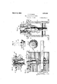
- the lower section or base 1 of the mold is in the form of a stand with side legs 2 and a 0 top in which the mold cavity 4 is formed.
- the mold cavity 4 has an open cylindrical bottom portion 5 in which fits a plunger 6 which carries an upwardly projecting core 7 t its upper end.
- the plunger (3 has a down- '"zu'dly extending stem 8 which fits in an opening in a cross bar 9 connecting the legs 2 ljacent their lower ends.
- a lever 10 is pivoted upon cross pin 11 extending between the legs :2 adjacent one side thereof 7 and extends through an opening 12 in the stem 8.
- a cross pin 13 extends through the plunger 6 and serves to positively limit the upward movement of the plunger.
- the upper and lower edges of the opening 12 are 7 rounded so that the lever 10 does not bind therein when swung about its pivot.
- the pin 18 is in engagement with the bottom of the mold as shown in Fig. 1 the plunger 6 and core 7 being movable downwardly from this position to that shown in l? ig. 2 "to free the core from the castin
- the upper mold section 14 has handles 15 by means of which it can be readily lifted oil i. bottom section '1. and has a lower flange 16 adapted to lit within the upper portion of lhe mold cavity 4.
- lhe mold section 14 has a central bore 17 ri h apers slightly toward the bottom to to removal of the casting and spruc, ell understood.
- the mold section 14 also provided with an annular air chamoer 22 preferably with outside openings therein.
- An easy method of providing such a chamber is to form a tubular liner 18 with thin intermediate portion 21 spaced from the wall of the bore 17, and thick up or and lower edge portions 19 and 20 fitting tightly in the bore 17.
- the mold is assembled as shown in Fig. 1, the inner bore of the liner 18 forms the mold gate and sprue recess,the annular passage between the core 7 and the lower portion of the liner 18 forming the gate and the remainder of the bore the sprue recess.
- both the core 7 and the inner bore of the liner 18 forming the sprue recess are tapered slightly toward the top so that the core can be pulled downwardly out of the casting and the sprue can be readily freed from the mold.
- a fluid passage 31 Surrounding the mold cavity and prefer ably located near the heavy section of the casting and remote from the gate a fluid passage 31 to carry any suitable fluid, pref erably a liquid such as water or oil, therethrough to cool the mold and consequently to cool the molten metal remote from the gate or in the heavy sections of the casting.
- This passage may follow the shape oi. the mold cavity and be formed in any suitable manner as by cores when casting the mold, or it may be formed of a rectangular shape, as shown in Fig. 7, by boring into the mold after the mold has been cast.
- the mold sections will be assembled as shown in Fig. 1 and molten metal will be poured in at the top until both the cavity t in the lower section and the s rue cavity are filled.
- additional metal is supplied from the sprue cavity. It has heretofore been necessary to provide a rather large sprue recess to maintain a sufi'icient reserve supply of molten metal and to have a sprue recess of a sufficient diameter that the center of the sprue would remain fluid long enough to supply the necessary metal to the mold cavity.
- the present invention provides a construction for the sprue cavity which retards the loss of the heat in the sprue and delays freezing until after the casting has hardened in the mold. cavity and thus permits the relatively small amount of metal in the sprue cavity to properly feed the solidifying casting.
- the annular air chamber 22 surrounding the sprue cavity retards the loss of heat for it decreases the volume of metal f r directly conducting the heat away from the sprue cavity so that the metal in the sprue may be nuiintained molten for a longer period oftime and a relatively larger percentage of the sprue metal is available for feeding the casting.
- any suitable fluid such as compressed air, can be circulated around the passage 22 through the openings 30, thus greatly reducing the time of waiting after the casting is solidified and until the sprue is sufiiciently solidified to remove the core 7.
- the sprue may be kept molten a sullicient length of time to properly feed the casting on solidification and may then be rapidly cooled to facilitate production.
- the annular passage may be designed to balance the time for keeping the metal molten in the sprue as long as necessary and permitting it to cool and solidify immediately thereafter without the use of a circulating fluid.
- castings may be made according to this invention in. which the is of relatively small cross'sectional area or in which all parts of the gate are relatively narrow, so that the tendency to form pipes is prevented and the character of the metal in the casting is improved.
- the method of forming castings having thin and thick sections of metal of relatively high crystallization shrinkage and relative- 1y 10W freezing point which consists in introducing molten metal of such characteristies into a permanent mold having a mold cavity and sprue cavity, retarding the escape of heat from the sprue cavity and facilitating the escape of heat from the thicker sections of the casting, and then accelerating the cooling of the metal in the sprue cavity after the metal in the mold cavity has solidified.
- the method of forming castings of relatively high crystallization shrinkage and relatively low freezing point which consists in introducing molten metal of such characteristics into a permanent mold having a mold cavity and sprue cavity, retarding the escape of heat from the sprue cavity until after the mold cavity is filled and the metal therein has substantially solidified.
Description
March 20, 1928.
C. VAUGHAN MOLD AND METHOD OF CASTING Filed Feb. 7, 1 923 2 Sheets-Sheet 1 I nus-11 707?. W s I 6mm B)- Z t Vow- March 20, 1928. 1,663,286 I C.VAUGHAN MOLD AND METHOD OF CASTING Filed Feb. 7, 1923 2 Sheets-Sheet. 2
Patented Mar. 20. 1928.
UNITED I srn'rss PATENT OFFICE.
CONRAD \FAUGHAN, CF CLEVELAND, OHIO, ASSIGNOR TO THE PERMOLD COMPANY, OF CLEVELAND, 01110, A CORPORATION OF OHIO.
MOLD AND METHOD OF CASTING.
Application fil d February This invention re '1 molds and a method. of forming castings, the i. ivention being particularly useful in fornr lug castings of aluminum alloys alloys having relatively high crystallization shrinkage and relatively low lfreezing point.
An obj ;ct of the lure on to retard he conduction of heat from that part of the l torn ing the srue cayity so the the using of the metal the spruc cavity is carded and smaller amount of metal sorue is required for properly fee-1 1 1 p e casting as it solidifi s in the znoro. c;
hes to permanent metal roperly fed because freezi of the mo 7 is retarded no l r the metal has solidified in the mold ity.
to provide a mold in may be made in due to the use or ation temperature l r will be a smmler excess of metal in the spine cavity.
A further object of the invention to i .o a mold in which the time for solidi- 1. L' o 3 a relative sins: V c v. 1 o snrjuo and in Arno.- we o.4 i Y zxve, J0 Lkllob I ape or the casting I the: ob ects in. iiOWlIlfl oescrmti ii Reference should be 1 I forming i. and
the upper and lower mo tZo-ns, shown in Figs. 2 a a) a plane at right angles to that shown in Fig. 1.
Figs. -1- and 5 are a side elevation and bet- 7, 1923. Serial No. 617,439.
tom plan view, respectively, of a casting formed in the mold.
Fig. 6 is a plan view of the mold after the metal has solidified therein.
Fig. '7 is a section on line 7-7, Fig. 1.
Referring to the accompanying drawings, the lower section or base 1 of the mold is in the form of a stand with side legs 2 and a 0 top in which the mold cavity 4 is formed. The mold cavity 4 has an open cylindrical bottom portion 5 in which fits a plunger 6 which carries an upwardly projecting core 7 t its upper end. The plunger (3 has a down- '"zu'dly extending stem 8 which fits in an opening in a cross bar 9 connecting the legs 2 ljacent their lower ends. A lever 10 is pivoted upon cross pin 11 extending between the legs :2 adjacent one side thereof 7 and extends through an opening 12 in the stem 8. A cross pin 13 extends through the plunger 6 and serves to positively limit the upward movement of the plunger. The upper and lower edges of the opening 12 are 7 rounded so that the lever 10 does not bind therein when swung about its pivot. When the mold core is in operative position for casting, the pin 18 is in engagement with the bottom of the mold as shown in Fig. 1 the plunger 6 and core 7 being movable downwardly from this position to that shown in l? ig. 2 "to free the core from the castin The upper mold section 14 has handles 15 by means of which it can be readily lifted oil i. bottom section '1. and has a lower flange 16 adapted to lit within the upper portion of lhe mold cavity 4.
lhe mold section 14 has a central bore 17 ri h apers slightly toward the bottom to to removal of the casting and spruc, ell understood. The mold section 14 also provided with an annular air chamoer 22 preferably with outside openings therein. An easy method of providing such a chamber is to form a tubular liner 18 with thin intermediate portion 21 spaced from the wall of the bore 17, and thick up or and lower edge portions 19 and 20 fitting tightly in the bore 17.
hen the mold is assembled as shown in Fig. 1, the inner bore of the liner 18 forms the mold gate and sprue recess,the annular passage between the core 7 and the lower portion of the liner 18 forming the gate and the remainder of the bore the sprue recess. To facilitate the removal of castings from the mold both the core 7 and the inner bore of the liner 18 forming the sprue recess are tapered slightly toward the top so that the core can be pulled downwardly out of the casting and the sprue can be readily freed from the mold.
Surrounding the mold cavity and prefer ably located near the heavy section of the casting and remote from the gate a fluid passage 31 to carry any suitable fluid, pref erably a liquid such as water or oil, therethrough to cool the mold and consequently to cool the molten metal remote from the gate or in the heavy sections of the casting.
This passage may follow the shape oi. the mold cavity and be formed in any suitable manner as by cores when casting the mold, or it may be formed of a rectangular shape, as shown in Fig. 7, by boring into the mold after the mold has been cast.
In operation, the mold sections will be assembled as shown in Fig. 1 and molten metal will be poured in at the top until both the cavity t in the lower section and the s rue cavity are filled. As the solidification of the metal in the mold cavity takes place, additional metal is supplied from the sprue cavity. It has heretofore been necessary to provide a rather large sprue recess to maintain a sufi'icient reserve supply of molten metal and to have a sprue recess of a sufficient diameter that the center of the sprue would remain fluid long enough to supply the necessary metal to the mold cavity. The present invention, however, provides a construction for the sprue cavity which retards the loss of the heat in the sprue and delays freezing until after the casting has hardened in the mold. cavity and thus permits the relatively small amount of metal in the sprue cavity to properly feed the solidifying casting. The annular air chamber 22 surrounding the sprue cavity retards the loss of heat for it decreases the volume of metal f r directly conducting the heat away from the sprue cavity so that the metal in the sprue may be nuiintained molten for a longer period oftime and a relatively larger percentage of the sprue metal is available for feeding the casting.
That the metal for feeding the casting is drawn from sides of the sprue as well as down through the center, as is usual, is shown by the shape of solidified. sprue metal in Figs. 2 and 4;, wherein the side 28 is concaved all the way around. In Fig. 4: the casting 24; is shown in full lines and the sprue 25 in dotted lines, the casting 2% after the sprue is removed having a central aperture 26.
If it is desired to hasten the cooling and solidification of the metal in the sprue after neeaaee the casting is solidified, any suitable fluid, such as compressed air, can be circulated around the passage 22 through the openings 30, thus greatly reducing the time of waiting after the casting is solidified and until the sprue is sufiiciently solidified to remove the core 7.
It will thus be seen that by varying the size of the annular passage surrounding the sprue cavity, the length of time that the sprue metal may be held in molten condition can be varied. Also by varying the temperature or quantity of iluid supplied to the body of the mold, the cooling time of the casting itself may be varied. Also by the circulation of air through. the annular passage 22 surrounding the sprue cavity, the time of solidification of the .sprue after the casting is solidified may be decreased so that the core may be removed more quickly. By providing these variables it is possible to design molds for many shapes of casting which will greatly increase the production yield per mold per day for provision can he made for removing heat as fast as desirable from the heavier sections of the casting or sections more remote from the gate. And the sprue may be kept molten a sullicient length of time to properly feed the casting on solidification and may then be rapidly cooled to facilitate production. Or if desired, the annular passage may be designed to balance the time for keeping the metal molten in the sprue as long as necessary and permitting it to cool and solidify immediately thereafter without the use of a circulating fluid.
Furthermore, it will be noted that by providing means for retarding the cooling of the metal in the sprue a relatively less amount of metal is necessary for properly feeding the casting for a relatively larger percent of the metal in the sprue is available for this purpose. It will thus be seen that castings may be made according to this invention in. which the is of relatively small cross'sectional area or in which all parts of the gate are relatively narrow, so that the tendency to form pipes is prevented and the character of the metal in the casting is improved.
l urthermore, it is to be understood that the particular forms of: apparatus shown and described, and the particular procedure set forth, are presented for purposes of explanation and illustration and that various modifications of said apparatus and procedure can be made without departing from my invention as defined in the appended claims.
lVhat I claim is:
1. The method of forming castings of metal of a relatively high crystallization shrinkage and a relatively low freezing point which consists in introducing molten metal of such characteristics into a permanent mold having a mold cavity and sprue cavity, cooling the mold adjacent the more remote sections 01" the casting and then cooling that portion of the mold surrounding the sprue cavity.
2. The method of forming castings having thin and thick sections of metal of relatively high crystallization shrinkage and relative- 1y 10W freezing point, which consists in introducing molten metal of such characteristies into a permanent mold having a mold cavity and sprue cavity, retarding the escape of heat from the sprue cavity and facilitating the escape of heat from the thicker sections of the casting, and then accelerating the cooling of the metal in the sprue cavity after the metal in the mold cavity has solidified.
3. The method of forming castings of relatively high crystallization shrinkage and relatively low freezing point, which consists in introducing molten metal of such characteristics into a permanent mold having a mold cavity and sprue cavity, retarding the escape of heat from the sprue cavity until after the mold cavity is filled and the metal therein has substantially solidified.
In testimony whereof, I hereunto aflix my signature.
CONRAD VAUGHAN.
Publications (1)
| Publication Number | Publication Date |
|---|---|
| US1663286A true US1663286A (en) | 1928-03-20 |
Family
ID=3414732
Family Applications (1)
| Application Number | Title | Priority Date | Filing Date |
|---|---|---|---|
| US1663286D Expired - Lifetime US1663286A (en) | vaughan |
Country Status (1)
| Country | Link |
|---|---|
| US (1) | US1663286A (en) |
-
0
- US US1663286D patent/US1663286A/en not_active Expired - Lifetime
Similar Documents
| Publication | Publication Date | Title |
|---|---|---|
| US3421569A (en) | Continuous casting | |
| US1663286A (en) | vaughan | |
| US1920854A (en) | Heat insulating means for use in producing metallic castings | |
| US1696986A (en) | Hot top for molds | |
| US2119242A (en) | Method and apparatus for casting | |
| US1645731A (en) | Mold | |
| US1393195A (en) | Billet-casting | |
| US1387291A (en) | Method and means tor billet-casting | |
| US2248868A (en) | Method and apparatus for preparing metal castings | |
| US2367148A (en) | Continuous casting | |
| US2088696A (en) | Means for producing ingots | |
| US1961721A (en) | Casting method | |
| US2097658A (en) | Apparatus to be used in casting metal | |
| US2621380A (en) | Piston casting machine | |
| US2737696A (en) | Method of producing sound ingots of fully killed steel in big-end-down molds | |
| US1961529A (en) | Casting ingots | |
| US1458222A (en) | Method of gating castings | |
| US2750641A (en) | Chill | |
| CN210547861U (en) | Fired mold with local quick cooling structure | |
| US2113585A (en) | Method for casting pistons | |
| US1560036A (en) | Method and apparatus for casting ingots | |
| US2276018A (en) | Metal founding | |
| US1819705A (en) | Ingot mold | |
| US2169797A (en) | Method of casting, self-stripping and rapid-cooling steel ingots | |
| US2419873A (en) | Mold and core and method of casting in same |