US1663258A - Electrode clamp - Google Patents
Electrode clamp Download PDFInfo
- Publication number
- US1663258A US1663258A US6046A US604625A US1663258A US 1663258 A US1663258 A US 1663258A US 6046 A US6046 A US 6046A US 604625 A US604625 A US 604625A US 1663258 A US1663258 A US 1663258A
- Authority
- US
- United States
- Prior art keywords
- electrode
- seat
- clamping
- passage
- arm
- Prior art date
- Legal status (The legal status is an assumption and is not a legal conclusion. Google has not performed a legal analysis and makes no representation as to the accuracy of the status listed.)
- Expired - Lifetime
Links
Images
Classifications
-
- B—PERFORMING OPERATIONS; TRANSPORTING
- B23—MACHINE TOOLS; METAL-WORKING NOT OTHERWISE PROVIDED FOR
- B23K—SOLDERING OR UNSOLDERING; WELDING; CLADDING OR PLATING BY SOLDERING OR WELDING; CUTTING BY APPLYING HEAT LOCALLY, e.g. FLAME CUTTING; WORKING BY LASER BEAM
- B23K11/00—Resistance welding; Severing by resistance heating
- B23K11/30—Features relating to electrodes
- B23K11/31—Electrode holders and actuating devices therefor
-
- Y—GENERAL TAGGING OF NEW TECHNOLOGICAL DEVELOPMENTS; GENERAL TAGGING OF CROSS-SECTIONAL TECHNOLOGIES SPANNING OVER SEVERAL SECTIONS OF THE IPC; TECHNICAL SUBJECTS COVERED BY FORMER USPC CROSS-REFERENCE ART COLLECTIONS [XRACs] AND DIGESTS
- Y10—TECHNICAL SUBJECTS COVERED BY FORMER USPC
- Y10T—TECHNICAL SUBJECTS COVERED BY FORMER US CLASSIFICATION
- Y10T279/00—Chucks or sockets
- Y10T279/17—Socket type
- Y10T279/17393—One movable side
- Y10T279/17401—Sleeved
Landscapes
- Engineering & Computer Science (AREA)
- Mechanical Engineering (AREA)
- Clamps And Clips (AREA)
Description
March 20, 1928.
J. W. MEADOWCROFT ELECTRODE CLAMP Filed Jan. 31, 1925 5 mm P Patented Mar. 20, 1928.
UNITED STATES 1,663,258 PATENT OFFICE.
.rosnrrr w. mowcnor'r, or rnrnannnrnm, rnnnsrnvama, assronoa To anwann a. BUDD MANUFACTURING 00., or PHILADELPHIA, rmmsnvmm. a con- POBATION or PENNSYLVANIA.
unc'rnonn mm.
Application filed January 81, 1925. Serial l'o. 8,048.
My invention relates to an improved device for releasably looking or clamping in position the' electrodes used in electrical welding machines. As is' Well known by 6 those familiar with the art, these electrodes are usually held in lace by set screws or by wedges which are a apted to be driven tightly in place between the electrode and its seat. The use of set screws makes'it very 0 diflicult to securely position the electrode in its arm or holder against displacement, since the screws are. apt to become loosened under the continual pounding of the electrodes on the work. In consequence of this displacement of the welding electrodes in their seats the welding machine may be entirely put out of commission.
The use of wedges adapted to be driven a inst the electrode has its disadvantagles :0 so. It is the usual practice when using t is type of securing means to force the wedges in against the electrode so tightly that they are not easily removable. It is often the case that the electrodes are only able to be removed after theoperator has hammered at the electrode supporting arm in order to start the wedges. This means that the arm, which is made of copper and easily dented, is more or less injured.
A common practice for seating the electrode in its seat has been toprovide screw threads on its surface so that it may be threadedly received within a socket. Such a threaded surface has proved to be a ready as collecting medium for the molten copper which is spattered about during the welding operations. This molten metal settles between the threads on the electrode so as to destroy their effectiveness, and, as is often the case even with smooth surfaced electrodes, tends to cement the electrode to its holder. In either event ready removal or replacement of the electrode from or in its holder is prevented. By means of my invention it becomes possible to use an electrode which has a smooth surface such as would ofier a minimum of attraction for the objectionable free molten metal. It is an object of my invention to provide a clamping de- 0 vice for supporting an electrode in its seat which will not be rendered inoperative and useless because of the continual splattering of molten metal thereupon during the weldoperations.
It is another object of this invention to in its supporting arm which may be as easily released as 1t 18 applied. A further object is to facilitate adjustment of the electrode, and.
its removal if that is desired. A still further object of my invention is to provide a new type of wedging means whereby the use of a driving force in the hands of the operator such as a hammer, mallet or similar device is avoided. Other objects of my invention will appear more fully hereinafter.
Inthe accompanying drawings:
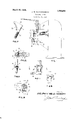
Fig. 1 is a side elevation of a welding machine showing the a plication thereto of the electrode clamping evice embodying my invention.
Fig. 2 is a sectional view of the clamping device on the line 22 of Fig. 1.
Fig. 3 is a sectional view of the clampin device on the line 3+3 of Fi 1.
Fig. 4 is a side elevation 05 another application of the electrode clamping device.
'Fig. 5 is a sectional view through the clamp taken on the line 5-5 of Fig. 4.
Fig. 6 is a sectional view through the clamp taken on the line 66 of Fig. 5, and Fig. 7 is a perspective view of the clamping element itself as used in Figs. 4, 5 and 6.
In the drawings, the same reference numerals refer to similar parts throughout the several views.
In general, my invention consists in the provision of an electrode clamping device for securing an electrode in its supporting arm. This clamping device is essentially one of the Wedge type wherein the electrode seat. The electrode seat is formed by providing an opening through the copper arm of the welding machine which opening extends vertically through said arm. The electrode is adapted to be more or less loosely fitted into said opening. Transversely disosed with respect to this vertically extendmg electrode seat or opening, is a passage extending through from one side of the arm to the other side. This passage, while it is continuous in extent, is in reality in two separate parts, one part of which is in the shape of a slot which is in communication with a portion of the electrode seat. The other part of this passage is merel an opening leading from the mner side 0 said slot to the far 'is, by means of the wedge, forced into its side of the supporting arm. It is in alignment with that end of the slot which is not in communication with the electrode seat.
A wedging member which is to be more specifically described hereinafter is adapted to be fitted into the above described slot or recess and a means is provided for positively drawing the wedging member into the slot and so into the electrode receiving opening.
Fig. 1 shows generally, as is indicated by the reference character A, a welding machine of the usual type in which my invention is applied. This machine is provided with the welding electrodes 10-10 which are'secured in their respective supporting arms 11-11 by the clamping means indicated generally by the reference numeral 12.
Figs. 2 and 3 show a particular form of m invention in which the arm of the elec-' tric welding machine is indicated by 11. At the outer end of this arm is provided a vertically extending opening 13 through which freely extends the electrode 10. To one side of this vertically extending opening 13 is provided a passage let extending at right angles thereto. This passage extends halfway through'the electrode supporting arm. At the inner end of the passage 14 is provided a continuation thereof in the form of a. slot indicated by 15. The side of the slot 15 which is offset from the axis of the passage 14: communicates with the'opening 13 for the purpose to be hereinafter explained. The wall of the slot which is removed from the opening 13 is tapered as is indicated by 16.
The wedge for use in my invention is, as shown in Figs. 2 and 3, comprised of two separate parts, in which 17 is the wedge element per se and 18 is a member (in this case in the form of abolt) for drawing the wedge into engagement with the electrode. The wedging element 17 is provided with an opening 19 through which the bolt 18 projects when the wedge element is in place in its seat. One edge of the wedging element is tapered as indicated at 20 to correspond with the tapered wall 16 of the recess-15. Opposite to this tapered edge, the Wedging element is provided with an arched surface 21 which engages the electrode on the quarter nearest itself.
In the use of my device, as shown in Figs. 2 and 3, the electrode is positioned in its seat 13 in the arm 11 and by means of the bolt 18 and nut 18, the wedging element is drawn into its receiving recess 15 in such manner that the arched surface 21 thereof engages the curved surface of the electrode and the coinplementally tapered surfaces 15 and '16 act to force it tightly into its seat.
Figs. 4, 5, 6 and 7 show the preferred embodiment of my invention. The electrode supporting member comprising the arm with its vertically extending opening. transversely extending passage and the offset recess is neeaeaa' Figs. 1 and 5 show in invention as applied spccifically to an e ement in an automatic circuit maker and breaker wherein the electrode is the contact element and wherein the clamping device acts to securely hold this contact element in place. Except for this and the addition of the base 30, the electrode supporting structure is the same as has been above described. There is provided the same transversely extending passage 14, as was described before, together with the recess 15 which is in communication with the electrode seat- 13. In each case it is designed that the thickness of the head be uniformly equal to the diameter of the screw-threaded shank.
In use, the device as described in Figs. 4: to 7, is exactly like that of Figs. 2 and 3. The shank 25 of the wedge member is inserted through the passage 14 at the same time seating the head 26 in the recess 15. A nut 31 is threaded upon the projecting end of the shank 25 with alock Washer in advance. Him the nut is tightened the wedge 26 is not only drawn in toward the electrode seat 18 in such manner that the serrated surface 28 has a wedging engagement with the surface of the electrode, but also the tapered surfaces 15 and 16 will force the serrations 29 over toward and cause them to bite strongly into the engaged surface of the electrode. So the electrode is not only clamped firmly in its seat but is also firmly locked against axial displacement under the heavy welding pressures. v i
It will be at once apparent that by means of my clamping device, the electrode is clamped in position by forces applied to it in two different directions. One of these forces is purely a wedging force due to the action of the tapered edge of the head 27 acting on the wall of the passage 14 and the other of these forces is that due to the drawing force of the offset portion of the head 26 in a line substantially parallel to the shank. The resultant force is applied to the electrode by my wedging means to securel and posi tlvely clamp it in position by tig itening the nut 18 as in Fig. 2 or 25 as in Fig. 5.
This resultant force is applied to the surface of the electrode in a direction and on a line through the arched surface of the possible for the wedging element to engage" the surface of the electrode at more than just a single point, thus insuring a much better contact than has heretofore been possible.
I am aware that the embodiment which I have shown and described may be varied sa e extendingthrough said holder to one si e of said seat-and, said passage having an off-set portion in communication wit said I seat, ,an electrode clamping member having, one arm projecting through said transverse passage and another arm seated in theofiset portion thereof, the rear edge of the second-mentioned arm bein inclined with respect to the axis of the rst-mentioned arm.
2. As an article of manufacture, an electrode clampin element comprising a screwthreaded sha a head havin an offset por-' tion integrally formed therewith, an inclined surface at the base of said head, and a nut.
coacting with said screw threaded shank whereby to lock the clamping element in engagement with the electrode.
3. As an article of manufacture, an electrode clamping element comprising a screw threaded shank, a head having an offset portion integrally formed therewith, an inclined surface at the base of said head and an arched, clamping surface atthe inner side of said offset portion, and a nut coacting with said screw threaded shank whereby to lock the clamping element in engagement with the electrode.
4. In adevice of the class described, an electrode holder provided with a seat for the reception of an electrode, a transverse pas sage at one side of. said seat, an electrode clamping member movable insaid passage and aving an extended arc of contact with the electrode, and means for advancin said clamping member radiall of its are 0 contact toward the center 0 the electrode.
5. In adevice of the class described, an electrode holder provided with a seat for the reception of an electrode, 'a transverse passage at one side of said seat having an inclined wall, an electrode clamping member having an offset rear edge coacting with an inclined wall of its passage, and means for advancing said clamping member in said passage, whereby the resultant of the clamping force is at an angle to the passage.
6. As an article of manufacture a clamping member havin an are shaped clamping surface and provi ed with means for application of clampin force eccentrically of said are shaped sur ace and' also with means to translate the eccentrically applied force y to concentrically applied force.
7. As an article of manufacture a clamping member having an are shaped clamping surface, said arc shaped surface being longitudinally serrated throughout the length of the arc and provided with means for'application of clampin force eccentrically of said are shaped sur ace and also with means to translate the eccentrically applied force to concentrically applied force.
In testimony whereof I hereunto aflix my signature. y
, J OSEl-THv W.. MEADOVK'CROFT.
Priority Applications (1)
| Application Number | Priority Date | Filing Date | Title |
|---|---|---|---|
| US6046A US1663258A (en) | 1925-01-31 | 1925-01-31 | Electrode clamp |
Applications Claiming Priority (1)
| Application Number | Priority Date | Filing Date | Title |
|---|---|---|---|
| US6046A US1663258A (en) | 1925-01-31 | 1925-01-31 | Electrode clamp |
Publications (1)
| Publication Number | Publication Date |
|---|---|
| US1663258A true US1663258A (en) | 1928-03-20 |
Family
ID=21719024
Family Applications (1)
| Application Number | Title | Priority Date | Filing Date |
|---|---|---|---|
| US6046A Expired - Lifetime US1663258A (en) | 1925-01-31 | 1925-01-31 | Electrode clamp |
Country Status (1)
| Country | Link |
|---|---|
| US (1) | US1663258A (en) |
Cited By (1)
| Publication number | Priority date | Publication date | Assignee | Title |
|---|---|---|---|---|
| US2850789A (en) * | 1953-07-16 | 1958-09-09 | Baker Brothers Inc | Automatic material working machine |
-
1925
- 1925-01-31 US US6046A patent/US1663258A/en not_active Expired - Lifetime
Cited By (1)
| Publication number | Priority date | Publication date | Assignee | Title |
|---|---|---|---|---|
| US2850789A (en) * | 1953-07-16 | 1958-09-09 | Baker Brothers Inc | Automatic material working machine |
Similar Documents
| Publication | Publication Date | Title |
|---|---|---|
| US3084416A (en) | Cutting tool | |
| US4462725A (en) | Metal cutting tools with replacement insert | |
| US2574007A (en) | Clamping device | |
| US3623201A (en) | Rake toolholder | |
| US1810901A (en) | Weldrod holder for electric arc welding | |
| US3654682A (en) | Tool holder | |
| US2055295A (en) | Apparatus for attaching printing plates to a cylinder | |
| US2595090A (en) | Cutting tool | |
| US1663258A (en) | Electrode clamp | |
| US2140192A (en) | Hole saw blade | |
| US2683302A (en) | Toolholder | |
| US1376077A (en) | Machine-clamp | |
| US2173698A (en) | Form tie clamp | |
| US3459433A (en) | Replaceable jaw inserts | |
| US3801213A (en) | Adjustable dovetail boring bar | |
| US5163693A (en) | Top jaw and wedge connector | |
| US3220089A (en) | Holders for cutting inserts | |
| US3207015A (en) | Cutting tool adjustment assembly | |
| US2483096A (en) | Boring tool | |
| US1558036A (en) | Tool | |
| US2556723A (en) | Toolholder | |
| US4083645A (en) | Tool holder | |
| US2657066A (en) | Tool holding collet for boring bar assemblies | |
| US2636529A (en) | Razor blade plane | |
| US3112659A (en) | Interchangeable head boring bar |