US1663235A - Game - Google Patents
Game Download PDFInfo
- Publication number
- US1663235A US1663235A US174761A US17476127A US1663235A US 1663235 A US1663235 A US 1663235A US 174761 A US174761 A US 174761A US 17476127 A US17476127 A US 17476127A US 1663235 A US1663235 A US 1663235A
- Authority
- US
- United States
- Prior art keywords
- buffer
- run
- way
- game
- ball
- Prior art date
- Legal status (The legal status is an assumption and is not a legal conclusion. Google has not performed a legal analysis and makes no representation as to the accuracy of the status listed.)
- Expired - Lifetime
Links
Images
Classifications
-
- A—HUMAN NECESSITIES
- A63—SPORTS; GAMES; AMUSEMENTS
- A63D—BOWLING GAMES, e.g. SKITTLES, BOCCE OR BOWLS; INSTALLATIONS THEREFOR; BAGATELLE OR SIMILAR GAMES; BILLIARDS
- A63D3/00—Table bowling games; Miniature bowling-alleys; Bowling games
Landscapes
- Pinball Game Machines (AREA)
Description
March 20, 1928. 1,663,235
A. c. BARNES GAME Filed March 12, 1927 2 Sheets-Sheet 1 March 20, 1928;
A. C. BARNES GAME Filed March 12, 1927 2 Sheets-Sheet Z Inventor forneu Patented Mar. 20, 1928.
AarHna c. BAnNEs. or BALTIMORE, MARYLAND.
GAME.
Application filed March 12, 1927. Serial No. 174,761.
This invention relates to improvements in games and has a special reference to a bowling table. The object of this invention is to provide a game for the amusement of young 6 and old and which is simple in construction and easily operated.
The invention consists of the novel construction and arrangement of the parts and combination of the parts hereinafter more fully set forth in the following specifications and pointed out in detail in the appended claims.
In the accompanying drawing:
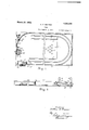
Figure 1 is a plan view of my invention,
partly broken away.
Figure 2 is a side elevation of Figurefl.
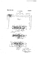
Figure 3 is a top plan view of the mechanism for discharging the balls, the top cover being removed therefrom.
Figure 4 is a section on the line 2-2 of Figure 3 with the top cover in position.
Figure 5 is a detail view of the ball discharging mechanism in position on the table.
Figure 6 is a detail rear viewof the adjustable guide mechanism.
Referring to the accompanying drawing, forming part of this specification, and in which like reference numerals designate like parts throughout the several views thereof, 1
designates a table having legs 2. The upper surface of the table is provided with a runway 3, a pit 4 and two short run-ways 5. The upper surface of the table adjacent said pit 4 is provided with circles 6 to indicate 5 the position of the tenpins thereon. The front end of the table is provided with a ball discharging mechanism in line with one end of the run-way 3. The said ball discharging mechanism consists of the base 7 to which is bolted the bearings 8 and 9. The rods 10 project through the bearings 8 and 9 and are provided with springs 11 and 12 which hold them in their normal position. One end of said rods 10 is provided with a cross-head 13 to the outer surface of which is secured a 1 buffer 14. The base 7 is provided with two projecting spring fingers 15 which extend-beyond the buffer 14 and can be adjusted by means of the screws 16. The balls to be used are placed between the fingers 15 against the buffer 14 and are held in this position by means of the spring fingers 15. A crosshead 17-is secured to, and movable with, the
rods '10. The said cross-head 17 is provided with an aperture 18 in which the pin 19 operates. On the lower surface of the base 7 is a bearing 20 in which the shaft 21 is mounted. The said shaft 21 is provided with a cam 22 to which is secured a plate 23 which carries a roller 24 on its upper end. The said shaft 21 isoperated-by means of the handle 25, the latter being held in its normal raised position by means of the springs 26. When the ball is placed between the, spring fingers 15 against the buffer 14, thehandle 25 is pressed down which causes the roller 24 to strike the pin 19 and carry the rods 10 back against the action of the springs 11,
v and when the roller reaches a certain position the pin 19 will be forced up on top of the cam 22 at which point the springs 11 will force the rods 10 back to their normal position with sufficient force to cause the buffer 14 to strike the ball causing the latter to be driven around the run-way 3 to the adjustable guide 27 and on to the pins. When the handle 25 is returned to its normal raised position the cam 22 will be brought back and the pin allowed to drop down to its normal position as shown in Figure 4. A plate 28 is secured to the top of the bearings 8 and 9 and is provided with a spring 29 which operates against the upper end of the pin 19 tohold thelatter in its normal position. At
one end of the run-way 3 is a stationary guide 30 against which the balls strike when they pass from the run-way 3 and are carried to the adjustable guide 27. The said adjustable guide 27 has a plate 31 near one end thereof which is provided with an elongated slot 32 through which the screw 33 passes. The opposite end of the adjustable guide 27 is connected by a rod 34 to the wheel 35 which latter is provided with handles 36. The said wheel 35 is pivoted to the top of the table and is provided with a brake-shoe 37 which is held normally against the wheel 35 by the spring 38. I
When it is desired to play the game the ten pins are placed in the position on the circles 6. The ball is then placed between the spring fingers15 against the buffer 14. The discharging mechanism is then operated by the lever 25, as heretofore described, which causes the ball to be forced around the run-way 3 against the stationary guide 30, then to the adjustable guide 27 from which latter it passes to the ten pins, the
angle at Which the ball is discharged from the adjustable guide 27 being'determined by the position to which the guide 27 is adjustable by means of the wheel 85. The balls fall-into the pit 4. I j H Having thus described my invention what I claim is:
1. A game comprising a base having a run-way extending around part of the sides and one end thereof, a stationary guide secured to the upper surface of the table at one end of said run-way, an adjustable guide having one end adjustably secured to the table at the end of said stationary guide, a wheel pivoted to the upper surface of said table, arod connecting said wheel with one end of the adjustable guide, a buffer mounted at one end of said run-way, a shaft mounted under said table having a handle on one end thereof, a cam on said shaft, and means connecting the buffer with said shaft whereby when the handle is forced down the buffer will be operated to discharge the ball from the run-way.
2. A game comprising a table having a run-way around the sides and one end there of, a stationary guide at one end of said runway, an adjustable guide adjacent to said stationary guide, a wheel revolubly mounted on top of said table, a rod connecting said wheel with said adjustable guide, a brakeshoe for holding the wheel in the adjusted position, 'a buffer mounted at the other end of said run-way, two spring fingers projectposition, a buffer mounted at the other end shaft mounted under said table and having a handle on one end thereof, a cam mounted on said shaft, and means connecting the buffer with said shaft whereby when the handle is forced down the buffer will be operated to discharge the ball from the runway. I
In testimony whereof I allix my signature.
ARTHUR C. BARNES.
Priority Applications (1)
| Application Number | Priority Date | Filing Date | Title |
|---|---|---|---|
| US174761A US1663235A (en) | 1927-03-12 | 1927-03-12 | Game |
Applications Claiming Priority (1)
| Application Number | Priority Date | Filing Date | Title |
|---|---|---|---|
| US174761A US1663235A (en) | 1927-03-12 | 1927-03-12 | Game |
Publications (1)
| Publication Number | Publication Date |
|---|---|
| US1663235A true US1663235A (en) | 1928-03-20 |
Family
ID=22637414
Family Applications (1)
| Application Number | Title | Priority Date | Filing Date |
|---|---|---|---|
| US174761A Expired - Lifetime US1663235A (en) | 1927-03-12 | 1927-03-12 | Game |
Country Status (1)
| Country | Link |
|---|---|
| US (1) | US1663235A (en) |
Cited By (1)
| Publication number | Priority date | Publication date | Assignee | Title |
|---|---|---|---|---|
| DE3405722A1 (en) * | 1984-02-17 | 1985-08-22 | Karl 8880 Dillingen Ernst | Skittle table |
-
1927
- 1927-03-12 US US174761A patent/US1663235A/en not_active Expired - Lifetime
Cited By (1)
| Publication number | Priority date | Publication date | Assignee | Title |
|---|---|---|---|---|
| DE3405722A1 (en) * | 1984-02-17 | 1985-08-22 | Karl 8880 Dillingen Ernst | Skittle table |
Similar Documents
| Publication | Publication Date | Title |
|---|---|---|
| US2432824A (en) | Game apparatus | |
| US1543318A (en) | Ball game | |
| US1374844A (en) | Game | |
| GB291044A (en) | An improved ball-throwing device | |
| US2207643A (en) | Bowling alley | |
| US2215687A (en) | Game apparatus | |
| US1785876A (en) | Catapult | |
| US2062204A (en) | Game apparatus | |
| US1663235A (en) | Game | |
| US3300215A (en) | Marble catapult and game board construction | |
| US2083540A (en) | Game | |
| US1296129A (en) | Combined toy and game apparatus. | |
| US1903254A (en) | Basket ball game | |
| US2528250A (en) | Marble runway game | |
| US2626154A (en) | Pin spotter for miniature bowling games | |
| US1432752A (en) | Bowling alley | |
| US1276475A (en) | Game. | |
| US1622156A (en) | Game | |
| US1368875A (en) | Game apparatus | |
| US3746341A (en) | Pin ball game apparatus with supplemental manual | |
| US2118383A (en) | Bowling game | |
| US1970068A (en) | Amusement device | |
| US1604047A (en) | Game apparatus | |
| US655583A (en) | Bowling-alley. | |
| US2155480A (en) | Tennis playing machine |