US1663200A - Resistance welding machine - Google Patents
Resistance welding machine Download PDFInfo
- Publication number
- US1663200A US1663200A US147556A US14755626A US1663200A US 1663200 A US1663200 A US 1663200A US 147556 A US147556 A US 147556A US 14755626 A US14755626 A US 14755626A US 1663200 A US1663200 A US 1663200A
- Authority
- US
- United States
- Prior art keywords
- spindle
- welding
- electrode
- flanges
- shaft
- Prior art date
- Legal status (The legal status is an assumption and is not a legal conclusion. Google has not performed a legal analysis and makes no representation as to the accuracy of the status listed.)
- Expired - Lifetime
Links
Images

Classifications
-
- B—PERFORMING OPERATIONS; TRANSPORTING
- B23—MACHINE TOOLS; METAL-WORKING NOT OTHERWISE PROVIDED FOR
- B23K—SOLDERING OR UNSOLDERING; WELDING; CLADDING OR PLATING BY SOLDERING OR WELDING; CUTTING BY APPLYING HEAT LOCALLY, e.g. FLAME CUTTING; WORKING BY LASER BEAM
- B23K11/00—Resistance welding; Severing by resistance heating
- B23K11/002—Resistance welding; Severing by resistance heating specially adapted for particular articles or work
- B23K11/0026—Welding of thin articles
Landscapes
- Engineering & Computer Science (AREA)
- Mechanical Engineering (AREA)
- Butt Welding And Welding Of Specific Article (AREA)
Description
March 20, 1928.
A. JONSSON RESISTANCE WELDING MACHINE 7 Filed Nov. 10, 1926 3 sheetssheet l E'Hilllll [1111111] March 20, 1928.
v A. JONSSQN RESISTANCE WELDING MACHINE 3 Sheets-Sheet 2 Filed NOV. 1 1926 //l/l /E/V 70/? A JdHSS on a M, y /w w W w March 20, 1928. 1,663,200
A. JONSSON RESISTANCE WELDING MACHINE Filed Nov. 10, 1926 3 Sheets-Sheet 3 //VI/E/V TOP? A. f077ss0n Patented Mar. 20, 1928.
* 1,663,200 UNITED STATES PATENT'OFFICE;
.um'ans aonsson; or' HELSINGBORG, swnnnn.
RESISTANCE WELDING MACHINE.
Application filed November 10, 1926, Serial No. 147,556, and in Sweden October 19, 1925.
The radiators for heating installations are in the present day made to a great extent of sheet metal instead of as previously ofcast iron, and such radiators are usually composed of sections having connection openings surrounded by flanges by means of which the sections are joined together by welding. Hitherto such welding of the sections has been carried out by means of weld- 1" ing burners.
The object of the present lnvention 1s to= provide a considerably quicker and cheaper method of welding the sections together. In addition, this new method includes the advantage that the welded seam becomes more even and has a better appearance externally than has hitherto been achieved by the older methods, so that any finishing or cleaning of the welded seam will not be required.
According to the present invention the welding is carried out electrically by means of electrodes which are positioned in place internally of the connection openings of the sections and which work upon the edges of the adjacent and abutting flanges to be joined, the welding of the said joints at both ends of the radiator sections being preferably carried out in a machine having a double set of electrodes.
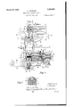
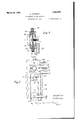
The invention is illustrated in the accompanying drawings, in which: Figure 1 shows one form of embodiment of a machine for carrying out the method according to the invention. Fig. 2 shows a section on the line IIII in Fig. 1 and seen in the direction of the arrows. Fig. 3 shows a section on the line III-III in Fig. 1 and seen in the direction of the arrows. Fig. 4 shows a section on the line IV IV in Fig. 3. Fig. 5 shows a front elevation and Fig. 6 shows a vertical section of a modified clamping device for the sections.
The machine as illustrated is adapted to simultaneously weld the flanges at both ends of the radiator sections and for this purpose it is provided with a double set of electrodes.
, Each electrode to be used for welding the said flanges internally is preferably constituted by a hollow roller 1 which is fixed so to the front end of a hollow mandrel 4 which is rotatably inserted in the bore-hole 3 of a hollow spindle 2, as clearly illustrated in Fig. 3. The spindle 2 is supported by a bearing or housing 5 and its front end of reduced diameter projects from said housing and is intended together with the electrode 1 thereon to be inserted through the connection openings 6 of the radiator sections 7 to be joined together. In the housin 5 is journalled a sleeve or hollow shaft 8 having a longitudinal groove like cavity 9 in which the spindle 2 being provided with flat surfaces on two opposite sides is insorted so that it is rotatable together with the sleeve 8 and maybe positioned in co-axial or eccentric relation to the latter. The front end of the sleeve 8, projecting from the hearing or housing 5 has a sto ring 10, and in a threaded hole through t e stop ring and the projecting end of thesleeve 8 is inserted a set screw 11 which forms with its inner end a radial support for the spindle 2, about which the latter may be rocked within certain limits. Diametrically opposite the said set screw 11 there is inserted in the stop ring 10 a helical spring 12 adapted to press the spindle towards the point of the screw 11. On the same side as the spring 12 but at the back end of the spindle 2 there is another spring 13 acting on the spindle 2. This spring 13 is relatively powerful and its tension should be adjustable, for instance as shown, by means of an adjusting screw 1d or the like. Diametrically opposite the said spring 13 the spindle 2 rests upon a pin 15 radially movable in a hole through the wall of a sleeve and abutting with its free end a bell crank lever 16 of which its other arm rests against a disc 17 which is axially reciprocable. When this disc has the position as shown in Fig. 3, the spindle 2 together withthe electrode 1 thereon is centered in relation to the housing 5 and also in relation to the connection openings in the radiator sections 7. WVhen however the disc 17 is movedbackwardly (to the right in the illustration) the pin 15 may move outwardly, so that the spindle 2 will be'rocked through the influence of the spring 13 about the point of the set screw 11 and thus receive an inclined position in which the electrode 1 will be eccentric in relation to the connection openings, that is a point of its circumference will be in contact with the edges 29 of. the flanges 30. The sleeve or hollow shaft 8 is connected by means of suitable sleeves orconduit connecting pieces with another hollow shaft 18 which is purnalled in a bearing 19 and provided at its projecting end with a bevel gear wheel 20. Both gear wheels 20 belonging to the two sets of electrodes 1 (Fig. 1) are in mesh "and to the same leads a piping 24 for a suitable cooling means, such as water, which is discharged from the hollow electrode through a passage 3 round about the piping 24: in the mandrel and thence through the hollow spindle 2 into the sleeve and finalliy through holes in the said sleeve into a ischar'ge trough 66 or the like, see Figs. 1 and 3. Other parts of the machine may naturally also be provided with similar cooling arrangements, if such are found to be desirable or necessary.
At least one of the two hearings or housings 5 may be moved towards or away from the other along guides 25, and further at least'one of the two supporting slides 26- having upright supports 33 may be moved towards or away from the other alon a guide 27 which is in front of and para lel with the guides 25. These guides 25 and 27 as well as other stationary parts of the machine are mounted in the usual way on a frame of which fractions are shown in Fig 3. Intermediate the two slides 26 there is provided a table or the like 28 for supporting the body of the radiator section during welding.
The radiator sections are placed with one of their longitudinal outer edges-on the table '28 and are psuhed in lateral direction with their connection openings 6 over the centered electrodes 1, so that the edges 29 of the connection flanges 30 on the said openings are in register With the electrodes 1, as shown in Fig. 3. To each of the slides 26 are pivotally attached centering cheeks 31 and 32, and these cheeks are swungupwardly into the position as shown with dash-dotted lines in Fig. 2, in which position they grip around the flanges center the same with respect to the axis of the electrode roller 1, when this latter is in centered position with respect to the housing or hearing 5. The said centering cheeks 31 and 32 constitute at the same time outer counter electrodes to the inner electrode 1. The innermost radia-. tor section 7, that is the section adjacent the housings or hearings 5 and which is to be welded on to the next to last section rests with its surfaces around the flanges 30 upon the upright supports 33 on the slides 26, to
which are pivotally attached clamping forks or the like 34- (see the dotted lines in Fig. 3) which are swung about their pivots 4:1 to grip the outer surface of the next to last section, as shown with dash-dotted lines in Fig. 1, and to press this said section against the last section. The sections being centered and secured in this manner, the discs 17 (Figs. 1 and 3) are moved backwards,
21 on a common whereby the pin'15 through the influence of the spring 13 is moved radially outwardly, so that the spindle 2 will be rocked about the point of the screw 11 "and thus receive an inclined position, so that the electrode 1 will have an eccentric position relatively to the connection openin s 6, that is it will be in contact with the edges 29 of the flanges 30. As the spindles 2 together with the electrode rollers 1 thereon are connected by means of the gearings 20, 21 with the intermittently rotated driving shaft 22, the electrodes 1 roll step by step along the edges 29 in a concentric path. The welding current to effect the weldin is in a manner known per se kept closed during the stand-still of the electrode rollers 1 and opened during the travel of the latter. In this manner the electrode rollers 1 are caused to travel at lest one revolution along their concentric paths in intimate contact with the edges 29 preferably'bent inwards, and if desired or considered necessary the electrode rollers may be caused to travel two or more revolutions in order to obtain a complete and satisfactory welding of the edges of the flanges 30. \Vhen the welding is completed the clamping forks and the centering cheeks are swung back into their initial positions, as shown with full lines in F igs; 1 and 3, and the electrode rollers 1 are brought back into their centered position by displacing the discs 17 in a forward direction (to the left). In this position of the various parts all the sections on the supporting table 28 are entirely free to be moved forwards (to the left in Figs. 1 and 3) in order to be able to insert a further section from the side or from above in juxtaposition to the section which has last been welded on, and this fresh section may thereupon be centered and clamped to the last section and finally welded on to the latter, precisely as before.
It is to be understood that the movements necessary for closing and opening the centering cheeks and the clamping forks and for axially displacing the discs 17 and further, if desired, the movements to and fro of the radiator sections on the supporting table 28 may be effected totally or partly automatically. In such a case' the said movements may be obtained from a sin le operating shaft which in its turn may e made manually or automatically operative and nonoperative respectively. According to the example shown in Fig. 2 there is a driving shaft 35 having fixed thereto a number of eccentrics or the like. The centering cheeks 31 and 32 are interconnected by means of gear wheels 36, 37 fixed to their axes of rotation. The gear wheel 36 has attached thereto an arm 38 which is connected by means of a rod 39 to an eccentric strap 40 of an eccentric fixed to the shaft 35. In a similar manner the shaft 41 carrying the clamping forks 34 is connected by means of bevel gear wheels 42 to an arm 43 which in its turn is connected by means of a rod 44 to an eccentric strap 45 of an' eccentric fixed to the shaft 35. The disc 17 is displaced by means of a lever 46 which is connected b means of a rod 47 to an eccentric or the li e (which however is not shown on the drawing) fixed tosaid shaft 35.
Figs. 5' and 6 disclose a modified form of the clamping device for the radiator sections, and this device may even be preferred instead of the above described form as shown in Figs. 1 and 3. According to the modification the clamping members 3? and 34* are arranged movable up and down respectively towards or away from the two radiator sections to be clamped together, and .the centering cheeks 31 and 32 are reciprocably mounted within the clamping members and further, actuated by springs 70. The clamping members are attached to rods 71, 7 2 which are slideable in grooves in a guide plate or the like 73. The said rods 71 and 72 are provided with teeth which are in mesh with a gear wheel 75, and by turning the latter, the clamping members may be moved away from thesection or pressed against the latter. By the last named movement at first the centering cheeks 31 and 32 are brought into contact with the flanges 30 and surround the same, whereupon the clamping members will come into action during which movement the springs will be pressed together, thus ensuring good contact between the centering cheeks serving as electrodes and the said flanges 30.
In order to render the machine suitable for weldingof radiator sections of various lengths the housings or bearings 5, the slides 26 and the bevel gear wheels 21 on the shaft 22 may be displaced.
lf'he current used for the welding is preferably low tensioned alternating current having high intensity of current which is obtained by means of transformers of which the terminals of the secondary may be connected to the housings or bearings 5 on the one side and the slides 26 or the upright-supports 33 thereon on the other side.
What- I claim and desire to secure by Letters Patent is 1. A machine for electrically welding together metallic radiator sections having connection openings the peripheral edges of which are brought together for welding, comprising a rotatable spindle mounted to revolve eccentrically about an axis, and an electrode carried by said spindle adapted while rotating, to revolve within the connection openings in contact with the peripheral edges thereof.
. 2. A machine for electrically welding together metallic radiator sections having connection openings the peripheral edges of which are brought together for welding, comprising a rotatable spindle mounted to revolve concentrically about an axis, and an electrode carried by said spindle adapted while rotating to revolve within the connec- I connection openings the peripheral edges of which are brought together for welding, a bearing, a shaft rotatable therein, having a radial groove, a spindle rotatable with said shaft but nonrotatable relative thereto, said spindle bein slidable radially within said groove, an electrode carried by said spindle,
means for tiltably supporting the forward end of said spindle, means for resiliently retaining said spindle against said support and means for rocking said spindle about said support to cause said spindle to traverse a conic path of revolution.
4. In a. machine for electrically welding together metal radiator sections having connection openings, the peripheral edges of which are brought together for welding, a bearing, a shaft rotatable therein having a radial groove, a spindle rotatable with said shaft but nonrotatable relative thereto, said spindle being slidable radially within said groove, an electrode carried by said spindle, means for causing said spindle to traverse a conic path of revolution with the end opposite the eleetrode toward the apex of said path, and means for adjustably varying the obliquity of said spindle with respect to its axis of revolution.
5. A machine for electrically welding together radiator sections of sheet iron and having connection openings surrounded by flanges, comprising a rotatable spindle, electrode means'attached to the projecting end of said spindle being adapted to revolve eecentrically relative to said openings, a table to support the radiator sections which are adapted to be moved laterally so that their connection openings may freely be passed over the electrode means.
6. In av machine for electrically welding together radiator sections of sheet iron and having connection openings surrounded by flanges, a bearing, a shaft rotatably mounted therein, said shaft provided with a longitudinal groove a spindle, an electrode supported thereby, faces on opposite ,sides inserted in said groove, supporting means on the shaft to rockingly support the front end of the spindle, resilient means diametrically opposite the said supporting means, another resilient means at the other end of the spindle and said spindle having two fiat surarranged to react against the spindle in the same radial direction as the first named resilient means and adjustable supporting means diametrically opposite the last named resilient means.
7. In a machine forelectrically welding together radiator sections of sheet iron, a spindle, electrode means supported thereby, said spindle being pivotally mounted at its front end in a rotatably mounted shaft, an adjustable supporting means at the other end of the spindle, a pivoted bell crank lever of which the one arm rests against the adjustable supporting means and the other arm rests against an axially displaceablev disc, and a resilient means actingon the spindle diametrically opposite the adjustable supporting means.
8. In a machine for electrically welding together radiator sections of sheet iron and having connection openings surrounded byflanges, a slide having an upright supporting means to laterally support the radiator sections, centering members for the said flanges, movably mounted on the said slide and serving as outer electrodes, and an inner electrode adapted to roll along the internal joint of the flanges.
9. In a machine for electrically welding together radiator sections of sheet iron and having connection openings surrounded by flanges, a slide having an upright supporting means to laterally support the radiator sections and clamping means movably mounted on the slide and adapted to clamp the next to last section against the last section and against the upright supporting means.
10. In a machine for electrically welding together radiator sections of sheet iron and having connection openings surrounded by flanges, a slide, centering members movably mounted on the slide, clamping means movably mounted on the slide, an operative shaft, eccentric means mounted on said shaft and means between the centering members and the clamping means on .the one side for connecting them to the eccentric means on the other side.
11. In a machinefor electrically welding together radiator sections of sheet iron and having connection openings surrounded by flanges, reciprocable clamping means for clamping two radiator sections together, operative means to reciprocate said clamping means, centering means mounted within said clamping means and resilient supporting means for said centering means.
12. I11 a machine for electrically weldin together radiator sections of sheet iron and having two setsof connection openings at either end,su1IOunded by flanges, two displaceable sets of rotatable inner electrodes, two displaceable slides each provided with movable clamping meansand movable centering means, and operative means to simultancously rotate both electrode sets.
. In testimony whereof I have signed my name to this specification.
ANDERS J ONSSON.
Applications Claiming Priority (1)
| Application Number | Priority Date | Filing Date | Title |
|---|---|---|---|
| SE1663200X | 1925-10-19 |
Publications (1)
| Publication Number | Publication Date |
|---|---|
| US1663200A true US1663200A (en) | 1928-03-20 |
Family
ID=20423203
Family Applications (1)
| Application Number | Title | Priority Date | Filing Date |
|---|---|---|---|
| US147556A Expired - Lifetime US1663200A (en) | 1925-10-19 | 1926-11-10 | Resistance welding machine |
Country Status (1)
| Country | Link |
|---|---|
| US (1) | US1663200A (en) |
-
1926
- 1926-11-10 US US147556A patent/US1663200A/en not_active Expired - Lifetime
Similar Documents
| Publication | Publication Date | Title |
|---|---|---|
| US3668359A (en) | Clamping and welding assembly | |
| US1778628A (en) | Current-carrying device | |
| US1663200A (en) | Resistance welding machine | |
| US2137181A (en) | Welding machine | |
| US1978674A (en) | Grinding machine | |
| US2596453A (en) | Method and machine for spot welding | |
| US2276354A (en) | Welding method and apparatus | |
| US1975578A (en) | Welding machine | |
| US3377459A (en) | Method and apparatus for helically welding strip material | |
| US3764127A (en) | Fixture for holding two bellows members together for the welding thereof | |
| US2276007A (en) | Burr removing device | |
| US2061398A (en) | Commutator truing mechanisms | |
| US2608914A (en) | Apparatus for securing a closure supporting ring in the end of a receptacle body | |
| US3410605A (en) | Welded sheet metal wheel construction | |
| US1233434A (en) | Arc-welding apparatus. | |
| US1923778A (en) | Pipe cutting machine | |
| US2138676A (en) | Machine for cutting by heat pipes or similar objects angularly crosswise thereof | |
| US1954679A (en) | Resistance welding machine | |
| US3109085A (en) | Apparatus for welding | |
| US2107093A (en) | Electric welding apparatus | |
| US725163A (en) | Sheet-metal-lock-seaming machine. | |
| US1986740A (en) | Welding machine | |
| US747841A (en) | Electric apparatus for welding tubes. | |
| US2632081A (en) | Arc welding apparatus | |
| US2716178A (en) | Assembly jig |