US1663197A - Printing press - Google Patents
Printing press Download PDFInfo
- Publication number
- US1663197A US1663197A US166655A US16665527A US1663197A US 1663197 A US1663197 A US 1663197A US 166655 A US166655 A US 166655A US 16665527 A US16665527 A US 16665527A US 1663197 A US1663197 A US 1663197A
- Authority
- US
- United States
- Prior art keywords
- printing press
- shaft
- finger
- arm
- spring
- Prior art date
- Legal status (The legal status is an assumption and is not a legal conclusion. Google has not performed a legal analysis and makes no representation as to the accuracy of the status listed.)
- Expired - Lifetime
Links
Images
Classifications
-
- B—PERFORMING OPERATIONS; TRANSPORTING
- B41—PRINTING; LINING MACHINES; TYPEWRITERS; STAMPS
- B41F—PRINTING MACHINES OR PRESSES
- B41F1/00—Platen presses, i.e. presses in which printing is effected by at least one essentially-flat pressure-applying member co-operating with a flat type-bed
- B41F1/26—Details
- B41F1/28—Sheet-conveying, -aligning or -clamping devices
Definitions
- This invention relates t0 an ixnprovement in printing presses and particularly t0 band presses 0f the type having oscillating platens.
- the object ofthis invention is t0 provide a printing press in Whl0h the gripper mechanism may be readi1y mounted and (1emounted. y
- myinvention consists in a prining press characterized by ics provision with 21- gripping-finger shaft having a transverse sockei It'or the reception of a coupling-finger formed at the outer end 0f a reciprocating gripping:finger spring.
- My invention further consists in a printing press characterized as ab0ve and hzwing certain other details of construction and combination of partsas Will be hereinafter recited in the clairns. s
- Fig. 1 is a broken'view in sids elevation 0f a printing press embodying 1ny invsntion;
- Fig. 2 is a broken perspective view of a portion 01: the press9frame and the grippermechanism mounted thereon;
- Fig. 3 is a detached perspective view 01 ⁇ ehe gripper-finger shaft.
- Fig. 4 is a corresponding view o-f the gripper-finger spring.
- I provide the gripper-finger sh-aft with a diaxnetrical socket 6 f01 the reception of the downWardlybent fii1ger 7 forrned at the forward end 011- a spring-arm 8, which, as W111 hereinafter appear, yieldingly 1nain tains 21 pir 01" gripperfingers 9 and 10 in spaced relationship to nhe oscillating p1aten 11 0f the press.
- the gripper-fingers just mentioned am respectively monnted, by1neans 015 set-screws 12, flpon the opposite ends 0f the gripperfinge1 shaft 5 above referred-to, Which, in 1u1n, is journaled midwafy 01"; its 'Iength in a bearing-lug 13 formed upon a bifurcated platten-arm 14.
- the platen 11 is pivotally monted upon 8, 1927. Sel'ia1 N0. 166,655.
- T0 provide a bea1ing in which the springarm 8 nmy reciprocate, the fra1ne 15 is f0rmed upon ting Ing 20having a longitudinal bezwingpassage 21 for the recePtion 01 the said arm.
- a downward pr'essure upon he band-1eits side with a laterallyoflset- Ver 18 Will serve.ioswing the platen 11 toward the chase 16, so as to cause its forward face to engage the rear faces 0f the gripperwardly-bent fing'er 7 fr0m the socket 6 in the said shatft.
- the combination wich the frame und oscillating platen thereof, of a transverselyarranged gripping-finger shaft carried by the Sa'id plateh, gripperfingers 1nounted upon said shaft, a transverse socket formed in said shaft, a reciprocating spring-arm providedat one ehd with anpffsetting coupling-finger adapted to enter the said socket and t0 be yieldingly held therein by the tension oi the spring-arm, and a bearing mounted upon the said frame for the reception and guidance 0f the said spnng-arm.
Description
Patened Mm. 2@ 192&
nn%sn CHARLES W. GLASNAPP, OF MERIDEN, CO'NNECIICUT, ASSIGNOR T0 TEE KELSEY PRESS COMPANY, OF MEEIDEN,
CONNEGTICUT, A GORPORA'IION.
.PRINTING PRESS.
Applicatin filed February This invention relates t0 an ixnprovement in printing presses and particularly t0 band presses 0f the type having oscillating platens.
The object ofthis invention is t0 provide a printing press in Whl0h the gripper mechanism may be readi1y mounted and (1emounted. y
With this object in view, myinvention consists in a prining press characterized by ics provision with 21- gripping-finger shaft having a transverse sockei It'or the reception of a coupling-finger formed at the outer end 0f a reciprocating gripping:finger spring.
My invention further consists in a printing press characterized as ab0ve and hzwing certain other details of construction and combination of partsas Will be hereinafter recited in the clairns. s
In ehe adcompanying dmwings:
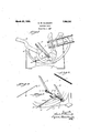
Fig. 1 is a broken'view in sids elevation 0f a printing press embodying 1ny invsntion;
Fig. 2 is a broken perspective view of a portion 01: the press9frame and the grippermechanism mounted thereon;
Fig. 3 is a detached perspective view 01 {ehe gripper-finger shaft; and
Fig. 4 is a corresponding view o-f the gripper-finger spring.
In carrying out my invention, as herein shown, I provide the gripper-finger sh-aft with a diaxnetrical socket 6 f01 the reception of the downWardlybent fii1ger 7 forrned at the forward end 011- a spring-arm 8, which, as W111 hereinafter appear, yieldingly 1nain tains 21 pir 01" gripperfingers 9 and 10 in spaced relationship to nhe oscillating p1aten 11 0f the press.
The gripper-fingers just mentioned am respectively monnted, by1neans 015 set-screws 12, flpon the opposite ends 0f the gripperfinge1 shaft 5 above referred-to, Which, in 1u1n, is journaled midwafy 01"; its 'Iength in a bearing-lug 13 formed upon a bifurcated platten-arm 14.
The platen 11 is pivotally monted upon 8, 1927. Sel'ia1 N0. 166,655.
by means 01 a link 19 t0 fhe upper rem= end 0f' the frame 15 aforesaid.
T0 provide a bea1ing in which the springarm 8 nmy reciprocate, the fra1ne 15 is f0rmed upon ting Ing 20having a longitudinal bezwingpassage 21 for the recePtion 01 the said arm.
A downward pr'essure upon he band-1eits side with a laterallyoflset- Ver 18 Will serve.ioswing the platen 11 toward the chase 16, so as to cause its forward face to engage the rear faces 0f the gripperwardly-bent fing'er 7 fr0m the socket 6 in the said shatft.
1. In a printing press, the combination wich the frame und oscillating platen thereof, of a transverselyarranged gripping-finger shaft carried by the Sa'id plateh, gripperfingers 1nounted upon said shaft, a transverse socket formed in said shaft, a reciprocating spring-arm providedat one ehd with anpffsetting coupling-finger adapted to enter the said socket and t0 be yieldingly held therein by the tension oi the spring-arm, and a bearing mounted upon the said frame for the reception and guidance 0f the said spnng-arm. v
2. In a printing press, the combination with the fmme anc1 oscillating platten there- 0f, 0f a transversely-mranged gripping-fin' ger shaft ca rried by the said platen, gripperfingers n1ounted upon said shaft, a dian1etrical socket formed 1n the said shaft, a remprocatmg spnngarm pr0v1ded at one end with an oflsetting coupling-finger adapted t o enter the said socket and to be yielclingly held therein by the tension 0f the spring arm, and a bearing-plug formed upon one side 0f' the said -frame for' the reception and guidance of the said spring-arm;
In testimony whereof, I have signed this specification.
. CHARLES W. GLASNAPR.
Priority Applications (1)
| Application Number | Priority Date | Filing Date | Title |
|---|---|---|---|
| US166655A US1663197A (en) | 1927-02-08 | 1927-02-08 | Printing press |
Applications Claiming Priority (1)
| Application Number | Priority Date | Filing Date | Title |
|---|---|---|---|
| US166655A US1663197A (en) | 1927-02-08 | 1927-02-08 | Printing press |
Publications (1)
| Publication Number | Publication Date |
|---|---|
| US1663197A true US1663197A (en) | 1928-03-20 |
Family
ID=22604181
Family Applications (1)
| Application Number | Title | Priority Date | Filing Date |
|---|---|---|---|
| US166655A Expired - Lifetime US1663197A (en) | 1927-02-08 | 1927-02-08 | Printing press |
Country Status (1)
| Country | Link |
|---|---|
| US (1) | US1663197A (en) |
Cited By (1)
| Publication number | Priority date | Publication date | Assignee | Title |
|---|---|---|---|---|
| US2593713A (en) * | 1945-07-12 | 1952-04-22 | Harry B Willett | Platen-bed press for simulating cylinder press printing |
-
1927
- 1927-02-08 US US166655A patent/US1663197A/en not_active Expired - Lifetime
Cited By (1)
| Publication number | Priority date | Publication date | Assignee | Title |
|---|---|---|---|---|
| US2593713A (en) * | 1945-07-12 | 1952-04-22 | Harry B Willett | Platen-bed press for simulating cylinder press printing |
Similar Documents
| Publication | Publication Date | Title |
|---|---|---|
| US1663197A (en) | Printing press | |
| US2162102A (en) | Hand stamp | |
| US1494184A (en) | Dating and numbering machine | |
| GB210087A (en) | Improved mechanism for feeding cardboard or paper webs in printing, stamping or embossing machines | |
| SU49973A1 (en) | Device for stamping numbers on a metal tape | |
| US1319716A (en) | A cobpobationi osi illistois | |
| US1543388A (en) | Sheet-positioning device for printing presses | |
| US1331924A (en) | Marking-machine | |
| US1457756A (en) | C spielman | |
| US305534A (en) | Theophilus eeichaed | |
| US1569461A (en) | Sheet-metal bending and forming machine | |
| US1547410A (en) | Self-inking hand stamp | |
| US215866A (en) | Improvement in canceling and dating stamps | |
| US539620A (en) | Henry johnson | |
| US230848A (en) | Charles | |
| SU22259A1 (en) | Press for cutting rubber shaped plates | |
| US975883A (en) | Brush for power marking-machines. | |
| US1440682A (en) | Paper-extracting mechanism for typewriting machines | |
| SU3351A1 (en) | A machine for making small metal articles, such as paper clips, etc. | |
| US1569363A (en) | Printing attachment for cap-forming machines | |
| SU8169A1 (en) | Device for automatically inserting sheets of blanket paper between printed sheets | |
| US887733A (en) | Automatic card-printing press. | |
| SU26230A1 (en) | The power switch to the carding machine when the thickness of the tail changes or if a foreign body enters | |
| US1259868A (en) | Hand-stamp. | |
| GB225675A (en) | Improvements relating to machines for punching stamping or inserting fasteners or the like in paper or like materials |