US1663186A - Fluid clutch and reverse gear - Google Patents
Fluid clutch and reverse gear Download PDFInfo
- Publication number
- US1663186A US1663186A US124073A US12407326A US1663186A US 1663186 A US1663186 A US 1663186A US 124073 A US124073 A US 124073A US 12407326 A US12407326 A US 12407326A US 1663186 A US1663186 A US 1663186A
- Authority
- US
- United States
- Prior art keywords
- shaft
- cylinders
- casing
- valve
- gear
- Prior art date
- Legal status (The legal status is an assumption and is not a legal conclusion. Google has not performed a legal analysis and makes no representation as to the accuracy of the status listed.)
- Expired - Lifetime
Links
Images
Classifications
-
- B—PERFORMING OPERATIONS; TRANSPORTING
- B60—VEHICLES IN GENERAL
- B60K—ARRANGEMENT OR MOUNTING OF PROPULSION UNITS OR OF TRANSMISSIONS IN VEHICLES; ARRANGEMENT OR MOUNTING OF PLURAL DIVERSE PRIME-MOVERS IN VEHICLES; AUXILIARY DRIVES FOR VEHICLES; INSTRUMENTATION OR DASHBOARDS FOR VEHICLES; ARRANGEMENTS IN CONNECTION WITH COOLING, AIR INTAKE, GAS EXHAUST OR FUEL SUPPLY OF PROPULSION UNITS IN VEHICLES
- B60K17/00—Arrangement or mounting of transmissions in vehicles
- B60K17/04—Arrangement or mounting of transmissions in vehicles characterised by arrangement, location, or kind of gearing
- B60K17/10—Arrangement or mounting of transmissions in vehicles characterised by arrangement, location, or kind of gearing of fluid gearing
Definitions
- This invention relates to a driving means for an automobile or other machine.
- the princi al objects of the invention are to provide a speed changing device and clutch without using the usual speed change gears; to provide a construction in which the power is transmitted through an oil clutch when the car or machine is running at high gear or at normal speed; and to provide in connection therewith a brake device which will reverse the transmission of the power.
- cruciform member comprising pistons and cylinders working in oil and operating eccentrically and to provide them with tapered passages for permitting the concentration of the pressure at the proper point and with ,a four-way valve to control the amount of fluid passing from cylinder to cylinder and havin ports of special shape to prevent too sud en closure.
- the invention also involves an operating means for reducing the speed in connection with the four pistons and cylinders and the valve, preferably comprising a flanged helical ring gear adapted to be moved on its own axis by the operating lever and co-operating with two helical pinions always in mesh therewith which will revolve and operate the above mentioned valve for controlling the speed of transmission.
- the invention also involves the provision of means whereby the said cylinders and pistons or cruciform construc tion is located in a casing filled with oil or other lubricant, and to provide sensitive valves which open automatically when the pressure is reduced inside the cylinders to admit oil thereto.
- This provides means whereby when the fluid in the cylinder un der pressure tends to reduce in volume through leakage passing by the piston rings, a vacuum is created in the cylinder and pressure is also set up in the casing outside the cylinders so that the oil will be pushed into the cylinders through said valves.
- I also provide means for transmitting the power from the construction above mentioned which is connected with the fly wheel to an eccentric bored convertor or shaft and from that to the driven shaft through a series of gears which maintain a stationary relation to each other during the normal driving.
- This combination reduces the loss by friction between the pistons and cylinders.
- the convertor serves three purposes; first, to revolve freely in the casing when idling; second, to act as a crank pin when the rotary fluid valves are closing gradually in the pistons at will and vice-versa; and third, as an idler gear support which is held stationary with a brake-band to give a reverse motion to the driven shaft, the rotary valves being open.
- This reversing mechanism operated by a brake-band is also a feature of this invention.
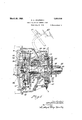
- FIG. 1 is a central sectional view throughout the entire device
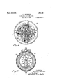
- Fi 2 is substantially a sectional view on the line 2-2 of Fig. 1;
- Fi 3 is a transverse sectional view on the line 33 of Fig. 1;
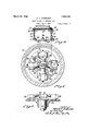
- Fig. 4 is an end view of the cruciform piston and cylinder construction showing the valve operating meansbut with the housing in section;
- Fig. 5 is a side view of two of the pistons showing the supporting means in central sectional view
- Fig. 6 is a skeleton plan, wlth parts omitted, showing the operation of the valve for the cruciform construction by means of the slidable spiral gear.
- This invention is capable of general use for transmitting power were different speeds are desired and also where it is desired to re verse the direction of drive, but I have shown it as applied to an automobile having a housing 10 which encloses the main part of the device.
- the motor shaft 11 is provided with a fly wheel 12 on which is bolted a casin 13 which, of course,'rotates constantly wit the motor shaft.
- This casing is provided with a hollow cylindrical end 14 which rests in a bearing 15 on the housing 10, being provided with a bushing for that purpose.
- the casing 13 and fly wheel 12 are secured together with suflicienttightness to prevent the leakage of oil and this casing is filled full of lubricating oil. These parts, of course, rotate on the axis of the motor shaft.
- the hollow projection 14 is provided with a bushing'in which rotates a shaft or convertor 16.
- This shaft is keyed to a housing 17 which is provided with two or more studs 18.
- gears 19 and 20 which are of different sizes and both mesh with an internal gear 21 riveted to a plate 22 which is fixed to the driven shaft 23 and is concentrid with it.
- This shaft is mounted in a bearing 24 provided with a stuifing box 25 which do not con stitute a part of this invention.
- a pinlon 27 which is fixed on a shaft 28 that has its bearing through the shaft 16 and is eccentrically mounted thereon. It will be seen therefore, that the three gears 19, 20 and 27 meshing on the outside with the internal ear 21, act as keys in the ordinary driving of the device to drive the driven shaft 23 at the same speed as the shaft 16 by the rotation of the shaft 28 therein, around the axis of the shaft 16 and the shaft 23.
- the shaft 28 is welded to a plate 30 inside the casing 13; On this plate there are two cylinders 31 opposite each other and doweled, or otherwise fixed, to the plate 30. They rotate with this plate 30 and are not movable with respect to it. Mounted on an axis at right angles to the axis of the two cylinders 31, are cylinders 32 which are like them but are doweled, or otherwise secured, to the casing 13 and thus they rotate positively with the fly wheel. It will be seen, therefore, thattthere are four cylinders rotatable about an axis and two of them shiftable radially together on account of the eccentricity of the bearing of the shaft 28.
- the cylinders are all in the same plane transverse to the axis of the various shafts mentioned and they are provided with two sets of pistons 33 and 34 connected together by a hub 35 and constituting a single unitary cruciform construction.
- These pistons are provided with packing or piston r1ngs36 for preventing lea age as much as possible. They are also provided with tapered passages .37 extending radially and gradually decreasing in size from the ends of the pistons to the center of the construction. At the center is located a circular valve 38 having cross ports 39 in communication with each other and as shown in Fig. 1 especially,
- a slidable spiral flanged gear 40 For the purpose of operating the valve 38, I use a slidable spiral flanged gear 40. This has a collar 41 and is shiftable along a key '42 carried by the end 14 of the casing 13.
- the foot pedal 43 in the present case is pivoted on a shaft 44 and provided with the usual s ring 45 for holding it up and with a roun ed projection 46 which operates a rod 47 to move it longitudinally.
- This rod is provided with a yoke 48 engaging the collar .tate about its axis.
- the shaft 44 has 'an arm 62 extending upwardly therefrom and an adjustable link 63 for operating a shaft 64 when the pedal 43 is depressed.
- This shaft is mounted on a bracket 65 and isprovided with means for appl ing a brake 67 to the surface of the housing 17 which is positively connected as stated with the shaft 16 and plate 24 which has the bearing for the driven shaft.
- the gear 40 which is in mesh with the pinions 50 slides and the power is transmitted never at rest as long as the fly wheel 12 is in motion, no matter whether idling or loaded.
- the shaft 28 is a driven shaft, rotated positively by the fly wheel at all times and at the same speed. The mechanical connection between these two parts absolutely insures this action.
- the shaft 28 rotates as a whole about the axis of the shaft 16 and therefore, the cylinders 31 shift radially as they ropass back and forth through the passages 37 and valve 38, which is in its open posi tion, of course, at this time and furnishes no resistance to this motion.
- the brake 67 is applied and the housing 17 and member 2% retarded or stopped. This causes the rotation of the gears 19 and 20 driven by the pinion 27 to reverse the direction of rotation of the shaft 23 through internal gear 21.
- a convertor shaft mounted concentrically with the driving shaft a shaft carried by the convertor shaft eccentrically and movably bodily around with the convertor shaft, a pair of cylinders fixed with respect to the last named shaft in alignment with each other, a pair of cylinders rotatable with said casing on axes at right angles oil secured to rotate therewith, of a convertor shaft mounted concentrically with the driving; shaft, a shaft carried by the convertor shaft eccentrically, a pair of cylinders fixed with respect to the last named shaft, a pair of cylinders rotatable with said casin on axes at right angles to the first name cylinders, a.
- cruciform member comprisin four pistons fixedly connected together an I working in the four cylinders and having longitudinal passages therethrough, and a valve carried by the cruciform member and having cross passages therethrough to permit the movement of oil freely when the valve is opened from a longitudinal passage in each piston to a longitudinal passage in the opposite piston, the valve being arranged to be turned to shut off the communication and change the speed of transmission.
- a shaft a pair of c linders in the casing fixed with respect to t e shaft and in alignment with each other, a. pair of cylinders rotatable with said casing on axes at right angles to the first named cylinders, a cruciform member comprising four pistons 'rigidly connected together and working with said four cylinders, a valve in the cruciform member adapted, when open, to permit the flow of liquid lubricant all the way through from the head of one cylinder to the head of the opposite cylinder, the pistons also having passages for that purpose, means for turning the valve to 'shut off the'fiow of lubricant, and automatic sensitive valves at the head of each cylinder for permitting the passage of lubricant into the cylinders when a vacuum is roduced therein.
- a valve in the cruciform construction adapted, when open, topermit the flow of one 0 linder to the head of the opposite cylin er, the pistons also having passages for that purpose, means for turning the valve to shut off the flow ofoil, and automatic sensitive valves at the head of each cylinder for permitting the passage of lubricant into the cylinders when a vacuum is produced therein.
- a fluid clutch the combination with a driving shaft, a casing secured to the driving shaft and adapted to be filled with a lubricating liquid, a shaft, means for supporting the lastnamed shaft eccentrically, and means for connecting the last named shaft with a driven shaft, of a cruciform construction in the casing having four pistons fixed with respect to each other and four cylinders arranged in two opposite pairs, one pair rotatable with the casing and the other pair rotatable with the eccentrically mounted shaft, a valve for controlling the flow of the lubricating oil between these cylinders, spiral pinions, a spiral gear in mesh withthe pinions, which when moved axially will turn said pinions on their own axes, means for operating the valve from said inions, and a pedal connected with the slidahle gear for operating it and controlling the clutch.
- a fluid clutch the combination with a driving shaft, a convertor shaft arranged in alignment, and a casing secured to the driving shaft and adapted to be filled with a lubricating liquid, of a shaft carried by the convertor shaft but eccentric with respect thereto rotatable on its own axis and rotatable bodily with the convertor shaft, means for connecting the last named shaft with a driven shaft for driving the latter, a cruciform construction having four pistons fixed with respect ..to each other and four cylinders arranged.
- a fluid clutch the combination with a driving shaft, a convertor shaft arranged in alignment therewith, a casing secured to the driving shaft and adapted to be filled with a lubricating liquid, a shaft carried by the convertor shaft but eccentric with respectthereto, rotatable on its own axis and rotatable bodily with the convertor'shaft, a set of gearing connectin the last named shaft with a driven sha t for driving the latter through said gearing, a cruciform construction having four pistons fixed with respect to each other and four cylinders arranged in two opposite pairs, one pair rotatable with the casing and one fixed to the eccentric shaft, means for controlling the flow of the lubricating liquid between these cylinders, comprising a valve, and means for pperating' the valve comprising spiral pinions and a spiral gear in mesh with the pinions, of a brake, comprising a brake member fixed with respect to the convertor shaft and rotatable with it, a stationary brake member adapted to be
- afluid clutch In afluid clutch, the combination with a drivin shaft, a casing secured to the driv-. ing sha t and adapted to be filled with a lubricating liquid, .a shaft eccentrically mounted, a cruciform construction having pistons fixed with respect to each other an relatively movable sets of cylinders, and means for controllin the flow of the lubri' eating oil between sald cylinders, of a brake, comprising a brake member fixed withrespect to the second-named shaft and rotatable with it, a stationary brake member adapted.
Description
A. C. ANDERSON 7 March 20, 1928. Y 1,663,186
FLUID CLUTCH AND REVERSE GEAR Filed July 21 1926 3 Sheets-Sheet 1 f 72 2/672 2507" Alfred (ZAnderuon. 5 1 flzzomgyd A. C. ANDERSON FLUID CLUTCH AND REVERSE GEAR March 20, 1928.
s Sheets-Sheet 2' Filed July 21 1926 [72 i/erzjzor' I Alfred C'Anderman March 20, 1928. 1,663,186
- A. vc. ANDERSON FLUID CLUTCH AND REVERSE GEAR Filed July 21 1926 5 Sheets-Sheet 5 In z/sntdr- Alfred GAnakmon.
Patented Mar. 20, 1928.
UNITED STATES AEFRED C. ANDERSON, 0F WORCESTER, MASSACHUSETTS.
FLUID CLUTCH A ND REVERSE GEAR.
Application filed July 21, 1926. Serial No. 124,073.
This invention relates to a driving means for an automobile or other machine. The princi al objects of the invention are to provide a speed changing device and clutch without using the usual speed change gears; to provide a construction in which the power is transmitted through an oil clutch when the car or machine is running at high gear or at normal speed; and to provide in connection therewith a brake device which will reverse the transmission of the power.
Other objects of the invention are to provide a cruciform member comprising pistons and cylinders working in oil and operating eccentrically and to provide them with tapered passages for permitting the concentration of the pressure at the proper point and with ,a four-way valve to control the amount of fluid passing from cylinder to cylinder and havin ports of special shape to prevent too sud en closure. The invention also involves an operating means for reducing the speed in connection with the four pistons and cylinders and the valve, preferably comprising a flanged helical ring gear adapted to be moved on its own axis by the operating lever and co-operating with two helical pinions always in mesh therewith which will revolve and operate the above mentioned valve for controlling the speed of transmission. The invention also involves the provision of means whereby the said cylinders and pistons or cruciform construc tion is located in a casing filled with oil or other lubricant, and to provide sensitive valves which open automatically when the pressure is reduced inside the cylinders to admit oil thereto. This provides means whereby when the fluid in the cylinder un der pressure tends to reduce in volume through leakage passing by the piston rings, a vacuum is created in the cylinder and pressure is also set up in the casing outside the cylinders so that the oil will be pushed into the cylinders through said valves. I also provide means for transmitting the power from the construction above mentioned which is connected with the fly wheel to an eccentric bored convertor or shaft and from that to the driven shaft through a series of gears which maintain a stationary relation to each other during the normal driving. This combination reduces the loss by friction between the pistons and cylinders. The convertor serves three purposes; first, to revolve freely in the casing when idling; second, to act as a crank pin when the rotary fluid valves are closing gradually in the pistons at will and vice-versa; and third, as an idler gear support which is held stationary with a brake-band to give a reverse motion to the driven shaft, the rotary valves being open. This reversing mechanism operated by a brake-band is also a feature of this invention.
Other objects and advantages of this invention will appear hereinafter.
Reference is to be had to the accompanying drawings in which Fig. 1 is a central sectional view throughout the entire device;
Fig. 4 is an end view of the cruciform piston and cylinder construction showing the valve operating meansbut with the housing in section;
Fig. 5 is a side view of two of the pistons showing the supporting means in central sectional view, and
Fig. 6 is a skeleton plan, wlth parts omitted, showing the operation of the valve for the cruciform construction by means of the slidable spiral gear.
This invention is capable of general use for transmitting power were different speeds are desired and also where it is desired to re verse the direction of drive, but I have shown it as applied to an automobile having a housing 10 which encloses the main part of the device. The motor shaft 11 is provided with a fly wheel 12 on which is bolted a casin 13 which, of course,'rotates constantly wit the motor shaft. This casing is provided with a hollow cylindrical end 14 which rests in a bearing 15 on the housing 10, being provided with a bushing for that purpose.
The casing 13 and fly wheel 12 are secured together with suflicienttightness to prevent the leakage of oil and this casing is filled full of lubricating oil. These parts, of course, rotate on the axis of the motor shaft. The hollow projection 14 is provided with a bushing'in which rotates a shaft or convertor 16. This shaft is keyed to a housing 17 which is provided with two or more studs 18. On these two studs are gears 19 and 20 which are of different sizes and both mesh with an internal gear 21 riveted to a plate 22 which is fixed to the driven shaft 23 and is concentrid with it. This shaft is mounted in a bearing 24 provided with a stuifing box 25 which do not con stitute a part of this invention.
Between the gears 19 and 20 is a pinlon 27 which is fixed on a shaft 28 that has its bearing through the shaft 16 and is eccentrically mounted thereon. It will be seen therefore, that the three gears 19, 20 and 27 meshing on the outside with the internal ear 21, act as keys in the ordinary driving of the device to drive the driven shaft 23 at the same speed as the shaft 16 by the rotation of the shaft 28 therein, around the axis of the shaft 16 and the shaft 23.
The shaft 28 is welded to a plate 30 inside the casing 13; On this plate there are two cylinders 31 opposite each other and doweled, or otherwise fixed, to the plate 30. They rotate with this plate 30 and are not movable with respect to it. Mounted on an axis at right angles to the axis of the two cylinders 31, are cylinders 32 which are like them but are doweled, or otherwise secured, to the casing 13 and thus they rotate positively with the fly wheel. It will be seen, therefore, thattthere are four cylinders rotatable about an axis and two of them shiftable radially together on account of the eccentricity of the bearing of the shaft 28.
The cylinders are all in the same plane transverse to the axis of the various shafts mentioned and they are provided with two sets of pistons 33 and 34 connected together by a hub 35 and constituting a single unitary cruciform construction. These pistons are provided with packing or piston r1ngs36 for preventing lea age as much as possible. They are also provided with tapered passages .37 extending radially and gradually decreasing in size from the ends of the pistons to the center of the construction. At the center is located a circular valve 38 having cross ports 39 in communication with each other and as shown in Fig. 1 especially,
and with the passages 37. These ports have a special shape, wide on one side and the sides concave and converging to a oint at the other. When these ports are in 1111 registration with the tapered passa es 37 there is no obstruction to the flow of t e oil. But when the valve turns away from that posit1on in a clockwise direction in Fig. 2 the flow of the oil, just before complete closing, 1s not cut off suddenly.
For the purpose of operating the valve 38, I use a slidable spiral flanged gear 40. This has a collar 41 and is shiftable along a key '42 carried by the end 14 of the casing 13.
The foot pedal 43 in the present case is pivoted on a shaft 44 and provided with the usual s ring 45 for holding it up and with a roun ed projection 46 which operates a rod 47 to move it longitudinally. This rod is provided with a yoke 48 engaging the collar .tate about its axis.
41 for shiftin the flanged gear 40. This spiral gear, w en shifted from the normal running position, will operate a pa1r of spiral pinions 50. Each one of these is fixed on a shaft 51 which extends through the balancingplate 30 and casing 13 which 15 provided with a pair of hollow tubes 54. The plate 30 is provided with .slots 52 for permitting the same. These shaft are connected with a pair of counterbalanced levers 55 which are connected by a link 56 in such relations that the two levers will always maintain a parallel relation with each other. They are both turned together so as to shift this link 56 longitudinally. This link is provided with a slot 57 to permit of this motion and in this slot is a slide 58 which is caused to move with the link. This slide is provided with a pin connected with a crank disc 59 on the Valve 38. for turning this valve on its own axis. Thus the valve is controlled and operated.
It will be noticed that the shaft 44 has 'an arm 62 extending upwardly therefrom and an adjustable link 63 for operating a shaft 64 when the pedal 43 is depressed. This shaft is mounted on a bracket 65 and isprovided with means for appl ing a brake 67 to the surface of the housing 17 which is positively connected as stated with the shaft 16 and plate 24 which has the bearing for the driven shaft.
In the operation of the device, when the foot pedal is in neutral -or pushed down, the gear 40, which is in mesh with the pinions 50 slides and the power is transmitted never at rest as long as the fly wheel 12 is in motion, no matter whether idling or loaded. The shaft 28 is a driven shaft, rotated positively by the fly wheel at all times and at the same speed. The mechanical connection between these two parts absolutely insures this action. The shaft 28 rotates as a whole about the axis of the shaft 16 and therefore, the cylinders 31 shift radially as they ropass back and forth through the passages 37 and valve 38, which is in its open posi tion, of course, at this time and furnishes no resistance to this motion. The rotation of the shaft 28 about the axis of the shaft This causes the oil to numbers of teeth and both meshing with the internal gear 21, causes this gear to rotate exactly with the (pinion 27. As the gears 19 and 20 are fixe to the housing 17 and as the gear 21 is fixed to the plate 22, these parts rotate positively with the shaft 28 and the driven shaft 23 is driven at the desired speed.
Now if the foot pedal 43 is allowed to rise by the aid of the spring45, the gear 40, still in mesh with the pinions 50, is moved and these, through the instrumentalities above described and shown particularly in Figs. 4 and 5, rotate the valve 38 on its own axis. The instant that it is turned so that the ports do not register exactly with the passages 37, resistance will be set up to the passage of the oil through them and the rotation of the shaft 16 will gradually increase in speed and this will be transmitted exactly to the driven shaft 23. The more the pedal is allowed to rise the more the spiral gear 40 turns the spiral pinions 50, and the greater will be the resistance. When this valve is turned so far that its ports are entirely out of mesh with the passages 37, the power will be positively transmitted to the shaft 23. The sensitive valves 70 are held closed by their springs and they open automatically when forced by the pressure outside the cylinders.
If it is desired to reverse, the brake 67 is applied and the housing 17 and member 2% retarded or stopped. This causes the rotation of the gears 19 and 20 driven by the pinion 27 to reverse the direction of rotation of the shaft 23 through internal gear 21.
Although I have illustrated and describedonly a sin le form of the invention, I am aware of t e fact that modifications can be made therein by any person skilled in the art without departing from the scope of'the invention as expressed in the claims. Therefore, I do not wish to be limited to all the details of construction herein shown and described, but what I do claim is 1. In a fluid clutch and speed change gearing, the combination with a driving shaft and a casing for a liquid secured to rotate therewith, of a shaft, cylinders fixed with respect to the last named shaft, cylinders rotatable with said casing, and istons'connected together and working in t e cylinders and constituting means for transmitting the motion of rotation to the last named shaft from the first named cylinders.
2. In a fluid clutch and speed change gearing, the combination with a driving shaft and a casing for a liquid secured to rotate therewith, of a convertor shaft mounted concentrically with the driving shaft, a shaft carried by the convertor shaft eccentrically and movably bodily around with the convertor shaft, a pair of cylinders fixed with respect to the last named shaft in alignment with each other, a pair of cylinders rotatable with said casing on axes at right angles oil secured to rotate therewith, of a convertor shaft mounted concentrically with the driving; shaft, a shaft carried by the convertor shaft eccentrically, a pair of cylinders fixed with respect to the last named shaft, a pair of cylinders rotatable with said casin on axes at right angles to the first name cylinders, a. cruciform member comprisin four pistons fixedly connected together an I working in the four cylinders and having longitudinal passages therethrough, and a valve carried by the cruciform member and having cross passages therethrough to permit the movement of oil freely when the valve is opened from a longitudinal passage in each piston to a longitudinal passage in the opposite piston, the valve being arranged to be turned to shut off the communication and change the speed of transmission.
4. In a fluid clutch, the combination with a driving shaft and a casing having a lubricant therein and secured to rotate therewith,
'of a shaft, a pair of c linders in the casing fixed with respect to t e shaft and in alignment with each other, a. pair of cylinders rotatable with said casing on axes at right angles to the first named cylinders, a cruciform member comprising four pistons 'rigidly connected together and working with said four cylinders, a valve in the cruciform member adapted, when open, to permit the flow of liquid lubricant all the way through from the head of one cylinder to the head of the opposite cylinder, the pistons also having passages for that purpose, means for turning the valve to 'shut off the'fiow of lubricant, and automatic sensitive valves at the head of each cylinder for permitting the passage of lubricant into the cylinders when a vacuum is roduced therein.
5. In a uid clutch, the combination with a. driving shaft and a casing for lubricant secured to rotate therewith, of a convertor shaft mounted concentrically with the driving shaft, a shaft carried-by the convertor shaft eccentrically and movable bodily, around with the convertorshaft, a. cruciform construction comprising four pistons and cylinders in the casing, the pistons all being rigidly connected together and the cylinders being in two pairs, one pair movable transversely to the axis of the other pair and rotatable with the. casing and the other pair rotatable with the eccentric shaft, a valve in the cruciform construction adapted, when open, topermit the flow of one 0 linder to the head of the opposite cylin er, the pistons also having passages for that purpose, means for turning the valve to shut off the flow ofoil, and automatic sensitive valves at the head of each cylinder for permitting the passage of lubricant into the cylinders when a vacuum is produced therein.
6. In a fluid clutch, the combination with a driving shaft, a casing secured to the driving shaft and adapted to be filled with a lubricating liquid, a shaft, means for supporting the lastnamed shaft eccentrically, and means for connecting the last named shaft with a driven shaft, of a cruciform construction in the casing having four pistons fixed with respect to each other and four cylinders arranged in two opposite pairs, one pair rotatable with the casing and the other pair rotatable with the eccentrically mounted shaft, a valve for controlling the flow of the lubricating oil between these cylinders, spiral pinions, a spiral gear in mesh withthe pinions, which when moved axially will turn said pinions on their own axes, means for operating the valve from said inions, and a pedal connected with the slidahle gear for operating it and controlling the clutch. L
7. In a fluid clutch, the combination with a driving shaft, a convertor shaft arranged in alignment, and a casing secured to the driving shaft and adapted to be filled with a lubricating liquid, of a shaft carried by the convertor shaft but eccentric with respect thereto rotatable on its own axis and rotatable bodily with the convertor shaft, means for connecting the last named shaft with a driven shaft for driving the latter, a cruciform construction having four pistons fixed with respect ..to each other and four cylinders arranged. in 'two.opposite pairs in the casing, one pair rotatable with the casing and one fixed to the eccentric shaft, a valve for controlling the flow of the lubricating liquid between these cylinders, spiral pinions connected with the valve for operating it, a s iral gear in mesh with the pinions, a: slidab e link, means for guiding the link to slide, means on the pinions 7 for sliding said link back and forth, and
means connected with the link for turning the valve as the link slides.
8. In a fluid clutch, the combination with a driving shaft, a convertor shaft arranged in alignment therewith, a casing secured to the driving shaft and adapted to be filled with a lubricating liquid, a shaft carried by the convertor shaft but eccentric with respectthereto, rotatable on its own axis and rotatable bodily with the convertor'shaft, a set of gearing connectin the last named shaft with a driven sha t for driving the latter through said gearing, a cruciform construction having four pistons fixed with respect to each other and four cylinders arranged in two opposite pairs, one pair rotatable with the casing and one fixed to the eccentric shaft, means for controlling the flow of the lubricating liquid between these cylinders, comprising a valve, and means for pperating' the valve comprising spiral pinions and a spiral gear in mesh with the pinions, of a brake, comprising a brake member fixed with respect to the convertor shaft and rotatable with it, a stationary brake member adapted to be brought into contact with the first-named brake member for slowing it up, 9. In afluid clutch, the combination with a drivin shaft, a casing secured to the driv-. ing sha t and adapted to be filled with a lubricating liquid, .a shaft eccentrically mounted, a cruciform construction having pistons fixed with respect to each other an relatively movable sets of cylinders, and means for controllin the flow of the lubri' eating oil between sald cylinders, of a brake, comprising a brake member fixed withrespect to the second-named shaft and rotatable with it, a stationary brake member adapted. to be brought into contact with the first-named brake member for slowing it up, and gearing between the shaft carried by the second-named shaft and the driven shaft shaft and rotatable with it, a stationary brake member adapted to be brought into contact with the first-named brake member .for slowing it down and thus slowing down the second shaft, a driven shaft and reversing gearing between the second-named shaft and the drlven shaft.
In'testimony whereof I have hereunto affixed my signature.
ALFRED G, ANDERSON.
Priority Applications (1)
| Application Number | Priority Date | Filing Date | Title |
|---|---|---|---|
| US124073A US1663186A (en) | 1926-07-21 | 1926-07-21 | Fluid clutch and reverse gear |
Applications Claiming Priority (1)
| Application Number | Priority Date | Filing Date | Title |
|---|---|---|---|
| US124073A US1663186A (en) | 1926-07-21 | 1926-07-21 | Fluid clutch and reverse gear |
Publications (1)
| Publication Number | Publication Date |
|---|---|
| US1663186A true US1663186A (en) | 1928-03-20 |
Family
ID=22412584
Family Applications (1)
| Application Number | Title | Priority Date | Filing Date |
|---|---|---|---|
| US124073A Expired - Lifetime US1663186A (en) | 1926-07-21 | 1926-07-21 | Fluid clutch and reverse gear |
Country Status (1)
| Country | Link |
|---|---|
| US (1) | US1663186A (en) |
Cited By (1)
| Publication number | Priority date | Publication date | Assignee | Title |
|---|---|---|---|---|
| US20140196675A1 (en) * | 2010-11-10 | 2014-07-17 | Gary Ray Robert Waissi | Crankdisk bearing support for the waissi internal combustion engine |
-
1926
- 1926-07-21 US US124073A patent/US1663186A/en not_active Expired - Lifetime
Cited By (2)
| Publication number | Priority date | Publication date | Assignee | Title |
|---|---|---|---|---|
| US20140196675A1 (en) * | 2010-11-10 | 2014-07-17 | Gary Ray Robert Waissi | Crankdisk bearing support for the waissi internal combustion engine |
| US8875673B2 (en) * | 2010-11-10 | 2014-11-04 | Gary Ray Robert Waissi | Crankdisk bearing support for the waissi internal combustion engine |
Similar Documents
| Publication | Publication Date | Title |
|---|---|---|
| US2019146A (en) | Transmission mechanism | |
| US2645903A (en) | Variable ratio rotary pump and motor hydraulic transmission | |
| US1840872A (en) | Power transmission | |
| US2380734A (en) | Hydraulic transmission | |
| US2066450A (en) | Hydraulic clutch | |
| US2467226A (en) | Variable-speed and torque drive | |
| US1663186A (en) | Fluid clutch and reverse gear | |
| US2015626A (en) | Hydraulic transmission apparatus | |
| US1364325A (en) | Power-transmission mechanism | |
| US2484015A (en) | Positive displacement hydraulic transmission | |
| US2242112A (en) | Hydraulic transmission | |
| US2923177A (en) | Speed reducer, over-drive and braking unit | |
| US2219052A (en) | Transmission | |
| US1646020A (en) | Differential gear for motor vehicles | |
| US2230545A (en) | Hydraulic rotary variable transmission mechanism | |
| US1715778A (en) | Variable-speed transmission | |
| US2140886A (en) | Hydraulic clutch | |
| US2170930A (en) | Transmission apparatus | |
| US2434590A (en) | Hydraulic transmission | |
| US1456956A (en) | Fluid-controlled transmission | |
| US2126662A (en) | Hydraulic transmission | |
| US1930059A (en) | Hydraulic power transmission mechanism | |
| US1368476A (en) | Transmission-gearing | |
| US2488408A (en) | Hydraulic variable-speed motion transmission | |
| US1363907A (en) | Fluid transmission |